Table of Contents
Advertisement
Quick Links
Advertisement
Table of Contents

Related Manuals for Cervis MCB Series

Summary of Contents for Cervis MCB Series
- Page 1 ™ Mini Console Box Remote MCB User Manual U092.1.1 2019 Cervis, Inc.
- Page 2 SmaRT MCB This document is the property of Cervis, Inc. and cannot be copied, modified, e-mailed, or reproduced without the express prior written consent of Cervis, Inc. Cervis, Inc. reserves the right to change this manual or edit, delete, or modify any information without prior notification.
-
Page 3: Table Of Contents
Table of Contents .......................... i List of Figures ..........................i List of Tables ..........................i Cervis, Inc. Safety Precautions ....................iii 1.0 Introduction .......................... 1 2.0 Mini Console Box Layout ....................4 2.1 Standard Joysticks, Toggle Switches, and Pushbuttons ..........4 2.2 LEDs ........................... - Page 4 SmaRT MCB Table 4. MCB Model Specific Features ..................18 Table 5. MCB Specifications ....................... 19 U092.1.1...
-
Page 5: Cervis, Inc. Safety Precautions
User Manual Cervis, Inc. Safety Precautions Read and follow all instructions. Failure to abide by Safety Precautions may result in equipment failure, loss of authority to operate the equipment, and personal injury. Use and maintain proper wiring. Follow equipment manufacturer instructions. -
Page 7: Introduction
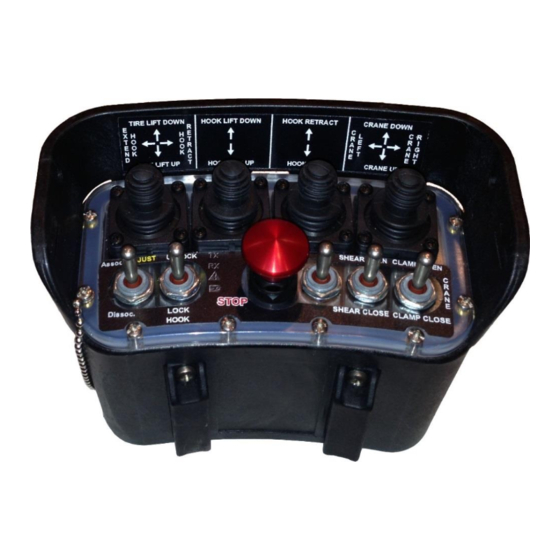
Pulse Width Modulation (PWM) joystick/potentiometer calibrations. The standard MCB switch and joystick options include those illustrated with the example in Figure 1. Note: Documents included with the SmaRT system when it is sent to you include an MCB’s specific operational details. 2019 Cervis, Inc. -
Page 8: Figure 1. Mcb-Xh04Js Mini Console Box Example
SmaRT MCB Magnet Battery Compartment (cover removed) Power Button Magnet Figure 1. MCB-xH04JS Mini Console Box Example U092.1.1... - Page 9 The MCB can have up to five (5) toggle switches with the possibility of six toggle switches at the expense of a joystick position. As previously mentioned, Cervis, Inc. also offers the choice of a CAN communication connector for use with an umbilical cable for backup control.
-
Page 10: Mini Console Box Layout
SmaRT MCB 2.0 Mini Console Box Layout 2.1 Standard Joysticks, Toggle Switches, and Pushbuttons Table 1 lists the standard MCB switches. Table 1. Mini Console Box Switches Switch Function Type Switch Type/Description J1 through J4 Factory Programmable Variable Joystick Single or Dual Axis S1 through S5 Factory Programmable Toggle... - Page 11 M-Stop engaged Keyswitch moved to OFF Select Unit wake-up without switch S12 Shutting Off: Batteries below operating level; unit shutting down; replace batteries with fresh set. Select Shutting Off: Joystick/Lever command reached out-of-bounds. Condition unsafe, operation turning off. 2019 Cervis, Inc.
-
Page 12: Optional Mini Console Box Umbilical Connection
SmaRT MCB 2.3 Optional Mini Console Box Umbilical Connection A CAN communications umbilical connection is an available option that can be used for backup control of base unit(s). The MCB radio frequency (RF) shuts off when an umbilical is connected to the MCB. -
Page 13: Attaching The Harness To The Mcb
Connect the two parts of the rip cord together, and press down to secure the connection. 2.4.2 Attaching the Harness to the MCB Both ends of the high-visibility orange straps feature a pair of heavy-duty metal button snaps at the ends. 2019 Cervis, Inc. - Page 14 SmaRT MCB To attach the harness to your MCB-9XL, locate the two T-shaped harness clips on the front of your MCB. Thread the high visibility orange straps through the harness mounts—snap side up—past the first two (female) snaps. U092.1.1...
- Page 15 User Manual Fold the strap over onto itself, and fasten the female snaps to their male counterparts. Note: You’ll know the snaps are secured when you hear a clicking sound. 2019 Cervis, Inc.
- Page 16 SmaRT MCB When you have the harness securely together, hang it around your neck—or drape it over your shoulder—and begin operating your MCB. U092.1.1...
-
Page 17: Mini Control Box Battery
At this time, the Battery LED begins to blink once per second until the voltage reaches the Auto- Shutdown voltage. Cervis, Inc. recommends replacing the batteries as soon as possible once the Battery LED begins flashing. Replacement batteries must be four new AA cell batteries, all made by the same manufacturer. -
Page 18: Mcb On/Off
STOP (Standard, but the pushbutton can be custom configured by request at Cervis) Figure 4. Turn MCB On and Off Cervis, Inc. Engineering can custom configure the MCB inactivity timer. Four minutes is the standard setting for an MCB. U092.1.1... -
Page 19: Mcb Associate Mode
“Associate” Mode establishes the communications link between the MCB remote and base unit. (SmaRT systems are Associated before leaving Cervis, Inc.) To associate, have a clear line of sight between the MCB and the base, and both units must be OFF (powered down). - Page 20 SmaRT MCB 5. Power-up the base unit. 6. When all LEDs illuminate, release switch S1 and the green pushbutton. Association is successful when the TX and RX LEDs blink rapidly while the Battery and Error LEDs are unlit. U092.1.1...
-
Page 21: Mcb Joystick Adjustments
Push and hold for approximately Push and hold S1 five seconds until LEDs flash Figure 6. Enter Adjust Mode Be aware of joystick activation during this process. Base Unit Caution! outputs may be active or activated during the adjustment process. 2019 Cervis, Inc. -
Page 22: Low End Calibration (Min)
SmaRT MCB 6.2 Low End Calibration (Min) LED 8 on the base unit lights solid, indicating that it is in Minimum Adjust Mode. 1. To set the minimum activation of the joystick to be adjusted, activate the desired joystick beyond 50% deflection and release it back to its neutral position. LED 8 on the base unit flashes, indicating minimum adjustment. - Page 23 User Manual Pressing the green pushbutton for about 3–4 seconds. 2019 Cervis, Inc.
-
Page 24: Mcb Product Family Listing
900MHz 10mW 4-Dual Axis MCB-2H02JS 2.4GHz 100mW 2-Dual Axis MCB-2H02JS-UMB 2.4GHz 100mW 2-Dual Axis MCB-2H04JS 2.4GHz 100mW 4-Dual Axis MCB-2H04JS-UMB 2.4GHz 100mW 4-Dual Axis Custom Configurations by Request Call Cervis, Inc. at (724) 741-9000 and ask for Inside Sales. U092.1.1... -
Page 25: Mini Console Box Specifications
Solid Indicates error with handheld remote BATT Low battery indication Control Toggles Two- or three-position momentary or maintained Switches Joysticks Four single or dual axis M-Stop Professional Machine Stop Power Green pushbutton Umbilical See Section 2.3 Connector 2019 Cervis, Inc. -
Page 26: Appendix A: Exposure To Radio Frequency Energy
SmaRT MCB Appendix A: Exposure to Radio Frequency Energy SmaRT mini console box remote units contain radio transceivers. When active, an MCB remote sends out radio frequency (RF) energy through its internal antenna. The SmaRT handheld remote complies with limits set by the United States Federal Communications Commission (FCC) for operating distance from human tissue. -
Page 27: Appendix C: Declaration Of Conformity For Mcb-2H0Xjs
User Manual Appendix C: Declaration of Conformity for MCB-2H0xJS Figure 8. Declaration of Conformity for MCB-2H0xJS 2019 Cervis, Inc. - Page 28 SmaRT MCB www.cervisinc.com Visit our Web site at: 2019 Cervis, Inc. All rights reserved. Content is subject to change without notice. U092.1.1...
Need help?
Do you have a question about the MCB Series and is the answer not in the manual?
Questions and answers