Table of Contents
Advertisement
Quick Links
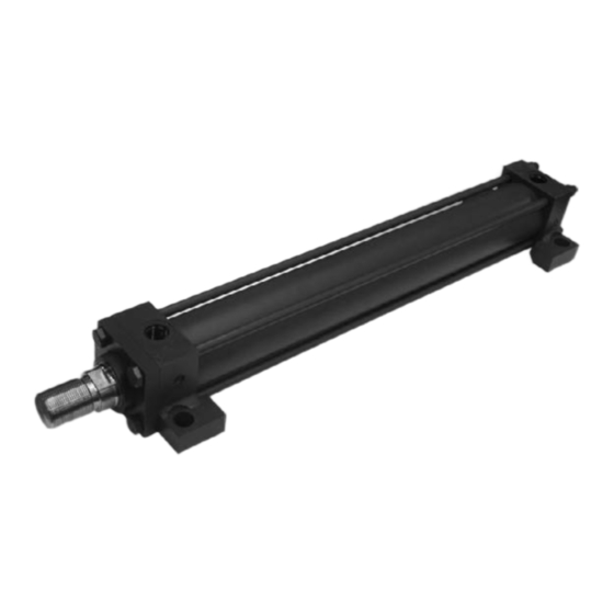
Hydraulic Cylinder
NFPA Industrial Type
Model CDT1/CGT1
Series 1X
Nominal pressure: Up to 1,500 psi maximum
Table of contents
Contents
Features
Page
- Duty, up to 1,500 psi (see chart on page 2)
- Standards, meets or exceeds all JIC and NFPA requirements
2
- Bore Sizes, 1-1/2" - 8"
2
- Piston Rods, 1/2" - 5-1/2"
3
- Mountings,18 standard NFPA mountings
3
- Ports, SAE o-ring straight thread ports
4
- Stroke, standard strokes furnished in 1/8" increments. Normal
6
stroke tolerance + 1/16" / -0". Closer stroke tolerances avail-
7
able; consult factory.
8
- Rod End Threads, standard KK1 male and female threads plus
26
KK2 oversize male thread. Other rod end styles optional.
28
- Cushions, available for all bore sizes, at either or both ends.
33
37
44
Project planning software
Interactive Catalog System
Online
RA 17038/02.13
Replaces: 11.12
www.boschrexroth.com/ics
1/44
Advertisement
Table of Contents

Summary of Contents for Bosch Rexroth CDT1 Series
-
Page 1: Table Of Contents
Hydraulic Cylinder RA 17038/02.13 1/44 Replaces: 11.12 NFPA Industrial Type Model CDT1/CGT1 Series 1X Nominal pressure: Up to 1,500 psi maximum Features Table of contents Contents Page – Duty, up to 1,500 psi (see chart on page 2) – Standards, meets or exceeds all JIC and NFPA requirements Technical Data –... -
Page 2: Technical Data
MF1 and MF2 have maximum operating pressures Acceptance: of 1,000 psi for 1-1/2" through 4" bore sizes Each cylinder is tested to Bosch Rexroth standards. b) A 2.5" bore with a 5/8" rod has a maximum pressure Cylinders, outside the above parameters are also available. -
Page 3: Area, Forces, Flow
RA 17038/02.13 | CDT1/CGT1 Industrial Hydraulics | Bosch Rexroth Corp. 3/44 Areas, Forces, Flows (dimensions in inches) Piston Area Areas Force at 500 psi Flow at 4”/s Bore ratio Piston Annulus Push Regen. Pull Regen. Ø in. Ø in. 1.500 0.625... -
Page 4: Ordering Details
4/44 Bosch Rexroth Corp. | Industrial Hydraulics CDT1/CGT1 | RA 17038/02.13 Ordering Details Z 1X Single rod cylinder = CD Double rod cylinder = CG Further details in clear text Option 2 Series = T1 Without options Thrust key Stop tube (specify length) - Page 5 RA 17038/02.13 | CDT1/CGT1 Industrial Hydraulics | Bosch Rexroth Corp. 5/44 Sealing System "M" Polyurethane seal system (standard) 1. Double lip wiper 3. Double acting piston seal 2. U-cup rod seal 4. Wear bands 5. Piston threaded and sealed to piston rod with permanent adhesive and mechanically secured with a set screw.
-
Page 6: Piston Rod Versions
6/44 Bosch Rexroth Corp. | Industrial Hydraulics CDT1/CGT1 | RA 17038/02.13 Piston Rod Versions Male Rod End S.A.F.E. Rod End Option H & D Option T D (width across flats) Female Rod End Option E Rod Thread Options: Standard KK1 Male furnished when not specified. -
Page 7: Mounting Type Overview
RA 17038/02.13 | CDT1/CGT1 Industrial Hydraulics | Bosch Rexroth Corp. 7/44 Mounting Type Overview MF5 (see Page 8, 9) MF1 (see Page 8, 9) MF2 (see Page 8, 9) MF6 (see Page 8, 9) MP1 (see Page 10, 11) MP3 (see Page 10, 11) -
Page 8: Dimensional Data
8/44 Bosch Rexroth Corp. | Industrial Hydraulics CDT1/CGT1 | RA 17038/02.13 Mounting MF1, MF2, MF5, MF6 CDT1 MF1 ZB + STROKE ZJ + STROKE P + STROKE FB (NOMINAL BOLT DIAMETER) LB + STROKE CDT1 MF2 ZF + STROKE ZJ + STROKE... - Page 9 RA 17038/02.13 | CDT1/CGT1 Industrial Hydraulics | Bosch Rexroth Corp. 9/44 Dimensions MF1, MF2, MF5, MF6 Table 1 - Dimensions affected by rod diameter Bore 1.500 0.625 0.25 0.63 1.94 4.88 5.00 4.63 Flange mounts are one of the stron- 1.000...
- Page 10 10/44 Bosch Rexroth Corp. | Industrial Hydraulics CDT1/CGT1 | RA 17038/02.13 Mounting MP1, MP3 CDT1 MP1 ZC + STROKE ZJ + STROKE P + STROKE E SQUARE Ø CD LB + STROKE XC + STROKE CDT1 MP3 ZC + STROKE...
- Page 11 RA 17038/02.13 | CDT1/CGT1 Industrial Hydraulics | Bosch Rexroth Corp. 11/44 Dimensions MP1, MP3 Table 1 - Dimensions affected by rod diameter Bore Ø Rod Ø 1.500 0.625 0.25 0.63 1.94 5.38 5.88 4.63 1.000 0.50 1.00 2.31 5.75 6.25 5.00...
- Page 12 12/44 Bosch Rexroth Corp. | Industrial Hydraulics CDT1/CGT1 | RA 17038/02.13 Mounting MP5 CDT1 MP5 ZH + STROKE ZJ + STROKE P + STROKE E SQUARE +.0000 -.0006 Ø CD +.000 -.005 LB + STROKE XH + STROKE...
- Page 13 RA 17038/02.13 | CDT1/CGT1 Industrial Hydraulics | Bosch Rexroth Corp. 13/44 Dimensions MP5 Table 1 - Dimensions affected by rod diameter Bore The MP5 (Universal) type mount is a pivot mount 1.500 0.625 0.25 0.63 1.94 5.50 6.13 4.63 with a spherical bearing fitted into the pivot 1.000...
- Page 14 14/44 Bosch Rexroth Corp. | Industrial Hydraulics CDT1/CGT1 | RA 17038/02.13 Mounting MS2, MS4 CDT1 MS2 ZB + STROKE ZJ + STROKE P + STROKE E SQUARE -.003 -.008 Ø LB + STROKE 4 HOLES SS + STROKE CDT1 MS4...
- Page 15 RA 17038/02.13 | CDT1/CGT1 Industrial Hydraulics | Bosch Rexroth Corp. 15/44 Dimensions MS2, MS4 Table 1 - Dimensions affected by rod diameter Bore 1.500 0.625 0.25 0.63 1.94 1.38 1.94 4.88 4.63 1.000 0.50 1.00 2.31 1.75 2.31 5.25 5.00 2.000...
- Page 16 16/44 Bosch Rexroth Corp. | Industrial Hydraulics CDT1/CGT1 | RA 17038/02.13 Mounting MS3, MS7 CDT1 MS3 ZB + STROKE ZJ + STROKE P + STROKE Ø 4 HOLES SS + STROKE LB + STROKE CDT1 MS7 ZE + STROKE XE + STROKE...
- Page 17 RA 17038/02.13 | CDT1/CGT1 Industrial Hydraulics | Bosch Rexroth Corp. 17/44 Dimensions MS3, MS7 Table 1 - Dimensions affected by rod diameter Bore 1.500 0.625 0.25 0.63 1.94 5.38 1.38 4.88 4.63 5.63 1.000 0.50 1.00 2.31 5.75 1.75 5.25 5.00...
- Page 18 18/44 Bosch Rexroth Corp. | Industrial Hydraulics CDT1/CGT1 | RA 17038/02.13 Mounting MT1, MT2 CDT1 MT1 ZJ + STROKE P + STROKE E SQUARE +.000 -.001 Ø TD LB + STROKE CDT1 MT2 ZJ + STROKE P + STROKE E SQUARE +.000...
- Page 19 RA 17038/02.13 | CDT1/CGT1 Industrial Hydraulics | Bosch Rexroth Corp. 19/44 Dimensions MT1, MT2 Table 1 - Dimensions affected by rod diameter Bore 1.500 0.625 0.25 0.63 1.94 1.75 4.13 4.63 All trunnion mount cylinders need a provision 1.000 0.50 1.00...
- Page 20 20/44 Bosch Rexroth Corp. | Industrial Hydraulics CDT1/CGT1 | RA 17038/02.13 Mounting MT4 CDT1 MT4 ZJ + STROKE P + STROKE +.000 -.001 LB + STROKE All trunnion mounted cylinders need a provision on both ends for pivoting. These types of cylinders are designed to carry...
- Page 21 RA 17038/02.13 | CDT1/CGT1 Industrial Hydraulics | Bosch Rexroth Corp. 21/44 Dimensions MT4 Table 1 - Dimensions affected by rod diameter Bore Min. 1.500 0.625 0.25 0.63 1.94 3.19 4.63 1.000 0.50 1.00 2.31 3.56 5.00 2.000 0.625 0.25 0.63 1.94...
- Page 22 22/44 Bosch Rexroth Corp. | Industrial Hydraulics CDT1/CGT1 | RA 17038/02.13 Mounting MX0 CDT1 MX0 ZJ + STROKE P + STROKE E SQUARE LB + STROKE...
- Page 23 RA 17038/02.13 | CDT1/CGT1 Industrial Hydraulics | Bosch Rexroth Corp. 23/44 Dimensions MX0 Table 1 - Dimensions affected by rod diameter Bore Ø Rod Ø 1.500 0.625 0.25 0.63 1.94 4.63 Rod end options shown on page 6. 1.000 0.50 1.00...
- Page 24 24/44 Bosch Rexroth Corp. | Industrial Hydraulics CDT1/CGT1 | RA 17038/02.13 Mounting MX1, MX2, MX3 CDT1 MX1 ZT + STROKE ZJ + STROKE P + STROKE E SQUARE ØAA DD THD. +.000 -.003 Ø B LB + STROKE CDT1 MX2...
- Page 25 RA 17038/02.13 | CDT1/CGT1 Industrial Hydraulics | Bosch Rexroth Corp. 25/44 Dimensions MX1, MX2, MX3 Table 1 - Dimensions affected by rod diameter Bore 1.500 0.625 0.25 0.63 1.94 4.63 5.62 Tie Rod and Flange Mounts are basically the 1.000 0.50...
-
Page 26: Double Rod Cylinders
26/44 Bosch Rexroth Corp. | Industrial Hydraulics CDT1/CGT1 | RA 17038/02.13 Mounting CGT1 CGT1 ZM + 2X STROKE P + STROKE Y + STROKE E SQUARE EE (NPTF) W + STROKE LD + STROKE Pressure Ratings for Double Rod End... - Page 27 RA 17038/02.13 | CDT1/CGT1 Industrial Hydraulics | Bosch Rexroth Corp. 27/44 Mounting CGT1 Table 1 - Dimensions affected by rod diameter Bore 1.500 0.625 0.25 0.63 1.94 5.73 6.13 1.000 0.50 1.00 2.31 6.10 6.88 2.000 0.625 0.25 0.63 1.94 5.78...
-
Page 28: Mounting Accessories
28/44 Bosch Rexroth Corp. | Industrial Hydraulics CDT1/CGT1 | RA 17038/02.13 Rexroth Cylinder Accessories Rod Clevises Part No. R978935057 .765 0.50 1.50 1.00 0.50 1.00 0.75 0.75 7/16-20 0.50 R978935058 1.265 0.75 2.38 1.25 0.63 1.25 1.25 1.13 3/4-16 0.75 R978935059 1.265... - Page 29 RA 17038/02.13 | CDT1/CGT1 Industrial Hydraulics | Bosch Rexroth Corp. 29/44 Rexroth Cylinder Accessories Spherical Rod Eyes Part No. CD -.0005 R978935075 0.500 1.06 0.88 0.44 0.88 0.75 7/16-20 0.88 R978935076 0.750 1.00 1.25 2.03 1.25 1.06 3/4-16 1.31 R978935077 1.000...
- Page 30 30/44 Bosch Rexroth Corp. | Industrial Hydraulics CDT1/CGT1 | RA 17038/02.13 Rexroth Cylinder Accessories Eye Brackets Part No. R978935036 0.75 0.50 13/32 2.50 0.38 1.13 0.75 0.50 0.56 1.63 R978935037 1.25 0.75 17/32 3.50 0.63 1.88 1.25 0.75 0.88 2.56 R978935038 1.50...
- Page 31 RA 17038/02.13 | CDT1/CGT1 Industrial Hydraulics | Bosch Rexroth Corp. 31/44 Rexroth Cylinder Accessories Pivot Pins-Grooved Pivot Pins C-Rings Part No. Part No. R978935026 0.500 0.468 2.094 1.875 0.041 0.109 R978000049 0.500 R978935027 0.750 0.704 2.875 2.625 0.048 0.125 R978000189 0.750...
- Page 32 32/44 Bosch Rexroth Corp. | Industrial Hydraulics CDT1/CGT1 | RA 17038/02.13 Rexroth Cylinder Accessories Spherical Clevis Bracket Part No. Material R901352276 3.00 2.05 .500 1.50 Steel Weldment R901352274 3.75 2.76 .750 2.00 1.38 1.00 Steel Weldment R978032852 5.50 1.00 4.10 1.000...
-
Page 33: Cylinder Options
RA 17038/02.13 | CDT1/CGT1 Industrial Hydraulics | Bosch Rexroth Corp. 33/44 Port Connection Locations Port Port Cushion Cushion Prox. Prox. Mount Style Location Location Adjustment Adjustment Bleed Bleed Switch Swith Head Head Head Loc. Head Loc. Cap MX0, MF1, MF2, MF5... - Page 34 34/44 Bosch Rexroth Corp. | Industrial Hydraulics CDT1/CGT1 | RA 17038/02.13 Extended Key Plates Rexroth offers a standard arrangement of Thrust Key Mountings on the MS2, MS4 and MS7 CDT1 cylinders. This option elimi- nates the need for fitted bolts or external keys to carry the thrust load.
- Page 35 RA 17038/02.13 | CDT1/CGT1 Industrial Hydraulics | Bosch Rexroth Corp. 35/44 Test Point Coupling * For bore sizes - 2“ - 2-1/2“ For Bore Sizes - 3-1/4“-8“ Ø 20 Ø 20 M16x2 M16x2 G1/4 G1/8 Above dimensions in mm. Notes For pressure measurement or bleeding.
- Page 36 36/44 Bosch Rexroth Corp. | Industrial Hydraulics CDT1/CGT1 | RA 17038/02.13 CDT1 Proximity Switch High Pressure - 3000 psi (207 bar) Cylinder Sensors 2 wire AC/ DC Mini-Style Quick Disconnect Dimensions (in mm) Ordering Code Shielded (Flush Mounting) Sensing Distance Sn...
-
Page 37: Cylinder Application Data
RA 17038/02.13 | CDT1/CGT1 Industrial Hydraulics | Bosch Rexroth Corp. 37/44 Stop Tube In long cylinders which are pushing a load, internal stop tubes The use of oversize rods to reduced bearing loads is not are used to prevent excessive bearing wear and jackknifing recommended. - Page 38 38/44 Bosch Rexroth Corp. | Industrial Hydraulics CDT1/CGT1 | RA 17038/02.13 Mounting Considerations for Cylinders - Fixed Non-Centerline Mountings Fixed mount cylinders can tolerate a slight misalignment that is zero at full retraction and increases slightly with stroke. With other than very large rods, a misalignment of about .003"...
- Page 39 RA 17038/02.13 | CDT1/CGT1 Industrial Hydraulics | Bosch Rexroth Corp. 39/44 Mounting Considerations for Cylinders - Fixed Centerline Mountings These mounting styles, illustrated below, tend to be more tion data which shows the advantages of supporting and using reliable guiding on the rod end. Long stroke cylinders with fixed stable against sway on the power extension stroke.
- Page 40 40/44 Bosch Rexroth Corp. | Industrial Hydraulics CDT1/CGT1 | RA 17038/02.13 Mounting Considerations for Cylinders Off-center thrust and side loading can be caused by cylinder Selection of mounting style depends primarily upon the operat- deflection under load, machine frame deflection, rod bending ing specifications of the application.
- Page 41 RA 17038/02.13 | CDT1/CGT1 Industrial Hydraulics | Bosch Rexroth Corp. 41/44 Buckling The permissible stroke with a flexible guided load and a 3.5 Influence of the mounting type on buckling length: factor of safety against buckling can be obtained from the relevant table.
- Page 42 42/44 Bosch Rexroth Corp. | Industrial Hydraulics CDT1/CGT1 | RA 17038/02.13 Stop Tube To determine whether a stop is required on push stroke cylin- Step 3 - Add stop tube length to original "L" dimension to ders: obtain your adjusted "L" dimension.
- Page 43 RA 17038/02.13 | CDT1/CGT1 Industrial Hydraulics | Bosch Rexroth Corp. 43/44 Column Strength and Oversize Rod Selection Standard rod diameters are recommended for all Pull Stroke Step 3 – Find your thrust in the left hand column and located applications. To determine the correct rod diameter required your "L...
-
Page 44: Spare Parts
44/44 Bosch Rexroth Corp. | Industrial Hydraulics CDT1/CGT1 | RA 17038/02.13 Spare Parts CDT1 17d 17c 13 7 1 Head 15 Rod bearing 2 Tube 16 Cushion valve 3 Piston (not shown) 4 Cap 17 Seal kit: 5 Flange a. Rod seal 6 Cushion bushing b.
Need help?
Do you have a question about the CDT1 Series and is the answer not in the manual?
Questions and answers