Advertisement
Contents
Nomenclature...................................................... 2
Product Specifications......................................... 3
Dimensions ......................................................... 4
Blower Data......................................................... 5
Heater Kit Data ................................................... 6
Wiring Diagram.................................................... 7
Parts List...............................................................9
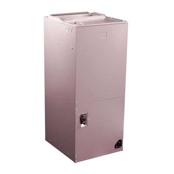
Product Specifications
WATPM Series Air Handler
2-3-4-5 Ton Capacity
Air Handler Features
Multi-speed ECM blower motor.
Factory-installed TXV metering.
Multipositlon Installation -.upflow or horizontal right standard;
field convertible to horizontal left or downflow.
Multiple electrical entry locations.
Field Installed heater kits 5, 8, 10, 15, 20KW available as an accessory.
Dual front panel design for ease of maintenance.
Blower and coil easy slide out design for ease of maintenance.
Fully-insulated cabinet design.
Horizontal and vertical condensate drain pans standard.
Condensate drain pan is polymer with UVC inhibitor.
Primary and secondary condensate drain fittings.
Factory-sealed cabinet certified to achieve 2% or less
leakage rate at 1.0 inch water column.
Integrated filter rack with tool-less door access.
AHRI and ETL Listed.
PARTS
5
LIMITED
YEAR
WARRANTY
1
R410A
R-410A
REFRIGERANT
Advertisement

Summary of Contents for Grandaire Pinnacle Series
-
Page 1: Table Of Contents
Product Specifications WATPM Series Air Handler 2-3-4-5 Ton Capacity R410A Air Handler Features Multi-speed ECM blower motor. Factory-installed TXV metering. Multipositlon Installation -.upflow or horizontal right standard; field convertible to horizontal left or downflow. Multiple electrical entry locations. Field Installed heater kits 5, 8, 10, 15, 20KW available as an accessory. Dual front panel design for ease of maintenance. -
Page 2: Nomenclature
Nomenclature PRODUCT SPECIFICATIONS FAN COIL MODEL NUMBER IDENTIFICATION GUIDE Digit Position: Example Part Number: WA = Air Handler T = TXV E = EEV P = High Efficency ECM Motor MOTOR TYPE S = PSC Motor L = Aluminum Tube,Aluminum Fin Evaporator Coil M = Copper Tube,Aluminum Fin Evaporator Coil... -
Page 3: Product Specifications
Product Specifications Specifications WATPM244A1 WATPM364A1 WATPM484A1 WATPM604A1 Cooling Capacity Nominal Cooling (BTU/h) 24,000 34,600 47,000 57,000 Nominal Heating (BTU/h) 24,000 33,600 46,500 55,000 Blower 10⅝" Diameter 11" 11" 11" 10⅝" 10⅝" 10⅝" Width 8" Fan Motor Horsepower (HP) Refrigeration System Refrigerant Line Size¹... -
Page 4: Dimensions
Dimensions NOTE: 25” CLEARANCE IS REQUIRED IN THE FRONT OF THE UNIT FOR FILTER AND COIL MAINTENANCE. HIGH VOLTAGE CONNECTION 7/8”, SUPPLY AIR FLANGES ARE PROVIDED 1-23/64”, 1-23/32” DIA KNOCK OUTS FOR FIELD INSTALLATION BREAKER SWITCH ( ELECTRIC HEATER ONLY) VAPOR LINE COPPER LIQUID LINE COPPER INLET... -
Page 5: Blower Data
Blower Data Airflow Performance Airflow performance data is based on cooling performance with a coil and no filter in place. Select performance table for appropriate unit size external static applied to unit allows operation within the minimum and maximum limits shown in table below for both cooling and electric heat operation. -
Page 6: Heater Kit Data
Heater Kit Data Electric Kit MCA/MOP Data MAX.Fuse or Breaker Fan speed MIN. Circuit Ampacity Heat Kit Air Handler (kW)Electric (HACR) Ampacity Model Model Heat • • • • • EHK05A 27.2 24.6 • • • 40.8 36.9 EHK08A • •... -
Page 7: Wiring Diagram
Wiring Diagram HIGH VOLTAGE! DISCONNECT ALL POWER BEFORE SERVICING OR INSTALLING THIS UNIT. MULTIPLE POWER SOURCES MAY BE PRESENT. FAILURE TO DO SO MAY CAUSE PROPERTY DAMAGE, PERSONAL INJURY OR DEATH. CAUTION: NOT SUITABLE FOR USE ON SYSTEMS EXCEEDING 150V TO GROUND ATTENTION: NE CONVIENT PAS AUXINSTALLATIONS DE PLUS DE 150V ALA TERRE PROHIBITED IN THIS STATE... - Page 8 Wiring Diagram Fig.4: Indoor Unit Wiring Diagram for Electric Heat. Wiring is subject to change. Always refer to the wiring diagram on the unit for the most up-to-date wiring. WARNING High Voltage: Disconnect all power before servicing or installing this unit. Multiple power sources may be present.
-
Page 9: Parts List
Parts List 24 25 26 27 14.4.2 14.4.1 14.4 14.3 14.2 14.1 Part Name 201270590079 201270890064 201270890064 201270890064 Top Pan, Cabinet 202301440007 202301440007 202301440007 202301440007 Ground Lug 201270490108 201270890101 201270890101 201270890101 Duct, Discharge 203370390083 203370390083 203370390083 203370390083 Main Control Board, Assy 201370390077 201370390077 201370390077... - Page 10 2020001C1080 V1.0...
Need help?
Do you have a question about the Pinnacle Series and is the answer not in the manual?
Questions and answers