Table of Contents

Summary of Contents for istobal Twash 4TA6000
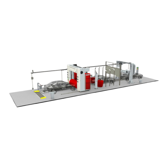
- Page 1 M O D . 4 T A 6 0 0 0 TRANSLATED FROM THE ORIGINAL MANUAL ISTOBAL, S.A. Avda. Conde del Serrallo, 10 46250 L’Alcúdia (Valencia - España) Teléfono 96 299 79 40 Fax 96 299 79 91 E-mail: istobal@istobal.com...
-
Page 2: Table Of Contents
34GJ100B I N D E X 1. SAFETY 2. BUILDING SPECIFICATIONS 2.1. Excavation work 2.2. Filling work and embankment 2.3. Bed 2.4. Reinforced concrete slab 2.5. Concrete specifications 2.6. Drainage gutters 2.7. Drainage piping 2.8. Rain gutters, with enclosure 3. EXCAVATION PLAN 3.1. -
Page 3: Safety
PREVENTIVE MEASURES ISTOBAL, S.A. personnel and workers subcontracted by the company are to take into account the following preventive measures while carrying out work: •... - Page 4 SAFETY PROTECTION EQUIPMENT Personal and collective protection equipment used should be appropriate to the task, certified with the mark, and display the corresponding inspection dates. Personal protection equipment should give effective protection against the risks they are intended for. Such equipment should not constitute a risk in itself nor cause unnecessary inconvenience.
- Page 5 SAFETY PERSONAL PROTECTION EQUIPMENT OTHER PROTECTION DEPENDING ON THE WORK TO BE DONE Tool belt. OTHER PROTECTION DEPENDING ON THE WORK TO BE DONE Safety harness. For work at a height of 2 m. and above. Back support belt. For tasks which require unusual positions to be adopt- ed, or straining.
- Page 6 SAFETY PERSONAL PROTECTION EQUIPMENT Welding screens and masks with metal smoke filter. Use of welding sets. COLLECTIVE PROTECTION EQUIPMENT Safety tape and cones To indicate and cordon off the work area. No entry sign. To prevent unauthorized access, and indicate the need for PPE to be worn.
-
Page 7: Building Specifications
BUILDING SPECIFICATIONS 2.1. Excavation work Any vegetation will be cleared, and any elements or small infrastructures will be removed, should there be any. The whole site will be cleared and the vegetation soil all over it will be removed. Once the desired level has been reached, soil moisture and compaction will be checked. 2.2. -
Page 8: Reinforced Concrete Slab
BUILDING SPECIFICATIONS • Granulometry - Fractions going through the 0.08 sieve will be smaller than half the fractions sieved with the 0.40 sieve. Measured by weight. - Maximum aggregate size will be smaller than half the compacted layer. - The fraction retained by Sieve 5 should at least have 50% (weight) elements with two or more fracture surfaces. -
Page 9: Concrete Specifications
BUILDING SPECIFICATIONS 2.5. Concrete specifications The slab concrete's corrosion exposure class is “IIa” (normal reinforcement for high moisture conditions). It is adequate for areas that are not by the sea. For other types of exposure, check regulations in force. Concerning exposure relating to concrete degradation phenomena other than corrosion, the concrete is ero- sion-classed, “E”. -
Page 10: Drainage Gutters
BUILDING SPECIFICATIONS • Aggregates - (Art. 37.3.7 EHE-08) - Fine aggregates will be QUARTZ or a material with at least the same hardness. - Los Angeles coefficient for thick aggregates under 30. - (Table 28.4.1.a. EHE-08) - Thick aggregates: maximum % passing through sieve 0.063: 1.5 %. -
Page 11: Drainage Piping
BUILDING SPECIFICATIONS 2.7. Drainage piping Gutter and central trap drainage is via a number of pipes that run along the boundaries of the wash tunnel. The pipes are PVC, with connection boxes and pits at intersection points where necessary. The pipework facilitates the drainage of water coming from the wash tunnel, taking it to the sludge settler, where water treatment starts for water to be recycled and reused in new wash processes. -
Page 12: Excavation Plan
EXCAVATION PLAN 3.1. No enclosure 15640 17360 18990 20610 22240 Measurements in mm. -
Page 13: With Enclosure
EXCAVATION PLAN 3.2. With enclosure 15640 17360 18990 20610 22240 Measurements in mm. -
Page 14: No Enclosure
NO ENCLOSURE 4.1. Design measurements and sections SECTION A - A’ B’ C’ D’ E’ A’ A Chain length 9290 10910 12540 14160 15790 B Bay length 15640 17360 18990 20610 22240 Measurements in mm. - Page 15 NO ENCLOSURE Concrete FCK=25 n/mm and Rebar mat 200x200x6 mm B500S Wet-mix macadam compacted SECTION B - B’ SECTION C - C’ SECTION D - D’ SECTION E - E’ INFORMATION » Surface of bay treated with non-slip finish. » Any guarantees as to the dimensions of the concrete beds depend on the floor being properly compacted.
-
Page 16: Electrical Lines
NO ENCLOSURE 4.2. Electrical lines Recommend- Minimum bay ed bay 4100 4500 2180 1980 Flexible PVC pipe D50 mm Flexible PVC pipe D50 mm Flexible PVC pipe D50 mm Flexible PVC pipe D50 mm Flexible PVC pipe D50 mm Flexible PVC pipe D90 mm Flexible PVC pipe D90 mm * PIPING FOR 15.8 M INSTALLATIONS ONLY, WITH SECOND DRYER AND POLISHING MODULE... -
Page 17: Air And Water Lines
NO ENCLOSURE 4.3. Air and water lines Water supply If only mains water is used, connect to either If recycled water is used, use connection point only. will be used for mains water or demineral- ised water. If mains water and demineralised water are used, will be used for mains water and connection point for demineralised water. -
Page 18: Dimensions
NO ENCLOSURE 4.4. Dimensions A Bay length 15640 17360 18990 20610 22240 Recommended 4500 4500 4500 4500 4500 Minimum 4100 4100 4100 4100 4100 C Chassis height 3087 3087 3087 3087 3087 D Max. vehicle height Recommended 2310 2310 2310 2310 2310 Minimum... - Page 19 NO ENCLOSURE Distances between modules can be seen on the layout drawing of each Tunnel. Measurements in mm.
-
Page 20: With Enclosure Mp
WITH ENCLOSURE MP 5.1. Design measurements and sections SECTION A - A’ B’ C’ D’ E’ A’ A Chain length 9290 10910 12540 14160 15790 B Bay length 15640 17360 18990 20610 22240 Measurements in mm. - Page 21 WITH ENCLOSURE MP Concrete FCK=25 n/mm and Rebar mat 200x200x6 mm B500S Wet-mix macadam compacted SECTION B - B’ SECTION C - C’ SECTION D - D’ SECTION E - E’ INFORMATION » Surface of bay treated with non-slip finish. »...
-
Page 22: Dimensions
WITH ENCLOSURE MP 5.2. Dimensions A Bay length 15640 17360 18990 20610 22240 Recommended 4500 4500 4500 4500 4500 Minimum 4100 4100 4100 4100 4100 C Chassis height 3087 3087 3087 3087 3087 D Max. vehicle height Recommended 2310 2310 2310 2310 2310... - Page 23 WITH ENCLOSURE MP Distances between modules can be seen on the layout drawing of each Tunnel. Measurements in mm.
-
Page 24: Electrical Lines
WITH ENCLOSURE MP 5.3. Electrical lines Recommend- Minimum bay ed bay 4100 4500 2180 1980 Flexible PVC pipe D50 mm Flexible PVC pipe D50 mm Flexible PVC pipe D50 mm Flexible PVC pipe D50 mm Flexible PVC pipe D50 mm Flexible PVC pipe D90 mm Flexible PVC pipe D90 mm * PIPING FOR 15.8 M INSTALLATIONS ONLY, WITH... -
Page 25: Air And Water Lines
WITH ENCLOSURE MP 5.4. Air and water lines Water supply If only mains water is used, connect to either If recycled water is used, use connection point only. will be used for mains water or demineral- ised water. If mains water and demineralised water are used, will be used for mains water and connection point for demineralised water. -
Page 26: With Enclosure Cm
WITH ENCLOSURE CM 6.1. Design measurements and sections SECTION A - A’ B’ C’ D’ E’ A’ A Chain length 9290 10910 12540 14160 15790 B Bay length 15640 17360 18990 20610 22240 Measurements in mm. - Page 27 WITH ENCLOSURE CM Concrete FCK=25 n/mm Continuous reinforcing armature 200x200x12 mm B500S Blinding concrete FCK 10n/mm thickness = 100mm SECTION B - B’ SECTION C - C’ SECTION D - D’ SECTION E - E’ INFORMATION » Surface of bay treated with non-slip finish. »...
-
Page 28: Adjoining Bays
WITH ENCLOSURE CM 6.1. Adjoining bays... - Page 29 WITH ENCLOSURE CM Concrete FCK=25 n/mm Continuous reinforcing armature 200x200x12 mm B500S Blinding concrete FCK 10n/mm thickness = 100mm SIDE REINFORCEMENT Upper reinforcement: Transversal: Ø12 c/200mm. Longitudinal: 6Ø12 Longitudinal beam: Dimensions: 400x300 mm. Reinforcement: 4Ø12, edges Ø8 c/300mm Lower reinforcement: Transversal: Ø12 c/200mm.
-
Page 30: Dimensions
WITH ENCLOSURE CM 6.2. Dimensions A Bay length 15640 17360 18990 20610 22240 Recommended 4500 4500 4500 4500 4500 Minimum 4100 4100 4100 4100 4100 C Chassis height 3087 3087 3087 3087 3087 D Max. vehicle height Recommended 2310 2310 2310 2310 2310... - Page 31 WITH ENCLOSURE CM Distances between modules can be seen on the layout drawing of each Tunnel. Measurements in mm.
-
Page 32: Electrical Lines
WITH ENCLOSURE CM 6.1. Electrical lines Recommend- Minimum bay ed bay 4100 4500 2180 1980 Flexible PVC pipe D50 mm Flexible PVC pipe D50 mm Flexible PVC pipe D50 mm Flexible PVC pipe D50 mm Flexible PVC pipe D50 mm Flexible PVC pipe D90 mm Flexible PVC pipe D90 mm * PIPING FOR 15.8 M INSTALLATIONS ONLY, WITH... -
Page 33: Air And Water Lines
WITH ENCLOSURE CM 6.1. Air and water lines Water supply If only mains water is used, connect to either If recycled water is used, use connection point only. will be used for mains water or demineral- ised water. If mains water and demineralised water are used, will be used for mains water and connection point for demineralised water. -
Page 34: Connection Details
DETAILS DETAIL X DETAIL Y Rail supplied by Istobal LPN 30x3 mm With corrosion primer This profile is fitted all along the contour marked with a double line in HEA Section 100x2840 the next drawing. Not supplied by Istobal Detail W... - Page 35 DETAILS Note...
-
Page 36: Installation
INSTALLATION... - Page 37 INSTALLATION...
-
Page 38: Electrical Data
INSTALLATION... -
Page 39: Electrical Distribution Cabinet
INSTALLATION...
Need help?
Do you have a question about the Twash 4TA6000 and is the answer not in the manual?
Questions and answers