Table of Contents
Advertisement
Quick Links
Bin Stairs
MFS | Stormor 2.66" Corrugation Grain Bins
Construction and Maintenance Manual
This manual applies to:
Bin Wall Sheet: 32" [813 mm], 42" [1,067 mm]
Original Instructions
Read this manual before using product. Failure to
follow instructions and safety precautions can
result in serious injury, death, or property
damage. Keep manual for future reference.
GRAIN BIN SPIRAL STAIR
INSTALLATION AND STORAGE
INSTRUCTIONS
READ THESE INSTRUCTIONS CAREFULLY AND COMPLETELY
BEFORE BEGINNING ASSEMBLY OF GRAIN BIN
EFFECTIVE DATE: November, 2015
Part Number: 198889
Revision: 4
Part Number: 4000051 R0
Revised: 2018–09Sept-20
Advertisement
Table of Contents

Summary of Contents for Brownie MFS Bin Stairs
- Page 1 Bin Stairs MFS | Stormor 2.66” Corrugation Grain Bins Construction and Maintenance Manual Part Number: 198889 Revision: 4 This manual applies to: GRAIN BIN SPIRAL STAIR Bin Wall Sheet: 32” [813 mm], 42” [1,067 mm] INSTALLATION AND STORAGE Original Instructions INSTRUCTIONS READ THESE INSTRUCTIONS CAREFULLY AND COMPLETELY BEFORE BEGINNING ASSEMBLY OF GRAIN BIN...
- Page 2 New in this Manual The following changes have been made in this revision of the manual: Description Section Modified manual format. All sections New platform-to-stairs elbows replaced old ones. Assembly The length of stairs posts was increased. Assembly...
-
Page 3: Table Of Contents
BIN STAIRS – MFS | STORMOR 2.66” CORRUGATION GRAIN BINS CONTENTS 1. Introduction ............................5 2. Safety............................... 6 2.1. Safety Alert Symbol and Signal Words..................6 2.2. General Safety .......................... 6 2.3. Auxiliary Equipment Safety ...................... 6 2.4. Personal Protective Equipment....................7 2.5. - Page 4 BIN STAIRS – MFS | STORMOR 2.66” CORRUGATION GRAIN BINS 4.13.1 Single Top Landing Assembly ................. 93 4.13.2 1-Ring Stair Bundle Assembly ................96 4.13.3 Intermediate Platform Assembly (Optional)............99 4.13.4 Bottom Ring Stair Bundle Assembly ..............102 5. Maintenance ............................105 5.1.
-
Page 5: Introduction
BIN STAIRS – MFS | STORMOR 2.66” CORRUGATION GRAIN BINS 1. Introduction This manual describes how to assemble a Brownie Bin Stairs. Before assembling the bin stairs, please read this manual. Familiarize yourself with the process and the necessary precautions for efficient and safe assembly. -
Page 6: Safety
• Obtain, read, and understand the instructions and safety warnings of the auxiliary equipment manufacturer. • Check with Brownie or your dealer to make certain this bin stairs is designed to support any additional loads supplied by the auxiliary equipment. -
Page 7: Personal Protective Equipment
2. SAFETY BIN STAIRS – MFS | STORMOR 2.66” CORRUGATION GRAIN BINS 2.4. Personal Protective Equipment The following Personal Protective Equipment (PPE) should be worn when assembling the equipment. Safety Glasses • Wear safety glasses at all times to protect eyes from debris. Coveralls •... -
Page 8: Features
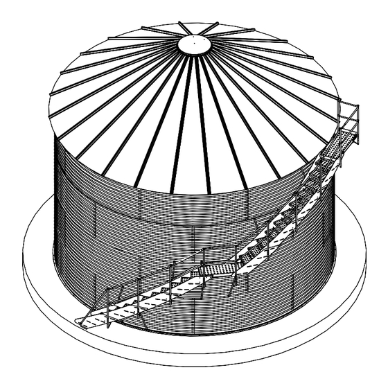
3. FEATURES BIN STAIRS – MFS | STORMOR 2.66” CORRUGATION GRAIN BINS 3. Features This section covers the main features of the bin stairs. Figure 1. Typical Bin Stairs GRAIN BIN ROOF ROOF LADDER MANWAY SINGLE LANDING 1-RING SECTIONS INTERMEDIATE GRAIN BIN PLATFORM BIN WALL... -
Page 9: Assembly
Important Do not assemble or install damaged components. 4.3. Product Storage Brownie Bin Stairs parts should be stored in a clean, dry location to prevent rust and corrosion of steel components. For outdoor storage, protection should be provided. Rust on Galvanized Parts 1. -
Page 10: Component Locations
Due to safety concerns with installation and use, Brownie does not recommend the use of oil on other parts such as roof sheets, rungs, treads, and platforms. 4. If moisture is left on parts, this white rust can become more aggressive and turn into red rust. Red rust can cause degradation in the material and become a structural concern. -
Page 11: Before You Begin
4. ASSEMBLY BIN STAIRS – MFS | STORMOR 2.66” CORRUGATION GRAIN BINS 4.5. Before You Begin Before you assemble the bin stairs: • Familiarize yourself with all the sub-assemblies, components, and hardware that make up the equipment. • Have all parts and components on hand, and arrange them for easy access. •... -
Page 12: Single Top Landing
4. ASSEMBLY BIN STAIRS – MFS | STORMOR 2.66” CORRUGATION GRAIN BINS 4.7. Single Top Landing Figure 2. Single Top Landing Overview RAILING LANDING - Single Top Landing - Bundle PLATFORM END CAP END RAIL ELBOW 32”: 24’ - 36’ bins - 4503455 P-STRAP POST 1896001... - Page 13 4. ASSEMBLY BIN STAIRS – MFS | STORMOR 2.66” CORRUGATION GRAIN BINS Figure 3. Single Top Landing Exploded View ALIGN POST HOLES AS SHOWN. HANDRAIL POST RAILING 3498253 END CAP 1896001 LANDING - INNER TOE BOARD SPLICE 3498277 LANDING - LANDING OBTUSE ELBOW END RAIL ELBOW 32”...
-
Page 14: Single Top Landing Platform Location
4. ASSEMBLY BIN STAIRS – MFS | STORMOR 2.66” CORRUGATION GRAIN BINS 4.7.1 Single Top Landing Platform Location 1. Locate the single top landing mounting holes. 2. Position the platform under the manway or the roof stairs. 3. Drop a plumb line from (2) predetermined eave ring bolts. Drill (4) 7/16” [12 mm] holes in the locations shown in Figure 4 Figure... - Page 15 4. ASSEMBLY BIN STAIRS – MFS | STORMOR 2.66” CORRUGATION GRAIN BINS Figure 5. Platform Anchor Layout for 42” [1,067 mm] Bin Wall manway typical roof steps location for single top landing or double top landing 3 1/8” [79 mm] eave ring bolts at (shown) predetermined locations...
-
Page 16: Single Top Landing Assembly
4. ASSEMBLY BIN STAIRS – MFS | STORMOR 2.66” CORRUGATION GRAIN BINS 4.7.2 Single Top Landing Assembly Install the Bin Anchors 1. Position (2) bin anchors in the locations shown in Figure 6 Figure 2. Install bin anchors to the bin wall through the bin anchor center hole. Use 3/8” x 1-1/4” bin bolts and flange nuts. - Page 17 4. ASSEMBLY BIN STAIRS – MFS | STORMOR 2.66” CORRUGATION GRAIN BINS Install the End Toe Board Important Before starting platform assembly, determine whether the bin stairs will ascend from the right or left. After determination, start platform assembly. 1. Install the end toe board, inner toe board splice, and outer toe board splice. Figure 8.
- Page 18 4. ASSEMBLY BIN STAIRS – MFS | STORMOR 2.66” CORRUGATION GRAIN BINS Install the Connection Plates and Stringers 1. Locate and install the inner and outer connection plates and stringers. 2. Install these plates to the platform and to each other. Use 3/8” x 1-1/4” bin bolts and nuts. Figure 9.
- Page 19 4. ASSEMBLY BIN STAIRS – MFS | STORMOR 2.66” CORRUGATION GRAIN BINS Figure 10. Installing the Connection Plates and Stringers — 42” [1,067 mm] Bin Wall TOP LANDING (landing) INNER CONNECTION PLATE 3498318 3/8” x 1 1/4” OUTER BIN BOLT CONNECTION PLATE 004182 3498319...
-
Page 20: Single Top Landing To Bin Wall
4. ASSEMBLY BIN STAIRS – MFS | STORMOR 2.66” CORRUGATION GRAIN BINS 4.7.3 Single Top Landing To Bin Wall 1. Install the landing platform to the already-installed bin anchors. Use 3/8” x 1” bin bolts to install the landing platform using the lower (2) bin anchor holes. Tighten nuts. 2. -
Page 21: Single Top Landing Handrail Assembly
4. ASSEMBLY BIN STAIRS – MFS | STORMOR 2.66” CORRUGATION GRAIN BINS 4.7.4 Single Top Landing Handrail Assembly P-Strap Connections 1. Slide the “P” straps over the elbows. See now Figure 13 Figure 2. Install the straps to the posts with 3/8” carriage bolts, nuts, and lock washers. Check that the “P”... - Page 22 4. ASSEMBLY BIN STAIRS – MFS | STORMOR 2.66” CORRUGATION GRAIN BINS Install the Handrails 1. Install the end rail elbows as shown in Figure Figure 13. Installing the End Platform Handrail END RAIL ELBOW HANDRAIL “P” STRAP 3498275 3498257 CONDUIT CAP 1896001 PLATFORM...
-
Page 23: Complete The Single Top Landing Assembly
4. ASSEMBLY BIN STAIRS – MFS | STORMOR 2.66” CORRUGATION GRAIN BINS 2. Install the platform handrail elbows and obtuse elbows as shown in Figure Figure 14. Installing the Platform Elbows HANDRAIL POST OBTUSE ELBOW, 3498253 32” bin wall: 3498372, 42”... - Page 24 4. ASSEMBLY BIN STAIRS – MFS | STORMOR 2.66” CORRUGATION GRAIN BINS 13. Install the bin anchor to the inner connection stringer lower end and to the bin sidewall. 14. Install the handrail posts, and bin stair braces to the outer connection stringer. 15.
-
Page 25: 1-Ring Stair Sections
4. ASSEMBLY BIN STAIRS – MFS | STORMOR 2.66” CORRUGATION GRAIN BINS 4.8. 1-Ring Stair Sections Figure 16. 1-Ring Stair Section, 32” [813 mm] Bin Wall, Overview HANDRAIL 32” BIN WALL 1-Ring Section, 32” Bin Wall - Bundle 15’ - 21’ DIAMETERS - 3498261 15’... - Page 26 4. ASSEMBLY BIN STAIRS – MFS | STORMOR 2.66” CORRUGATION GRAIN BINS Figure 17. 1-Ring Stair Section, 42” [1,067 mm] Bin Wall, Overview OUTER STRINGER, HANDRAIL 42” BIN WALL 42” BIN WALL 15’ - 21’ DIAMETERS - 3498315 3498311 24’ - 33’ DIAMETERS - 3498316 36’...
-
Page 27: 1-Ring Stair Sections Anchor Layouts
4. ASSEMBLY BIN STAIRS – MFS | STORMOR 2.66” CORRUGATION GRAIN BINS 4.8.1 1-Ring Stair Sections Anchor Layouts 1. Position the bin anchors as shown in Figure 18 Figure Note Whether the bin is a new installation or one already built, either add or remove bin bolts as required. - Page 28 4. ASSEMBLY BIN STAIRS – MFS | STORMOR 2.66” CORRUGATION GRAIN BINS Figure 19. Anchor Layout for 42” [1,067 mm] Bin Wall 4 or 12 bolts over 3 1/2 or 10 1/2 bolts over “ “ 4 or 12 bolts over [953 mm] [953 mm] 3 1/8”...
-
Page 29: 1-Ring Stair Sections Assembly
4. ASSEMBLY BIN STAIRS – MFS | STORMOR 2.66” CORRUGATION GRAIN BINS 4.8.2 1-Ring Stair Sections Assembly Install the Bin Anchors 1. Position and install intermediate anchors through the anchor middle-hole. See Figure Figure 20. Intermediate Anchor bin wall bolt seam 2. - Page 30 4. ASSEMBLY BIN STAIRS – MFS | STORMOR 2.66” CORRUGATION GRAIN BINS Install the Inner Stringers Note One (1) inner stringer covers one (1) sidewall sheet vertical distance. 1. Connect inner stringers together. 2. Bolt through the top (2) lower stringer slots and upper stringer bottom-most slots. Use 3/8” x 1-1/4” bolts and flange nuts.
- Page 31 4. ASSEMBLY BIN STAIRS – MFS | STORMOR 2.66” CORRUGATION GRAIN BINS Figure 23. Inner Stringers Connection, 42” [1,067 mm] Bin Wall NOTE: WHEN INSTALLING HARDWARE, MAKE CERTAIN THE BOLT SHANKS FACE AWAY FROM THE TREAD SIDE. INNER STRINGER 3498310 3/8”...
- Page 32 4. ASSEMBLY BIN STAIRS – MFS | STORMOR 2.66” CORRUGATION GRAIN BINS Table 1. Outer Stringers Connection per Bin Size 32” [813 mm] Bin Wall 42” [1,067 mm] Bin Wall Bin size OUTER STRINGER OUTER STRINGER 3498311 3498346 15’ - 18’ (4.57 m —...
- Page 33 4. ASSEMBLY BIN STAIRS – MFS | STORMOR 2.66” CORRUGATION GRAIN BINS Figure 25. Outer Stringers Connection, 42” [1,067 mm] Bin Wall h) Outer Stringers Connections NOTE: When installing hardware, make certain the bolt shanks face away from the tread side. 3/8”...
- Page 34 4. ASSEMBLY BIN STAIRS – MFS | STORMOR 2.66” CORRUGATION GRAIN BINS Install Stairs Assembly to the Bin Wall 1. Connect the inner connection plate to an inner connection stringer (or 2 inner connection stringers bolted together, see Figure 26.) 2.
- Page 35 4. ASSEMBLY BIN STAIRS – MFS | STORMOR 2.66” CORRUGATION GRAIN BINS Install the Steps and Outer Stringers 1. Bolt a few stair steps to the inner stringers. Use 3/8” x 1-1/4” bin bolts and flange nuts. 2. Fasten the outer stringers to the steps and to the outside of the outer connection plate. Figure 27.
- Page 36 4. ASSEMBLY BIN STAIRS – MFS | STORMOR 2.66” CORRUGATION GRAIN BINS Figure 28. Attaching Outer Stringers to Steps, 42” [1,067 mm] Bin Wall (The bin wall is not shown in this illustration for clarity.) OUTER CONNECTION PLATE 3498319 INNER CONNECTION PLATE 3498318 INNER...
-
Page 37: 1-Ring Stair Sections Handrail Assembly
4. ASSEMBLY BIN STAIRS – MFS | STORMOR 2.66” CORRUGATION GRAIN BINS 4.8.3 1-Ring Stair Sections Handrail Assembly Install the First Post 1. Install the first post at the connection plate. Use 3/8” x 1-1/4” bin bolts and flange nuts. 2. - Page 38 4. ASSEMBLY BIN STAIRS – MFS | STORMOR 2.66” CORRUGATION GRAIN BINS Install the Succeeding Posts and Braces 1. Install posts and braces at the locations across from the anchors (which are connected to the inner stringers). Use 3/8” x 2” bolts and flange nuts. 2.
- Page 39 4. ASSEMBLY BIN STAIRS – MFS | STORMOR 2.66” CORRUGATION GRAIN BINS Install the Handrails Figure 31. Installing the Handrails PLATFORM HANDRAIL POST 3498253 HANDRAIL POST 3498371 HANDRAIL MIDRAIL 4000051 R0...
- Page 40 4. ASSEMBLY BIN STAIRS – MFS | STORMOR 2.66” CORRUGATION GRAIN BINS Figure 32. OSHA Vertical Distance Measured from the Top Front of the Step Walking Surface 36” - 38” [914 mm - 965 mm] 4000051 R0...
-
Page 41: Bottom Ring Stair Sections
4. ASSEMBLY BIN STAIRS – MFS | STORMOR 2.66” CORRUGATION GRAIN BINS 4.9. Bottom Ring Stair Sections Figure 33. Bottom Ring Stair Section Overview, 32” [813 mm] Bin Wall Bottom Ring Section, 32” Bin Wall - Bundle 4503450 HANDRAIL, 32” BIN WALL, 15’... - Page 42 4. ASSEMBLY BIN STAIRS – MFS | STORMOR 2.66” CORRUGATION GRAIN BINS Figure 34. Bottom Ring Stair Section, 42” [1,067 mm] Bin Wall HANDRAIL 36’ [10.97 mm] - 54’ [16.46 mm] DIAMETERS 3498263 HANDRAIL OUTER STRINGER, 36’ [10.97 mm] - 54’ [16.46 mm] 42”...
-
Page 43: Bottom Ring Stair Sections And Handrail Assembly
4. ASSEMBLY BIN STAIRS – MFS | STORMOR 2.66” CORRUGATION GRAIN BINS 4.9.1 Bottom Ring Stair Sections and Handrail Assembly Install the Bottom Stair Section and Handrail 1. Install the bottom stair section in the same manner as the other stair sections were installed. 2. - Page 44 3/8” concrete anchor (not included with the bin stairs package). Figure 36. Installing the Bottom Handrail Post BOTTOM HANDRAIL POST 3498373 HANDRAIL POST ANCHOR 3498256 Connection to concrete, 3/8” anchor not supplied by Brownie 4000051 R0...
-
Page 45: Completed Bottom Ring Stair Section, 32" [813 Mm] Wall
4. ASSEMBLY BIN STAIRS – MFS | STORMOR 2.66” CORRUGATION GRAIN BINS 4.9.2 Completed Bottom Ring Stair Section, 32” [813 mm] Wall INNER STRINGER, 32” BIN WALL HANDRAIL STEP BIN ANCHOR BOTTOM ELBOW BOTTOM HANDRAIL POST BIN STAIR OUTER STRINGER, BRACE 32”... -
Page 46: Double Top Landing
4. ASSEMBLY BIN STAIRS – MFS | STORMOR 2.66” CORRUGATION GRAIN BINS 4.10. Double Top Landing Figure 37. Double Top Landing Overview LANDING - END LANDING - END DOUBLE LANDING LANDING - OUTER RAIL ELBOW TOE BOARD HANDRAIL EXTENSION TOE BOARD SPLICE 3498275 3498276 3498279... -
Page 47: Double Top Landing Platform Location
4. ASSEMBLY BIN STAIRS – MFS | STORMOR 2.66” CORRUGATION GRAIN BINS 4.10.1 Double Top Landing Platform Location 1. Position the platform under the manway and roof stairs. 2. Drop a plumb line from the (4) predetermined eave ring bolts. 3. - Page 48 4. ASSEMBLY BIN STAIRS – MFS | STORMOR 2.66” CORRUGATION GRAIN BINS Figure 39. Anchor Layout, 42” [1,067 mm] Bin Wall manway typical roof steps location for single top landing or double top landing 3 1/8” [79 mm] eave ring bolts at (shown) predetermined locations 8”...
-
Page 49: Double Top Landings Assembly
4. ASSEMBLY BIN STAIRS – MFS | STORMOR 2.66” CORRUGATION GRAIN BINS 4.10.2 Double Top Landings Assembly Assemble the Platform Note Double Top Landings are installed using the same procedure as is used for installing Single Top Landings. Double Top Landings have 2 platform bases and Single Top Landings have 1 platform base. This is the main difference between these 2 platforms. - Page 50 4. ASSEMBLY BIN STAIRS – MFS | STORMOR 2.66” CORRUGATION GRAIN BINS Figure 41. Install the Bin Stair Braces and Posts 42’-105’ [12.80 m - 32.00 m] PLATFORM LANDING HANDRAIL POST PLATFORM BASE 3498253 3498276 BIN STAIR BRACE 32” BIN WALL 3498333 42”...
- Page 51 4. ASSEMBLY BIN STAIRS – MFS | STORMOR 2.66” CORRUGATION GRAIN BINS Figure 42. Connect the Platforms Together to bin wall 3/8” x 1” BIN BOLT and FLANGE NUT Figure 43. Installing the Landing Splices TOE BOARD SPLICE, 3498280 6. See Section 4.7.2 –...
-
Page 52: Install The Double Platform Handrail Extensions
4. ASSEMBLY BIN STAIRS – MFS | STORMOR 2.66” CORRUGATION GRAIN BINS 4.10.3 Install the Double Platform Handrail Extensions Add the double landing handrail extensions as shown in Figure 44. Once installed, refer back to Section 4.7.3 – Single Top Landing To Bin Wall on page 20 and for the rest of the handrail installation. -
Page 53: Intermediate Platform (Optional)
4. ASSEMBLY BIN STAIRS – MFS | STORMOR 2.66” CORRUGATION GRAIN BINS 4.11. Intermediate Platform (Optional) Note This is an optional platform and is not used on every installation. Do not install the top landing at the intermediate location. Figure 45. Intermediate Platform Overview Intermediate Platform Section, Bundle OUTER CONNECTION... -
Page 54: Intermediate Platform Location
4. ASSEMBLY BIN STAIRS – MFS | STORMOR 2.66” CORRUGATION GRAIN BINS 4.11.1 Intermediate Platform Location 1. Predetermine the position for the intermediate platform(s) using Figure 46 as a guide for placement. Figure 46. Typical Intermediate Platform Layout TOP LANDING anchor “A”... - Page 55 4. ASSEMBLY BIN STAIRS – MFS | STORMOR 2.66” CORRUGATION GRAIN BINS 2. Starting at the last upper anchor position before the intermediate platform, the first intermediate platform anchor will be located (4) bolts over, (1) sheet down, then (3) corrugation “hills” or 8” [203 mm] up. Platform bin stair braces hole locations will be down either 32”...
-
Page 56: Intermediate Platform Assembly
4. ASSEMBLY BIN STAIRS – MFS | STORMOR 2.66” CORRUGATION GRAIN BINS 4.11.2 Intermediate Platform Assembly Install the Bin Anchors 1. Install the lower anchors to the sidewall. 2. The first anchor after the platform anchors will be located (3) corrugation “hills” down and (1) bolt over. Anchors thereafter will again follow the “(4) bolts over, (1) ring down”... - Page 57 4. ASSEMBLY BIN STAIRS – MFS | STORMOR 2.66” CORRUGATION GRAIN BINS Install the Intermediate Platform and Stringers 1. Install the intermediate platform to the anchors. 2. Install (1) step along with the intermediate platform stringers. Connect the platform base to the stair section as shown in Figure Figure 49.
-
Page 58: Intermediate Platform Handrail Assembly
4. ASSEMBLY BIN STAIRS – MFS | STORMOR 2.66” CORRUGATION GRAIN BINS 4.11.3 Intermediate Platform Handrail Assembly Install Handrail Posts and Braces 1. Install the handrail posts and bin stair braces to the platform (outer side). See Figure 50. Use 3/8” x 2” flange bolts and hex nuts to install the posts and braces. - Page 59 4. ASSEMBLY BIN STAIRS – MFS | STORMOR 2.66” CORRUGATION GRAIN BINS Note The 18” [457 mm] splice (3498284) may require trimming. Figure 51. 18” [457 mm] Splice 18” [457 mm] Figure 52. Installing the Handrails HANDRAIL POST INTERMEDIATE PLATFORM 3498371 OBTUSE ELBOW 18”...
-
Page 60: Completed Intermediate Platform
4. ASSEMBLY BIN STAIRS – MFS | STORMOR 2.66” CORRUGATION GRAIN BINS 4.11.4 Completed Intermediate Platform STEP 18” HANDRAIL SPLICE INNER INTERMEDIATE PLATFORM STRINGER OBTUSE ELBOW BIN ANCHOR OBTUSE ELBOW INNER CONNECTION PLATE BIN STAIR BRACE OUTER INTERMEDIATE PLATFORM STRINGER LANDING (platform) OUTER CONNECTION PLATE 4000051 R0... -
Page 61: Crossover Platforms
4. ASSEMBLY BIN STAIRS – MFS | STORMOR 2.66” CORRUGATION GRAIN BINS 4.12. Crossover Platforms Figure 53. Short Crossover Platform Overview HANDRAIL TUBE, STEP OVER RAILING END CAP 60” [1,524 mm] PLATFORM BASE 1896001 3498295 3498293 P-STRAP 3498257 PLATFORM HANDRAIL 90°... -
Page 62: Plan Bin Foundation Layout
4. ASSEMBLY BIN STAIRS – MFS | STORMOR 2.66” CORRUGATION GRAIN BINS 4.12.1 Plan Bin Foundation Layout Accurately plan the bin foundations layout before starting bin foundations construction. Design the foundations layout so the Step Over Platform will fit correctly between the (2) bins. Use the following formula to obtain the correct positions for the bin wall circles: [Actual Bin Radius #1 + Actual Bin Radius #2 + 62-1/4”... - Page 63 4. ASSEMBLY BIN STAIRS – MFS | STORMOR 2.66” CORRUGATION GRAIN BINS Customary Units • Up to 60’ Diameter Bin: Bin #1 Radius + Bin #2 Radius + 62-1/4” +1” -2” + 1/2” • 75’ to 105’ Diameter Bin: Bin #1 Radius + Bin #2 Radius + 84-1/4” +1”...
-
Page 64: Crossover Platform Base Installation To Bin #2
4. ASSEMBLY BIN STAIRS – MFS | STORMOR 2.66” CORRUGATION GRAIN BINS 4.12.2 Crossover Platform Base Installation to Bin #2 Note Install the crossover platform to bin number 2 after the first (2) bin sidewall rings have been constructed and before raising the bin. 1. - Page 65 4. ASSEMBLY BIN STAIRS – MFS | STORMOR 2.66” CORRUGATION GRAIN BINS Figure 58. Crossover Platform Drill Hole Locations, 32” [813 mm] Bin Wall manway roof steps eave ring bolts at predetermined locations 9 3/8” [238 mm] (shown) 8” [203 mm] drill 32”...
- Page 66 4. ASSEMBLY BIN STAIRS – MFS | STORMOR 2.66” CORRUGATION GRAIN BINS Figure 59. Crossover Platform Drill Locations, 42” [1,067 mm] Bin Wall eave ring bolts at manway predetermined locations roof steps 3 1/8” [79 mm] (shown) 8” [203 mm] drill 32”...
-
Page 67: Crossover Platform Assembly
4. ASSEMBLY BIN STAIRS – MFS | STORMOR 2.66” CORRUGATION GRAIN BINS 4.12.3 Crossover Platform Assembly • Do not stand on the crossover platform and stairs (or under them) until the crossover platform installation is completely installed and structurally secured to both bins. Safely and securely support the platforms and stairs assemblies during construction. - Page 68 4. ASSEMBLY BIN STAIRS – MFS | STORMOR 2.66” CORRUGATION GRAIN BINS Figure 61. Installing the Bin Anchors to the Bin Wall ROOF LADDER BIN ANCHOR 3498313 3/8” x 1 1/4” BIN BOLT 004182 and FLANGE NUT 90005027 4000051 R0...
- Page 69 4. ASSEMBLY BIN STAIRS – MFS | STORMOR 2.66” CORRUGATION GRAIN BINS Install the Gusset Tubes Install the platform gusset tubes to the (2) lower drill hole locations, see Figure Figure 62. Installing the Gusset Tubes to the Bin Wall BIN WALL ROOF LADDER...
- Page 70 4. ASSEMBLY BIN STAIRS – MFS | STORMOR 2.66” CORRUGATION GRAIN BINS Install the Platform Base Installation 1. Install the platform base to the bin anchors and platform gusset tubes as shown in Figure Figure 63. Installing the Platform Base ROOF LADDER 3/8”...
-
Page 71: Short Crossover Assembly
4. ASSEMBLY BIN STAIRS – MFS | STORMOR 2.66” CORRUGATION GRAIN BINS 4.12.4 Short Crossover Assembly Raise Bin #1 to its final Height Section 4.12.1 – Plan Bin Foundation Layout on page Install the Toe Board Install the toe board to the platform base, see Figure 64. - Page 72 4. ASSEMBLY BIN STAIRS – MFS | STORMOR 2.66” CORRUGATION GRAIN BINS Install the Stringer Connection Plates Install the stringer connection plates to the platform base, see Figure 65. Use 3/8” x 1 1/4” bin bolts and flange nuts. Figure 65. Installing the Stringer Connection Plates 3/8”...
- Page 73 4. ASSEMBLY BIN STAIRS – MFS | STORMOR 2.66” CORRUGATION GRAIN BINS Install the Posts and End Handrails 1. Install the handrail posts and post extensions to the platform base as shown. See Figure 2. Install the end handrail using P-straps and 3/8” x 1-1/2” carriage bolts and flange nuts. 3.
- Page 74 4. ASSEMBLY BIN STAIRS – MFS | STORMOR 2.66” CORRUGATION GRAIN BINS Install Post Gusset Tubes Install the post gusset tubes to the post extensions lower-ends and the channels on the platform base bottom, Figure 67. Use 3/8” x 1 1/4” bin bolts and flange nuts. Figure 67.
- Page 75 4. ASSEMBLY BIN STAIRS – MFS | STORMOR 2.66” CORRUGATION GRAIN BINS Complete the Crossover Assembly 1. Install side entry handrails. a. Install the 90° handrails and 54° handrail elbows at the platform entry side using P - straps, 3/8” x 1-1/2” carriage bolts, and flange nuts.
- Page 76 4. ASSEMBLY BIN STAIRS – MFS | STORMOR 2.66” CORRUGATION GRAIN BINS Figure 69. Swaged Handrail Connections, Tek Screws 2. Install upper bin stairs to the crossover platform. See Figure 68 on page 75 Figure 73 on page 79 complete this installation. Make certain the crossover platform is safely and securely supported for raising along with bin #2.
- Page 77 4. ASSEMBLY BIN STAIRS – MFS | STORMOR 2.66” CORRUGATION GRAIN BINS 5. Connect the adjustable anchors. a. Install adjustable anchors to complete the connection between bin #1 and the crossover platform. b. Tighten the anchor bolts so the anchors rest tight up against the bin wall and tight against the crossover platform.
- Page 78 4. ASSEMBLY BIN STAIRS – MFS | STORMOR 2.66” CORRUGATION GRAIN BINS b. Drill the holes in the bin wall to connect the bin #1 platform gusset tubes to bin #1. Use 3/8” x 1-1/4” bolts and flange nuts at both of these connections. Figure 72.
- Page 79 4. ASSEMBLY BIN STAIRS – MFS | STORMOR 2.66” CORRUGATION GRAIN BINS Figure 73. Completed Short Crossover Platform Bin #2 is not shown in this illustration for clarity. 4000051 R0...
-
Page 80: Short Crossover With Double Landing Assembly
4. ASSEMBLY BIN STAIRS – MFS | STORMOR 2.66” CORRUGATION GRAIN BINS 4.12.5 Short Crossover with Double Landing Assembly Before Installing the Platform • Make an accurate layout plan drawing for the bin #1 and bin #2 foundations and the short crossover platform assembly. - Page 81 4. ASSEMBLY BIN STAIRS – MFS | STORMOR 2.66” CORRUGATION GRAIN BINS Figure 74. Short Crossover with Double Landing Components CROSSOVER ELBOW OUTER PLATFORM P-STRAP HANDRAIL POST POST 72’-105’ [21.94 m-32.00 m] TOE BOARD HANDRAIL POST 3498257 3498295 EXTENSION GUSSET TUBE 3498354 SPLICE 3498253...
- Page 82 4. ASSEMBLY BIN STAIRS – MFS | STORMOR 2.66” CORRUGATION GRAIN BINS the short crossover platform base must be safely and securely supported during construction and while bin #2 is being raised. 5. Install bin stair braces, platform gusset tubes, and handrail posts to support the bin #2 landing platform base.
- Page 83 4. ASSEMBLY BIN STAIRS – MFS | STORMOR 2.66” CORRUGATION GRAIN BINS Figure 75. Completed Short Crossover with Double Landing PLATFORM CROSSOVER ELBOW HANDRAIL POST P-STRAP HANDRAIL 3498253 72’-105’ [21.94 m-32.00 m] 3498257 3498295 3498354 (fi eld cut to POST necessary length) EXTENSION 3498304...
-
Page 84: Extended Crossover Assembly
4. ASSEMBLY BIN STAIRS – MFS | STORMOR 2.66” CORRUGATION GRAIN BINS 4.12.6 Extended Crossover Assembly Before Installing the Platform • Make an accurate layout plan drawing for the bin #1 and bin #2 foundations and the extended crossover platform assembly. •... - Page 85 4. ASSEMBLY BIN STAIRS – MFS | STORMOR 2.66” CORRUGATION GRAIN BINS Figure 76. Extended Crossover Components 1 1/2” DIAMETER PLATFORM END CAP LONG HANDRAIL TUBE HANDRAIL POST 1896001 3498253 P-STRAP LONG 90º ELBOW 3498257 HANDRAIL POST 3498253 ADJUSTABLE ANCHOR INNER 3498303 TOE BOARD...
- Page 86 4. ASSEMBLY BIN STAIRS – MFS | STORMOR 2.66” CORRUGATION GRAIN BINS Figure 77. Completed Extended Crossover 1 1/2” DIAMETER END CAP LONG HANDRAIL TUBE 1896001 ADJUSTABLE INNER ANCHOR TOE BOARD LONG 90º ELBOW 3498303 SPLICE (3 places) P-STRAP 3498277 3498257 PLATFORM HANDRAIL POST...
-
Page 87: Extended Crossover With Double Landing Assembly
4. ASSEMBLY BIN STAIRS – MFS | STORMOR 2.66” CORRUGATION GRAIN BINS 4.12.7 Extended Crossover with Double Landing Assembly Before Installing the Platform • Read and understand the instructions pertaining to this platform and the instructions in this manual section before starting platform construction. - Page 88 4. ASSEMBLY BIN STAIRS – MFS | STORMOR 2.66” CORRUGATION GRAIN BINS Figure 79. Anchor Layout, 42” [1,067 mm] Bin Wall eave ring bolts at manway predetermined locations roof steps 3 1/8” [79 mm] (shown) 8” [203 mm] drill 32” [813 mm] locations (8) places...
- Page 89 4. ASSEMBLY BIN STAIRS – MFS | STORMOR 2.66” CORRUGATION GRAIN BINS General Assembly 1. Install the standard (platform) bin anchors to the bin #2 using the upper row of holes just drilled. 2. Install the extended crossover platform base and bin #2 landing platform base to these anchors. Temporarily support the platform bases during installation.
- Page 90 4. ASSEMBLY BIN STAIRS – MFS | STORMOR 2.66” CORRUGATION GRAIN BINS 4. Install post gusset tubes, post extensions, and handrail posts to the extended crossover platform base. 5. Install the bin #1 landing platform base to the extended crossover platform base. Bolt these platform bases together and install the splices between these platform bases.
- Page 91 4. ASSEMBLY BIN STAIRS – MFS | STORMOR 2.66” CORRUGATION GRAIN BINS Figure 81. Extended Crossover with Double Landing Components OUTER TOE BOARD END CAP SPLICE (2 places) 1896001 3498278 POST HANDRAIL POST TOE BOARD P-STRAP PLATFORM EXTENSION 3498253 CORNER SPLICE 3498257 HANDRAIL POST 3498304...
- Page 92 4. ASSEMBLY BIN STAIRS – MFS | STORMOR 2.66” CORRUGATION GRAIN BINS Figure 82. Completed Extended Crossover with Double Landing OUTER TOE BOARD HANDRAIL SPLICE (2 places) 3498295 3498278 (fi eld cut to CROSSOVER ELBOW necessary length) END CAP 72’-105’ [21.94 m-32.00 m] LANDING END PLATFORM 1896001...
-
Page 93: Modular Bundles
4. ASSEMBLY BIN STAIRS – MFS | STORMOR 2.66” CORRUGATION GRAIN BINS 4.13. Modular Bundles Entire bin stairs assemblies are available as sets of modular bundles. This section provides assembly instructions for each different modular bundle. 4.13.1 Single Top Landing Assembly 1. - Page 94 4. ASSEMBLY BIN STAIRS – MFS | STORMOR 2.66” CORRUGATION GRAIN BINS Figure 83. Single Top Landing, 32” [813 mm] Bin Wall LANDING - END RAIL ELBOW P-STRAP Always tighten 3498275 3498257 all bolts after assembly and RAILING END CAP before fi...
- Page 95 4. ASSEMBLY BIN STAIRS – MFS | STORMOR 2.66” CORRUGATION GRAIN BINS Figure 84. Single Top Landing, 42” [1,067 mm] Bin Wall LANDING - P-STRAP Always tighten END RAIL ELBOW 3498257 all bolts after 3498275 assembly and OBTUSE ELBOW, before fi rst use! 32”...
-
Page 96: 1-Ring Stair Bundle Assembly
4. ASSEMBLY BIN STAIRS – MFS | STORMOR 2.66” CORRUGATION GRAIN BINS 4.13.2 1-Ring Stair Bundle Assembly 1. Pre-drill holes for bin anchor and bin stair brace in bin wall in specified locations. See Section 4.8.1 – 1-Ring Stair Sections Anchor Layouts on page 2. - Page 97 4. ASSEMBLY BIN STAIRS – MFS | STORMOR 2.66” CORRUGATION GRAIN BINS Figure 85. 1-Ring Stair Section, 32” [813 mm] Bin Wall Always tighten all bolts after assembly and before fi rst use! HANDRAIL 32" BIN WALL, HANDRAIL 32” BIN WALL, 36' - 54' diameters 15’...
- Page 98 4. ASSEMBLY BIN STAIRS – MFS | STORMOR 2.66” CORRUGATION GRAIN BINS Figure 86. 1-Ring Stair Section, 42” [1,067 mm] Bin Wall Always tighten all bolts after assembly and before fi rst use! HANDRAIL 42" BIN WALL, 36' - 54' DIAMETERS 3498317 HANDRAIL 42”...
-
Page 99: Intermediate Platform Assembly (Optional)
4. ASSEMBLY BIN STAIRS – MFS | STORMOR 2.66” CORRUGATION GRAIN BINS 4.13.3 Intermediate Platform Assembly (Optional) 1. Pre-drill holes for bin anchors and bin stair braces in bin wall in specified locations. See Section 4.11.2 – Intermediate Platform Assembly on page 2. - Page 100 4. ASSEMBLY BIN STAIRS – MFS | STORMOR 2.66” CORRUGATION GRAIN BINS Figure 87. Intermediate Platform, 32” [813 mm] Bin Wall OUTER P-STRAP OBTUSE Always tighten CONNECTION 3498257 ELBOW, all bolts after STRINGER, 32” BIN WALL - assembly and 32” BIN WALL - 3498348 3498372 before fi...
- Page 101 4. ASSEMBLY BIN STAIRS – MFS | STORMOR 2.66” CORRUGATION GRAIN BINS Figure 88. Intermediate Platform, 42” [1,067 mm] Bin Wall STEP OUTER Always tighten 1921178 CONNECTION all bolts after HANDRAIL POST STRINGER assembly and G3983254 3498371 3498324 before fi rst use! OBTUSE ELBOW 3498274 HANDRAIL SPLICE...
-
Page 102: Bottom Ring Stair Bundle Assembly
4. ASSEMBLY BIN STAIRS – MFS | STORMOR 2.66” CORRUGATION GRAIN BINS 4.13.4 Bottom Ring Stair Bundle Assembly 1. Pre-drill holes for bin anchor and bin stair brace in bin wall in specified locations. See Section 4.8.1 – 1-Ring Stair Sections Anchor Layouts on page 2. - Page 103 4. ASSEMBLY BIN STAIRS – MFS | STORMOR 2.66” CORRUGATION GRAIN BINS Figure 89. Bottom Ring Stair Section, 32” [813 mm] Bin Wall 32” = [813 mm] 15’ = [4.57 m] 21’ = [6.40 m] 24’ = [7.31 m] HANDRAIL 33’...
- Page 104 4. ASSEMBLY BIN STAIRS – MFS | STORMOR 2.66” CORRUGATION GRAIN BINS Figure 90. Bottom Ring Stair Section, 42” [1,067 mm] Bin Wall 42” = [1,067 mm] 15’ = [4.57 m] 21’ = [6.40 m] 24’ = [7.31 m] HANDRAIL 33’...
-
Page 105: Maintenance
• Do not modify any components without written authorization from the manufacturer. Modification can be dangerous and result in serious injuries. • Use only genuine Brownie replacement parts or equivalent. Use of unauthorized parts will void warranty. If in doubt, contact Brownie or your local dealer. -
Page 106: Appendix
6. APPENDIX BIN STAIRS – MFS | STORMOR 2.66” CORRUGATION GRAIN BINS 6. Appendix 6.1. Bin Wall Coverage TOP VIEW Full Circumference 42’ [12.80 m] diameter - 11 (32” [81 cm]) rings tall bin shown END VIEW 4000051 R0... - Page 107 6. APPENDIX BIN STAIRS – MFS | STORMOR 2.66” CORRUGATION GRAIN BINS Table 2. Bin Stairs Coverage for Brownie 32" tall Sidewall Sheets (Inches around Circumference of Bin) Actual Adder for Number of Rings Tall Nominal Bin Stairs Each Coverage...
- Page 108 6. APPENDIX BIN STAIRS – MFS | STORMOR 2.66” CORRUGATION GRAIN BINS Table 3. Bin Stairs Coverage for Brownie 0.81 m tall Sidewall Sheets Adder for Number of Rings Tall (sidewall coverage in m) Nominal Each Actual Bin Bin Stairs...
- Page 109 6. APPENDIX BIN STAIRS – MFS | STORMOR 2.66” CORRUGATION GRAIN BINS Table 4. 32” Bin Wall, Coverage (Degrees / Rings), 1 – 16 Rings Number of Rings Bin Stairs Nominal Bin Actual Bin Coverage Diameter (ft) Diameter (Degrees/ (in) Ring) 15’...
- Page 110 6. APPENDIX BIN STAIRS – MFS | STORMOR 2.66” CORRUGATION GRAIN BINS Table 5. 32” Bin Wall, Coverage (Degrees / Rings), 17 – 32 Rings Number of Rings Tall Bin Stairs Nominal Bin Actual Bin Coverage Diameter (ft) Diameter (Degrees/ (in) Ring) 15’...
- Page 111 6. APPENDIX BIN STAIRS – MFS | STORMOR 2.66” CORRUGATION GRAIN BINS Table 6. 42” Bin Wall, Coverage (Degrees / Rings), 1 — 16 Rings Number of Rings Bin Stairs Nominal Bin Actual Bin Coverage Diameter (ft) Diameter (Degrees/ (in) Ring) 15’...
- Page 112 6. APPENDIX BIN STAIRS – MFS | STORMOR 2.66” CORRUGATION GRAIN BINS Table 7. 42” Bin Wall, Coverage (Degrees / Rings), 17 — 32 Rings Number of Rings Bin Stairs Nominal Bin Actual Bin Coverage Diameter (ft) Diameter (Degrees/ (in) Ring) 15’...
-
Page 113: Single Top Landing / Stringers Typical Layout
6. APPENDIX BIN STAIRS – MFS | STORMOR 2.66” CORRUGATION GRAIN BINS 6.2. Single Top Landing / Stringers Typical Layout ROOF LADDER MANWAY ROOF SINGLE TOP LANDING CONNECTION PLATE LANDING (PLATFORM) CONNECTION STRINGER horizontal bin wall seam STRINGER horizontal bin wall seam 4000051 R0... -
Page 114: Intermediate Platform / Stringers Typical Layout
6. APPENDIX BIN STAIRS – MFS | STORMOR 2.66” CORRUGATION GRAIN BINS 6.3. Intermediate Platform / Stringers Typical Layout horizontal bin wall seam STRINGER horizontal bin wall seam CONNECTION STRINGER INTERMEDIATE PLATFORM INTERMEDIATE CONNECTION PLATFORM STRINGER PLATE horizontal bin wall seam LANDING (PLATFORM) STRINGER horizontal bin wall seam... -
Page 115: Mfs | Stormor Grain Bin Wall Diameters
6. APPENDIX BIN STAIRS – MFS | STORMOR 2.66” CORRUGATION GRAIN BINS 6.4. MFS | Stormor Grain Bin Wall Diameters Table 8. Grain Bin Wall Diameters (to center of corrugation) Wall Diameter (ft & inches) Wall Diameter (mm) Nominal Diameter 15’... -
Page 116: Parts Lists
6. APPENDIX BIN STAIRS – MFS | STORMOR 2.66” CORRUGATION GRAIN BINS 6.5. Parts Lists 6.5.1 Stair Parts Identification P-STRAP (3498257) BOTTOM POST ANCHOR (3498256) BIN ANCHOR (3498313) STEP (1921178) LANDING, Platform 24’ [7.31 m] - 36’ [10.97 m] DIAMETERS (3498268) 42’... - Page 117 6. APPENDIX BIN STAIRS – MFS | STORMOR 2.66” CORRUGATION GRAIN BINS INNER STRINGER 32” BIN WALL (3498345) INNER STRINGER 42” BIN WALL (3498310) BIN STAIR BRACE 32” BIN WALL (3498333) 42” BIN WALL (3498335) OUTER STRINGER 32” BIN WALL (3498346) 32”...
- Page 118 6. APPENDIX BIN STAIRS – MFS | STORMOR 2.66” CORRUGATION GRAIN BINS OUTER CONNECTION STRINGER 32” BIN WALL (3498348) INNER CONNECTION STRINGER 32” BIN WALL (3498347) INNER CONNECTION STRINGER 42” BIN WALL (3498323) LANDING, END TOE BOARD (3498276) LANDING, TOP RAIL ELBOW 32”...
- Page 119 6. APPENDIX BIN STAIRS – MFS | STORMOR 2.66” CORRUGATION GRAIN BINS HANDRAIL, 15’ - 21’ DIAMETERS 32” BIN WALL, YELLOW (3498261) 42” BIN WALL, GREEN (3498315) 32” = [813 mm] 42” = [1,067 mm] HANDRAIL, 24’ - 33’ DIAMETERS 15’...
-
Page 120: Short Crossover Platform Parts Identification
6. APPENDIX BIN STAIRS – MFS | STORMOR 2.66” CORRUGATION GRAIN BINS 6.5.2 Short Crossover Platform Parts Identification OUTER STRINGER CONNECTION PLATE 32” bin wall (3498302) INNER CONNECTION PLATE 42” bin wall (3498327) 32” bin wall (3498258) 42” bin wall (3498318) PLATFORM BASE, Crossover (3498293) END TOE BOARD (3498276) -
Page 121: Bolt Identification And Torque Values
Tighten all bolts to the torque specified, unless otherwise noted. Check tightness periodically, using Table 9 as a guide. Replace the hardware with the same strength bolt, contact Brownie if you are unsure. Table 9. Recommended Bolt Torque Recommended Torque (ft-lb) Threads per... - Page 122 6. APPENDIX BIN STAIRS – MFS | STORMOR 2.66” CORRUGATION GRAIN BINS Table 10. Bolt Identification Bolt Description Bolt Grade Bolt Identification 3/8” x 1” Hex Bolt (90000031) Grade 5 3/8” x 2” Hex Bolt (90000236) Grade 2 Grade 5 3/8”...
-
Page 123: Warranty
7. WARRANTY BIN STAIRS – MFS | STORMOR 2.66” CORRUGATION GRAIN BINS 7. Warranty MFS | York | Stormor | Brownie (the Company) makes the following warranty to the initial retail purchaser of its products (the Customer). Materials and Workmanship... - Page 124 Shipping: 2928 East, Hwy 30, Grand Island, NE 68801, USA Mailing: P.O. Box 2105, Grand Island, NE 68802, USA Toll-Free: (800) 247-6621 Phone: (308) 384-9320 Fax: (308) 382-6954 Email: sales@mfsyork.com Web: www.mfsyork.com MFS is part of the Ag Growth International group ©Ag Growth International Inc.
Need help?
Do you have a question about the MFS Bin Stairs and is the answer not in the manual?
Questions and answers