Table of Contents
Advertisement
Quick Links
Advertisement
Chapters
Table of Contents

Summary of Contents for Phoenix PHX-200
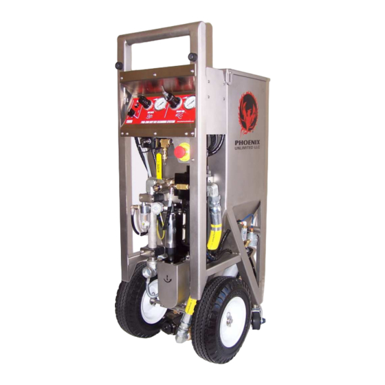
- Page 1 PHX-200 Dry Ice Cleaning System U S E R ’ S G U I D E...
-
Page 2: Table Of Contents
TABLE OF CONTENTS SYSTEM I.D. EQUIPMENT WARRANTY INTRODUCTION SAFETY PRECAUTIONS AND WARNINGS PHX-200 KEY COMPONENT IDENTIFICATION CONTROL PANEL/WARNING LABEL OPERATION INSTRUCTIONS Connecting the Air Supply Connecting the Blast Gun Pre-Start Up Checks Loading Dry Ice Applying Air to Unit Setting the Panel Controls... -
Page 3: System I
It may not be duplicated or disclosed to other parties. Inspected By: _______________________ Date: _______________________ ©2017 Phoenix Unlimited LLC. All rights reserved. Federal law provides severe civil and criminal penalties for the unauthorized reproduction or distribution of copyrighted material. -
Page 4: Equipment Warranty
Phoenix Unlimited LLC Equipment Warranty Phoenix Unlimited LLC (the Company) warrants that the Equipment it manufactures and delivers hereunder will be free of defects in material and workmanship for a period of twelve months or 2000 hours of operation from the date of shipment, whichever occurs first. -
Page 5: Introduction
Once you are comfortable with the information provided, you will be ready to say goodbye to old-fashioned methods of cleaning and begin using your new dry ice blaster. With proper equipment care, you will soon see that the PHX-200 is one tool you cannot be without. -
Page 6: Safety Precautions And Warnings
Emergency Stop Mechanism and other ways to stop blaster in Emergency The PHX-200 is equipped with a Mushroom Head Emergency Stop Button. Pushing this button will stop the unit immediately, requiring reset sequence to rearm the gun trigger. -
Page 7: High Velocity Particles
Ergonomics The training process for using your new PHX-200 is relatively easy, but there will still be a “learning curve” where technique and experience is concerned. The operator should understand that high velocity air exits the gun barrel. Upon triggering the gun, the operator will experience a small reactive thrust, which increases or decreases depending on pressure settings and air flow. -
Page 8: Phx-200 Key Component Identification
KEY COMPONENT IDENTIFICATION Control Panel System Supply Valve Auger Drive Lubricator Air Supply Inlet E-Stop Button Filter/Separator w/Autodrain Auger Drive Assembly Airlock Motor & Vibrator Lubricator Blast Hose Connections Vibrator Assembly Airlock Assembly... -
Page 9: Control Panel/Warning Label
CONTROL PANEL/WARNING LABEL ICE RATE BLAST AIR PHOENIX PHX-200 DRY ICE CLEANING SYSTEM UNLIMITED LLC www.phoenixunlimitedllc.com Read User's Guide Information ARM/DISARM Selector Asphyxiation Hazard ARM Indicator Wear Proper Protective Gear ICE RATE Regulator High Velocity Particles ICE RATE Gauge Burn Hazard... -
Page 10: Operation Instructions
CONNECTING THE AIR SUPPLY Since the PHX-200 is an “all pneumatic” design, it is critical that only clean, dry air be supplied to the unit. Air containing excess amounts of moisture, oil, rust, or other contaminants may clog filters and damage the logic control and internal components. -
Page 11: Connecting The Blast Gun
CONNECTING THE BLAST GUN 1. Use 1¼” and 1½” wrenches to connect the gun to the end of the blast hose with the shorter length trigger lines. Do not over-tighten. (pic 1) 2. Connect the respective trigger lines (different sizes) to the gun, pushing firmly into the quick- connect fittings. -
Page 12: Pre-Start Up Checks
PRE-START UP CHECKS CAUTION! Do not attempt to perform any maintenance or service on your PHX-200 unless safety guidelines and lock out/tag out procedures have been satisfactorily met! Before pressurizing the machine each day/shift, a quick preventive maintenance inspection should be performed to ensure that your unit operates problem-free now and in the future. -
Page 13: Loading Dry Ice
LOADING DRY ICE 1. Before you begin loading dry ice, it is important that you have the protective gear previously mentioned in the “Safety Precautions and Warnings” section (page 6). This includes basic items such as earplugs or muffs (or both), eye protection, face shield, heavy-duty gloves, long sleeves, long pants, and safety shoes. -
Page 14: Applying Air To Unit
3. Tighten jam nut to lock the blast air pressure. Note: The PHX-200 is factory set to purge air and ice 3 seconds at 45 PSI after trigger is released to clear the airlock and hose and prevent any clogging on the next trigger pull. -
Page 15: Arming/Disarming
Always Disarm when not blasting, especially when gun is unattended. WARNING: If trigger is engaged when arming, the unit will start blasting immediately! (NOTE: The PHX-200 will not arm if the E-STOP button is depressed, safety screen is removed, or trigger supply line is disconnected.) 1. -
Page 16: Stop Blasting
STOP BLASTING There are a few different ways to stop the blasting cycle. The PHX-200 reacts differently to each method. They are as follows: 1. Normal Stop: (pic 1) Under normal circumstances the way to stop blasting is to simply release the trigger. This will stop the auger and blast air. -
Page 17: Shut Down
SHUT DOWN 1. When blasting is complete, release the trigger and wait for airflow to stop. (There is a short delay while residual ice is purged at 45 PSI from the blast hose. Keep gun pointed at the target until air stops flowing! (Pic 1) 2. -
Page 18: Daily Preventive Maintenance
MAINTENANCE CAUTION! Do not attempt to perform any maintenance or service on your PHX-200 unless safety guidelines and lock out/tag out procedures have been satisfactorily met! DAILY PREVENTIVE MAINTENANCE Before pressurizing the machine each day/shift, a quick preventive maintenance inspection should be performed to ensure that your unit operates problem-free now and in the future. -
Page 19: Adding Oil
There are two lubricators on the PHX-200. One is for the Auger Motor located below the control panel, and the other is for the Airlock Motor and Hopper Vibrator located on the opposite side of the machine above the Blast Hose Connection. -
Page 20: Main Filter Inspection And Replacement
MAIN FILTER/SEPARATOR INSPECTION AND REPLACEMENT CAUTION! Do not attempt to perform any maintenance or service on your PHX-200 unless safety guidelines and lock out/tag out procedures have been satisfactorily met! To ensure that your dry ice cleaning system operates correctly and continues to provide reliable performance levels, the separator needs to be inspected regularly. -
Page 21: Trigger Line Filter And Blast Air Pilot Filter
Trigger Line Filter element. To perform this: 1. Locate the filter housing on inner leg of the PHX-200 near the airlock motor. (pic1) 2. Disconnect the tubing from filter housing push fittings (both ends), then remove filter housing from unit. -
Page 22: Periodic Maintenance
PERIODIC MAINTENANCE CAUTION! Do not attempt to perform any maintenance or service on your PHX-200 unless safety guidelines and lock out/tag out procedures have been satisfactorily met! AUGER DRIVE CHAIN Over time, the stainless steel drive chain may stretch; it is recommended that the drive chain tension be checked after every few months. - Page 23 Checking / Adjusting the Drive Chain Tension (cont.) 1. Use a 7/16” box wrench to loosen the adjustment screw retaining nut by turning counter- clockwise. (pic 7) 2. Hold the retaining nut in position and use a 3/16” hex key wrench to adjust the screw (clockwise to increase tension, counter-clockwise to relieve) until proper tension is achieved.
- Page 24 In order to properly inspect or replace the critical components, the airlock assembly must be removed from the unit. To do this: 1. Remove air supply hose from the PHX-200. Also remove the gun and blast hose assembly if attached. (pic 1) 2.
-
Page 25: Airlock
If all parts are good, install the new ASSY. BY rotor onto the spline. (pic 11) REVERSING 12. Reinstall airlock assembly onto the PHX-200 by STEPS 1-10 reversing steps 1-10. Pic 11 Airlock Motor / Spline: 13. - Page 26 Lubrication- Planetary gears, ball and needle bearings and seal ring should be lubricated with grease in conjunction with the regular overhaul of the motor. Molykote BR2 Plus gives long intervals between lubrications. Contact Phoenix Unlimited LLC or a qualified service center for motor overhaul options . 26...
- Page 27 6. 50114-158 ELBOW 7. 50004-002 ELBOW 8. 50053-001 VALVE 9. 50015-002 CONNECTOR 10. 50002-F04 PLUG 11. 50057-628 ELBOW FOLLOWING ITEMS NOT SHOWN 12. 10020-P12 BOLT (2) 13. 10018-005 LOCKWASHER (2) PHOENIX UNLIMITED LLC 30275-002A AIRLOCK MOTOR ASSEMBLY COMPLETE . 27...
-
Page 28: Factory Settings
FACTORY SETTINGS There are two factory set and locked regulators on the PHX. They are not readily accessible, so the chance of someone randomly changing their settings is low. However, if problems arise they should be checked. Many problems can stem from these regulators being out of adjustment. There is also a speed control valve that controls the duration of the purge delay. - Page 29 FACTORY SETTINGS (continued) Airlock Speed/Vibrator Stength/Purge Pilot Regulator This regulator controls the RPM of the Airlock Motor, the vibrating force of the vibrator and the Purge Air Pilot pressure to the Filter/Regulator. This setting is critical as these systems are balanced to run off the same pressure setting.
-
Page 30: Phx-200 Key Points
. 30... - Page 31 . 31...
-
Page 32: Troubleshooting
The PHX-200 can be function tested for short periods with a standard ¼” shop air hose. Do not run airlock dry for extended periods. You will need the following items to set it up. Fittings to connect shop air hose to the 1” inlet on the PHX-200. - Page 33 VB-3, VB-4) logic elements (L-4 L-5) to find where malfunctions. system is plugged or which device is malfunctioning. Clean out or replace tubing or device. Correct cause of contamination. TRIGGER DOES PHX-200 not ARMED Turn ARM selector clockwise, NOT START BLAST (indicator red) (indicator should turn green) CYCLE Trigger Lines improperly Check trigger lines at the machine and at the gun.
- Page 34 Reattach hose and remove nozzle from gun. Trigger again to clear ice from hose and gun. Reattach nozzle. Nozzle plugged with ice or Disarm PHX-200, Remove Nozzle and visually foreign material. inspect, remove blockage. Reinstall Nozzle. Be sure hopper lid is always closed to prevent any foreign material from entering blast system.
- Page 35 Test for Control Valve If no then the problem is in the Yellow tube Problem #2 manifold. Check for leaks, blockage or kinks. Does the control valve get a signal? If yes this will indicate a problem with the Control Valve CV-2, go to next test. Remove Yellow tube from Auger Control Valve CV-2.
- Page 36 ICE COMING OUT Is Nozzle Plugged? Pull Trigger, if no ice comes out check nozzle for AUGER TUBE ice plug and foreign objects {front of machine) Is Airlock being “over fed”? Reduce ICE RATE Pressure to 25 PSI. Too much ice will cause airlock to back up and ice to spill out front.
-
Page 37: Drawings
Rusty/Sticky vibrator Vibrator can be removed and cleaned with ATF fluid until the piston moves freely. VIBRATOR Check operation of the Vibrate Replace if it is malfunctioning VIBRATES ONE TIME “NOT” Valve L6. ONLY WHEN THE TRIGGER IS PULLED. VIBRATOR DOES NOT Is Vibrator Control Valve CV4 If no, it probably means the Control Valve is not VIBRATE AT ALL... - Page 38 VIBRATION DURATION VIBRATE TANK & ORIFICE "NOT" VALVE HOPPER VIBRATOR AT-2 VIBE1 RES-1 VIBRATOR CONTROL VALVE ARM "YES" VALVE PELLET SCREEN VALVE CV-4 CV-1 DISARM ARM CONTROL SELECTOR PI-1 VALVE VALVE VB-4 SYSTEM ARM INDICATOR (GREEN IS ARMED) VB-2 LATCH, AIRLOCK "OR"...
- Page 39 PHX-200 FLOW SCHEMATIC COMPONENT REFERENCE REFERENCE PART # DESCRIPTION FUNCTION AT-1 PURGE DELAY 50026-001 AT-2 VIBRATE DURATION AIR TANK 50026-002 AT-3 VIBE ON START 50026-001 CK-1 CHECK VALVE AUGER CONTROL 50113-025 CV-1 DISARM ISOLATION 50053-002 CV-2 AUGER MOTOR 50053-001 CV-3...
- Page 40 CONTROL PANEL CONTROL SHELF REG3 REG4 REG2 SEE FRAME MOUNTED COMPONENTS 30140-TUBEC DISTRIBUTION PHX-200 TUBE DIAGRAM SHEET 1 OF 4 AIR INLET DISTRIBUTION PG.40...
- Page 41 PG.41...
- Page 42 #26 TO AIRLOCK POPPET PILOT #25 TO SHUTTLE POPPET PILOT #40 FROM TRIGGER FILTER OUTLET #38 TO TRIGGER SUPPLY BULKHREAD FITTING #47 TO AUGER MOTOR POPPET VALVE PILOT #21 TO BALL VALVE ACTUATOR #10 FROM CONTROL REG #49 TO TIMING CYLINDER #51 FROM TIMING CYLINDER ELBOW PG.42...
- Page 43 CONTROL PANEL CONTROL SHELF CONTROL SHELF DISTRIBUTION HOPPER VIBE1 VIBRATOR LUBE1 LUBE2 FILTER TRIGGER SUPPLY AUGER DRIVE TRIGGER RETURN AIRLOCK 30140-TUBEC PHX-200 TUBE DIAGRAM SHEET 4 OF 4 FRAME MOUNTED COMPONENTS PG.43...
- Page 44 30060-001 FILTER/REGULATOR SERVICE INSTRUCTIONS 30061-001 BONNET PISTON UPPER 10031-001 PISTON SEAL LOWER PISTON SEAL MOUNTING SCREWS (4) TORQUE TO 13-18 INCH POUNDS 30062-001 FLANGE SLEEVE BE SURE THAT ALIGNMENT NOTCH AROUND SCREW HOLE IS PROPERLY ALIGNED POPPET ...
-
Page 45: Air System Assembly
FILTER/REGULATOR, PHX 50060-221 NIPPLE,1"NPT X close 50125-008 BALVE VALVE,VENTED,1"NPT 50106-462 ELBOW,FEMALE,1/8T X 1/4NPT 50067-002 FILTER,1/4" 50004-002 ELBOW,MALE,1/4NPT 30087-001 ELBOW,STREET,1"NPT,SP 50043-105 PIPE NIPPLE, 1" X 10.5 " 50009-016 ELBOW,1"NPT -001 AIR SYSTEM ASSY, PHX-200 PART NO. DESCRIPTION ITEM 30132 PARTS LIST PG.45... - Page 46 CONTROL PANEL ASSY ICE RATE BLAST AIR PHOENIX PHX-200 DRY ICE CLEANING SYSTEM UNLIMITED LLC www.phoenixunlimitedllc.com PG.46...
- Page 47 GAUGE, BLAST AIR, 300PSI 50104-001 REGULATOR, BLAST AIR 50109-005 SELECTOR, ARM/DISARM 50027-212 INDICATOR, SYSTEM ARM 50069-001 NUT, REGULATOR 50051-003 REGULATOR, ICE RATE 50108-060 GAUGE,ICE RATE,60 PSI 30125-001B CONTROL PANEL,PHX-200 -001 CONTROL PANEL ASSY PART NO. DESCRIPTION ITEM 30132 PARTS LIST PG.47...
- Page 48 DIN RAIL 10007-H04 SCREW,10-32 X 1/4" 30133-002 ARM DIST. BULKHEAD ASSY 50021-002 SPEED CONTROL 10019-015 FLATWASHER, 3/8" 50026-001 AIR RESERVIOR, 3.66 CI 30133-004 50016-002 ELBOW,5/32T X 1/8NPT VIBE ON START TANK ASSEMBLY -001 SHELF ASSY, PHX-200 -001 SHELF ASSY, PHX-200 PG.48...
-
Page 49: E-Stop Assy
PART NO. DESCRIPTION ITEM 30142 PARTS LIST REGULATOR ASSEMBLIES P/N 30134-001 P/N 30134-002 CONTROL AIR REG. PHX-200 AIRLOCK/VIBE/PURGE REG. PHX-200 1. 50094-001 REGULATOR 2. 50057-638 ELBOW 1. 50044-001 REGULATOR 3. 50096-002 ELBOW 2. 50057-628 ELBOW 4. 50122-003 TEE 3. 50114-143 ELBOW 5. -
Page 50: Auger Drive Assembly
30008-001 SUPPORT BLOCK 30007-001 CLAMP,SUPPORT BLOCK 10005-546 SCREW,FLT HD,1/4-20 X 1.75" 30088-001 RATCHET ASSY 50040-002 TEE, MALE RUN,1/4NPT 50016-002 ELBOW,5/32T X 1/8NPT 50002-Z04 PIPE PLUG,1/4" 50053-001 VALVE,POPPET,1/4" 50060-131 FLATWASHER, 3/8" 50126-002 LUBRICATOR 50057-628 ELBOW,3/8T X 1/4NPT -001 DRIVE ASSY,AUGER,PHX-200 PG.50... -
Page 51: Vibrator Assembly
VIBRATOR ASSY 50059-002 MUFFLER 50126-002 LUBRICATOR 50060-133 PIPE NIPPLE,1/4NPT X 2" 50057-628 ELBOW,3/8T X 1/4NPT 50040-002 TEE,MALE RUN,1/4NPT 50053-001 VALVE,POPPET,1/4" 50016-002 ELBOW,5/32T X 1/8NPT 50002-Z04 PIPE PLUG,1/4" 50060-131 PIPE NIPPLE, 1/4" CLOSE 50063-003 VIBRATOR,IMPACT -001 Vibrator Assy, PHX-200 PG.51... -
Page 52: Airlock Assembly
AIRLOCK ASSEMBLY PG.52... - Page 53 ELBOW, 1" 30278-001 CENTERING RING ADAPTER 30036-001 DISCHARGE TUBE, ICE/AIR 10020-K06 SCREW,SOC HD,10-24 X 3/8 10018-005 LOCKWASHER, 5/16 10020-P12 SCREW,SOC HD,5/16-18 X 3/4" 10020-N24 SCREW,SOC HD,1/4-20 X 1.5" 10025-B10 DOWELL PIN 10020-N12 SCREW,SOC HD,1/4-20 X 3/4 -001 AIRLOCK ASSY,PHX-200 PG.53...
-
Page 54: Auger Section
AUGER SECTION 2 REQ 2 REQ ITEM DESCRIPTION 20004-005 Bearing,Auger Output 30004-001 Auger,PHX 10012-029 Standoff/Bearing Retainer 10007-I06 Screw,1/4 x 3/8 10019-013 Flatwasher,1/4" 10018-004 Lock washer, 1/4" 30035-001 Sprocket,Auger 30090-001 Key,Auger 10032-812 Screw,Bearing Retainer 10006-240 Set Screw,Sprocket 30005-001 Bearing,Auger Input 10019-017 Flatwasher,1/2"... -
Page 55: Gun Assembly
GUN ASSEMBLY 6 REQ 3 REQ SECTION A-B 2 REQ SECTION A-A PG.55... - Page 56 30083-001C ITEM LIST ITEM DESCRIPTION 30091-001 THERMAL BREAK/ GASKET 50065-001 UNION, 5/32" TUBE 50065-003 UNION, 1/4" TUBE 10020-G12 SCREW, SOCKET HEAD, 6-32 X 3/4" LONG, SS 30057-001B HANDLE, GUN 50022-2BK 18" TUBING, POLYURETHANE, 5/32", BLACK 50070-4BK 18" TUBING, POLYURETHANE, 1/4", BLACK 10020-I20 SCREW, SOCKET HEAD, 8-32 X 1 1/4"...
-
Page 57: Specifications
SPECIFICATIONS Dimensions: 18” x 20” x 47” (W x L x H) (47cm x 51cm x 120cm) Dry Weight: 165 lbs. (74.84 kg) Hopper Capacity: Over 100 lbs. (45.5 kg) of pellets Ice Consumption Range: Adjustable rate .5 lbs. to 5 lbs./ min. (0.23 kg –... -
Page 58: Recommended Spare Parts List
RECOMMENDED SPARE PARTS Regular Maintenance (Class I) Part# Description Qty. 50067-00E Element Kit, Trigger Line/Blast Air Pilot 50067-001 Filter, Trigger Line 50067-002 Filter, Blast Air Pilot 50008-E01 Element Kit, Main Filter Repair (Class II) Part# Description Qty. 50126-ORG O-Ring, Lubricator Bowl 50053-001 Valve, Poppet, ¼”... -
Page 59: Customer Support
Customer Support (951) 278-2229 310 N. Cota Street, Suite H Corona, CA 92880 Telephone: (951) 278-2229 Fax: (951) 278-0084 http://www.phoenixunlimitedllc.com PG.59...
Need help?
Do you have a question about the PHX-200 and is the answer not in the manual?
Questions and answers