Table of Contents
Advertisement
Quick Links
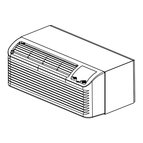
DC-INVERTER PACKAGED TERMINAL
AIR CONDITIONER/HEAT PUMP
INSTALLATION INSTRUCTIONS & OWNER'S MANUAL
ARAMA HEAT PUMP MODELS
DCIPT9
DCIPT12
DCIPT15
As a professional installer you have an obligation to know the product better than the customer. This includes all
safety precautions and related items.
Prior to actual installation, thoroughly familiarize yourself with this instruction manual. Pay special attention to all safety
warnings.
Often during installation or repair it is possible to place yourself in a position which is more hazardous than when the unit
is in operation.
Remember it is your responsibility to install the product safely and to know it well enough to be able to instruct a customer
in its safe use.
Safety is a matter of common sense, a matter of thinking before acting. Most dealers have a list of specific good safety
practices, follow them.
The precautions listed in this Installation Manual are intended as supplemental to existing practices. However, if there a
direct conflict between existing practices and the content of this manual, the precautions listed here take precedence.
ATTENTION INSTALLATION PROFESSIONAL
Advertisement
Table of Contents

Summary of Contents for ARAMA DCIPT9
- Page 1 DC-INVERTER PACKAGED TERMINAL AIR CONDITIONER/HEAT PUMP INSTALLATION INSTRUCTIONS & OWNER'S MANUAL ARAMA HEAT PUMP MODELS DCIPT9 DCIPT12 DCIPT15 ATTENTION INSTALLATION PROFESSIONAL As a professional installer you have an obligation to know the product better than the customer. This includes all safety precautions and related items.
-
Page 2: Table Of Contents
CONTENTS THE FOLLOWING WARNINGS VERY IMPORTANT FOR SAFETY. UNIT FEATURES……………………………………………2 PLEASE READ THEM CAREFULLY INSTALLATION INSTRUCTION……………………………4 I N S T A L L A T I O N ! B E F O R E WIRING…………………………………………………………7 )… … … 8 OPERATING INSTRUCTIONS( ACCESSORY OPTIONAL 1. -
Page 3: Unit Features
UNIT FEATURES This unit has many features which are different from those HEAT SPEED found on conventional PTAC units. The operator must be HIGH familiar with these features in order to properly handle the COOL unit . AUTO • DC-inverter compressor-Manufactured by ON/ OFF MITSHUBISH, due to its higher efficiency, energy saving up can be up to 30% to 80%. -
Page 4: Optional Accessories
J) Compressor starting fault WALL MOUNTED THERMOSTAT INTERFACE If compressor starting fails, 3 minutes later, it will try to start again. It will not display error code at the first 3 times fault. If the 4th time fail again, it will not start any more and R LS GH B Y W GL C display the error code. -
Page 5: Installation Instruction
INSTALLATION INSTRUCTIONS To ensure that the unit operates safely and efficiently, it must be installed, operated and maintained according to these installation and operating instructions and all local codes and ordinances or, in their absence, with the latest edition of the National Electric Code. The proper installation of this unit is described in the following sections. - Page 6 SLEEVE INSTALLATION MAIN STUD JACK STUDS HEADER-4"×4"OR 2-2"×4"ON EDGE Wall sleeve location When making the wall opening, please observe the following requirement: 16-1/4"MIN A) The air inlet and outlet should be unblocked and the air ADJUSTABLE FRAMING TO SECURE can be delivered to every corner of the room THIS DIMENSION 42-1/4"MIN B) Install the unit in places that are away from heat source...
- Page 7 OUTDOOR GRILLE 4. Secure the chassis to the wall sleeve using three screws (OPTIONAL ACCESSORY) on each side of the chassis to ensure a proper seal An outside grille must be installed to direct air flow for between the chassis and the wall sleeve. The screws are proper unit operation and also protect the outdoor coil.
-
Page 8: Wiring
VOLTAGE MEASUREMENTS WIRING Once the unit is properly wired, measure the unit supply 230~208V units are equipped with LCDI power cords and voltage. Voltage must fall within the voltage utilization can open the electrical circuit to the unit. In the event the range given in Chart 3 unit does not operate, check the reset button located on or... -
Page 9: Operating Instructions
OPERATING INSTRUCTIONS ( ACCESSORY OPTIONAL) Operation mode buttons Receiver of IR remote controller signal Fan Speed button Press these buttons to Press this button to select the select the unit operate on fan speed on high, low or heat mode, cool mode or fan auto. -
Page 10: Senior Operation
COOL/FAN/HEAT MODE OPERATION -9℃ to 9℃ If unit of temperature is changed, Indoor tempera- calibration should be done again. PROCEDURE If use the default value, it can be ture calibration -9℉ to 9℉ ignored. (default 0℃/0℉) Control panel: 1 indicates displaying room temp- Temperature dis- 0 or 1 erature, 0 for setting point... -
Page 11: Function Of Dip Switches
Step19: short press [-] key. VENTILATION CONTROL Display:'-1' (setting d4 has finished) The ventilation control lever is located at left side of unit, Setp20: short press [COOL] key. behind front panel. Display:'d4' NOTE: The vent door shipping tape must be removed before using vent control lever. -
Page 12: Maintenance And Cleaning
Discharge Air Flow WARNING 3. Remove the seven (7) screws which secure the HIGH VOLTAGE discharge air grille to the cabinet front. D I S C O N N E C T A L L P O W E R B E F O R E S E R V I C I N G O R INSTALLING THIS UNIT. - Page 13 2. Pull the filter straight up and remove. Routine scheduled Maintenance 3. Clean filter with vacuum or with running water. To achieve continuing top performance and high efficiency, establish a “once a year" cleaning/inspection schedule for Reverse this procedure to reinstall the filter the unit.
-
Page 14: Normal Operating Sounds And Condition
4. Tilt the non-compressor side of the unit up no higher NORMAL OPERATING SOUNDS than 45 degrees and allow water to drain out the other side AND CONDITIONS of the unit. 5. Remove excess water left in the base pan by wiping the Water trickling sounds base pan with a dry cloth. -
Page 15: Diagnostic Codes & Solutions
DIAGNOSTIC CODES & SOLUTIONS The Diagnostic Maintenance provides detailed information on PTAC control operation and operational status including present modes, failures , airflow restriction warnings , operating temperatures, and past failures Failure code Content of defect Solutions Check the communication cables, make sure they are Communication failure between firmly connected. -
Page 16: Troubleshooting
TROUBLESHOOTING POSSIBLE CAUSES SOLUTIONS ●Check that plug is plugged securely in wall receptacle. UNIT DOES NOT START ● Unit may have become unplugged Note :Plug has a test/reset button on it. Make sure that the ● Fuse may have blown plug has not tripped.
Need help?
Do you have a question about the DCIPT9 and is the answer not in the manual?
Questions and answers