Table of Contents
Advertisement
Quick Links
Advertisement
Table of Contents

Subscribe to Our Youtube Channel
Summary of Contents for Ampac Xpander Hub
- Page 1 Hub and Cluster Programming Manual MAN3090...
-
Page 2: Table Of Contents
Contents Introduction Radio Channels Currently Used System Overview RCC RCC Ch Device RCC Ch System Design Manual Select RCC RCC Ch Compatibility Device RCC Ch Auto Select Handling Precautions & Packing Individual Equipment Identification Advanced Equipment Familiarisation Change Address Device RCC Listing Quick System Programming Global Batt Stat Panel &... -
Page 3: Introduction
Introduction This manual provides a comprehensive guide to the programming of the Ampac Xpander Hub & Cluster System The Xpander System comprises of a Radio Hub capable of receiving information from a maximum of 31 Radio Cluster Communicators (RCCs). The RCCs are each capable of receiving information from up to 31 wireless devices. -
Page 4: System Design
XP95 optical, heat etc. Handling Precautions General: Care should be taken when handling the Ampac product range. Avoid dropping any of the parts onto hard surfaces, as damage may occur to the case and internal circuitry. -
Page 5: Equipment Identification
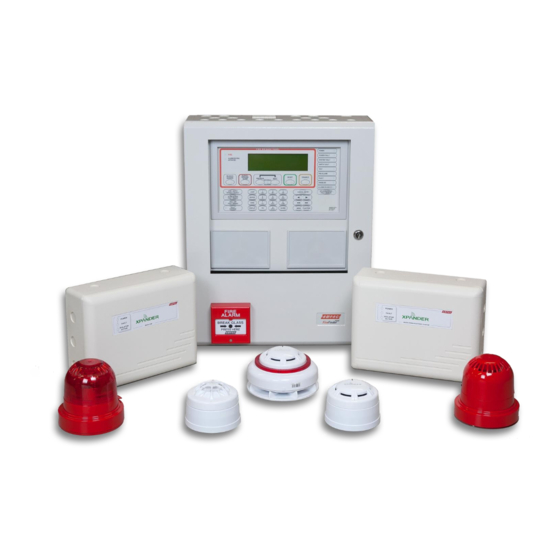
Equipment Identification It is important to establish which devices have been supplied for the installation. Examples of each device are shown below: Radio Cluster Wireless Input / Radio Hub Output Unit Communicator (RCC) 4110-2004 4110-2002 4110-2005 Wireless High Temp CS Wireless Optical Smoke Wireless Rate of Rise A1R Heat Detector... -
Page 6: Equipment Familiarisation
Equipment Familiarisation Wireless Call Point Log On & Alarm LED SIZE AA SIZE AA SIZE AA SIZE AA SIZE AA Ident Number Link both pins 1d872 to power device 10/10/14 Rev:1 Log On Button Power Jumper Wireless Detector Power Jumper Link both pins Log On Button &... - Page 7 Wireless Sounder Power Jumper Link both pins Log On Button & LED Ident Number to power device Wireless Sounder Base SIZE AA IDENT PRESS HERE TO 1d872 10/10/14 Rev:1 PRESS HERE TO LOG ON LOG ON Wireless Input / Output Unit Log On Button Ident Number LOGON...
-
Page 8: Quick System Programming
Quick System Programming This quick system programming guide provides a recommended procedure into the installation and programming of the Xpander Radio System. Before commencing with the installation, the survey report should be available detailing where the control panel and wireless infrastructure is to be fitted. Ensure the correct equipment is to be fitted at the designated location, see Equipment Familiarisation section. -
Page 9: Assign Rccs
Assigning RCCs The newly added RCCs should now be assigned. From Unassigned Dev Assign Device Assign RCCs Dev 000 of 001 changing to Done 001 of 001 (once complete). To Exit BACK Device Installation & Programming Wireless devices can be programmed to their relevant RCC prior to their installation. The devices must be powered up and then added to their relevant RCCs, by pressing their log on buttons. -
Page 10: Equipment Features
Equipment Features The Controls and Indications section details the various features of the Radio Hub, Radio Cluster Communicator and wireless devices. Radio Hub The Radio Hub has 3 visible LED indicators from the front of the housing and also internal LED indicators, controls, display and connectors. - Page 11 Internal Indications RF1 RX LED; a green LED will flash when data is received from a Radio Cluster Communicator, using receiver 1. RF2 RX LED; a green LED will flash when data is received from a Radio Cluster Communicator, using receiver 2.
-
Page 12: Rcc
The Radio Cluster Communicator (RCC) has 2 visible LED indicators from the front of the housing and also internal LED indicators, controls, display and connectors. This section explains their functionality. HEALTHY FAULT SYS FAULT RESET BACK LOGON MAN3090-1 Page 12 of 38... - Page 13 Reset Button; the reset button is used to reset the Radio Cluster Communicator. Back Button; the back button is not used on the Radio Cluster Communicator. Log On Button; the log on button is used to log the Radio Cluster Communicator on to the Radio Hub. ENG 1 Port;...
-
Page 14: Wireless Devices
Wireless Devices The wireless devices have LED indicators and log on buttons which perform certain functions. This section explains their functionality. Log On Button; the Log On button is used for adding devices to the system. The required procedure for achieving this is detailed within the ‘Quick System Programming’... -
Page 15: Menu Structure
Menu Structure Alarm Status shown as I/O Status for Input/Output device types. Programming features not yet released in this version of software. † MAN3090-1 Page 15 of 38... -
Page 16: Front Display
Front Display Once the Control Panel and the Radio Hub are installed and powered up, the Radio Hub will show the following default screen: TOT001 A000 F000 Where: TOT001 = The Total number of devices logged to the Hub (including the Radio Hub itself ) across all 4 possible loop options. -
Page 17: Menu Explanation
Menu Explanation Device Status The device status menu lists all of the devices assigned to all the loops. Devices can be scrolled through using the rotary controller. The allocated loop and address numbers are shown, along with the device type and its current status. The devices are displayed in Loop and Address number order. Front Display Device Status A typical display is shown below;... -
Page 18: Fault Status
Fault Status; Upon entry, this shows the devices fault condition information. To view the actual fault for a particular device, the rotary control can be pushed to display a fault description. If a device has multiple faults, they can be individually viewed by turning the rotary control. Front Display Device Status Select Desired Device No... -
Page 19: Alarm Status
Alarm Status; when entered, this shows the devices alarm condition information. To view the actual alarm for a particular device, the rotary control can be pushed to select the device and this will then display the alarm description. Front Display Device Status Select Desired Device No Alarm... -
Page 20: Battery Level
Battery Level; this menu when entered shows information on the selected device’s battery status. The status of the pack is updated whenever there is a status change or automatically updated every 6 hours. This is broken down into five sections. Front Display Device Status Select Desired Device No... -
Page 21: Signal Level
Signal Level; this menu allows the signal levels for devices to be viewed. When entered detailed signaling information is displayed on the two signaling channels used by the device in both directions, as the devices are bi-directional. The received signal strength at the devices associated RCC is shown as a D RCC01 level, therefore indicating the signal that has been sent from the device to the RCC (the 01 represents the RCC number). -
Page 22: Rcc Number & Ident
RCC Number & Ident; this displays the RCC number that the selected device is currently assigned to along with the devices ident. You can also change the RCC that the device is logged onto by pressing the Rotary Control when the RCC number is displayed and then selecting a new RCC from the available list. Front Display Device Status Select Desired Device No... -
Page 23: Hub/Rcc Options
Hub/RCC Options This menu allows access to the configuration of the Radio Hub and Radio Cluster Communicators. Front Display Hub/RCC Options Set Hub Address; this section allows the Radio Hub to be allocated to a particular loop and Loop Address number. -
Page 24: Hub/Rcc Status
Hub/RCC Status; when entered, this menu lists the Radio Hub and all of the Radio Cluster Communicators added to the system. These can be scrolled through using the rotary controller. The allocated loop and address numbers are shown along with their current status. Front Display Hub/RCC Options Hub/RCC Status... -
Page 25: Fault Status
Fault Status; this menu when entered shows information on any Radio Hub or Radio Cluster Communicator that are currently in a fault condition. To view the actual fault for a particular unit, the rotary control can be rotated and pushed to select the relevant address and this will then display a fault description. -
Page 26: Signal Level
Signal Level; this menu allows the signal levels for selected Radio Cluster Communicator to be viewed. When entered detailed signalling information is displayed on the two signalling channels used by the RCC in both directions, as the devices are bi-directional. The received signal strength at the Hub from the associated RCC is shown as a R01 Hub level, therefore indicating the signal that has been sent from the RCC to the Hub (the 01 represents the RCC number). -
Page 27: Manual Update
Manual Update; this menu allows individual RCCs to update the system with their current signal levels. To send a signal request, press the rotary control button with the relevant RCC shown on the display. The menu will change to show ‘Update Requested’. Once completed, check the new signal level by entering the Signal Level menu. -
Page 28: Radio Channels
Radio Channels This menu allows you to view or alter the frequency channels currently used by the system. NOTE: Alterations to the Radio Hub and RCC communication channels can only be undertaken when no RCCs are allocated to the system. Alterations to the RCC and Device communication channels can only be undertaken when no devices are allocated to that particular RCC. - Page 29 Multiple RCC Channel Allocation Example The example below shows a multiple RCC installation using different frequency channels. The channels used in the example are colour coded and also shown in the table below. Having a system setup in this way ensures the two device channels used for each RCC are taken from the low and from the high band and are not duplicated.
-
Page 30: Currently Used
Currently Used Once entered, currently used channels for ‘RCC RCC Ch’ and ‘Device RCC Ch’ will be accessible. RCC Ch; channels being used for the RCC to RCC communication can be viewed by selecting the following: Front Display Radio Channels Currently Used RCC Ch Device RCC Ch;... -
Page 31: Auto Select
Auto Select Once entered, options for ‘Individual’ and ‘All’ automatic channel selections will be available. Individual; individual Device to RCC communication channels can only be automatically selected whilst no devices are added to the RCC. This option will allow a scanning time to be selected between 1-60 mins. In this time the frequency channels will be scanned and at the end of the timer, the two best channels for use will be selected: Front Display... -
Page 32: Global Batt Stat
Global Batt Stat; this menu allows the wireless devices battery statuses to be viewed. The devices are listed in loop and address order. Each device will show the status of its two battery packs. The battery status information is displayed as follows;... -
Page 33: Start Fast Test
Start Fast Test; in this menu, loops can be entered into fast test for ease of testing. This allows the detectors on the selected loops to be triggered into an alarm condition quicker than normal. The led on the device will flash to indicate it is in this fast test mode. A time period of between 1 and 30 minutes is selectable which decrements and is then re-generated on a fire alarm event. -
Page 34: Call In Verify
Call in verify; this menu allows access via a password to select between EN and Non-EN modes of system operation for fault monitoring of device communication loss. In EN mode a fault due to the loss of communication with a wireless linked component is indicated at the control and indicating equipment within 300 seconds of occurrence of the fault. -
Page 35: Analogue Values / Fault Rectification
Analogue Values / Fault Rectification Analogue Device Symptom Rectification Value Type Process Battery missing Check battery connections and voltages. Ensure all batteries are changed if required. Mains fail Check the RCCs mains supply. Detector Head fault Check that the device is correctly assembled. Failing this, it is recommended that the detector is replaced. -
Page 36: Signal Level Requirements
Signal Level Requirements To ensure the signal levels for each wireless device and each RCC are at an acceptable level the Global Sig Stat menu should be checked. This menu will display the signal levels in dB for each wireless device and RCC over a 24 hour period. - Page 37 An example of a display showing the levels for a system which does not have the required signal levels is shown below: Device Type Loop / Address Shown On Display Acceptable Level Radio Hub Loop 1 Address 1 Loop 1 Address 2 L1 A002 19dB Optical Detector Loop 1 Address 3...
-
Page 38: How To Improve Signal Levels
How to Improve Signal Levels Device signal levels can be improved by following the flowchart below: MAN3090-1 Page 38 of 38...
Need help?
Do you have a question about the Xpander Hub and is the answer not in the manual?
Questions and answers