Table of Contents
Advertisement
Quick Links
Advertisement
Table of Contents

Summary of Contents for Haefely Technology AXOS5
- Page 2 A Note to Begin Thank you for choosing the Haefely AXOS . Please take a little time to read through this user manual and familiarize yourself with the instrument controls and some potential dangers. We hope you have many productive years of operation from the AXOS Compact Immunity Test System .
-
Page 3: Table Of Contents
Contents CONTENTS ........................I SAFETY.......................1 General Safety Information................1 Safety Standards .....................1 PRODUCT DESCRIPTION ..................2 Basic information ....................2 Standards covered by AXOS ................3 TECHNICAL DATA ....................4 General ......................4 Surge ......................4 Burst .......................4 Voltage dips ....................5 Integrated single-phase CDN ................5 INITIAL OPERATION ..................6 Visual check ....................6 Installation .....................6 Earth connection .....................6... - Page 4 SURGE ......................13 General information..................13 Combination wave generator ................ 13 6.2.1 Open Circuit Voltage (OCV) ................13 6.2.2 Short Circuit Current (SCC) ................14 SURGE Menu ....................14 6.3.1 Output & Coupling Paths .................16 6.3.2 Properties .....................16 6.3.3 Transition .....................17 6.3.4 Trigger ......................17 6.3.5 Synchronization AC ..................18...
- Page 5 Electrical fast transient/Burst ............... 35 12.1.4 Burst verification adapter ................35 12.2 Calibration.....................35 12.3 Recycling.......................36 ACCESSORIES AND OPTIONS ................37 13.1 AXOS5 Accessories..................37 ADDITIONS ......................38 14.1 Addresses......................38 14.1.1 International customer service ..............38 14.1.2 USA customer service ................. 38 14.1.3 China customer service ................38 14.1.4...
-
Page 7: Safety
1 Safety 1.1 General Safety Information Significant: Please read carefully the safety requirements before using the AXOS This warning sign is visible on the equipment. Meaning: The documentation must be consulted before connecting the equipment to any voltage supply Dangerous mains voltage or high voltages are present inside the AXOS The earth connection of the AXOS must be connected to a good earth. -
Page 8: Product Description
2 Product description 2.1 Basic information The AXOS compact immunity test system integrates all of the best pieces of our stand alone test systems into one single economic solution. It combines 5 kV Burst/EFT, Surge combination wave, AC/DC Dips & Interrupts, along with an integrated single-phase coupling / decoupling network into one compact system. -
Page 9: Standards Covered By Axos 5
2.2 Standards covered by AXOS Table 2-1 Basic standards covered by the AXOS Standard Description Test equipment IEC/EN 61000-4-4 EST/Burst AXOS IEC/EN 61000-4-5 Surge AXOS IEC/EN 61000-4-9 Magnetic field AXOS & MSURGE-A IEC/EN 61000-4-11 AC Voltage Dip and Interrupt AXOS &... -
Page 10: Technical Data
3 Technical data 3.1 General General Data Control Power 85V - 264V Dimensions 19" / 4U 50/60 Hz (W x H x D) (45 x 18 x 49 cm) User Test Storage Unlimited Weight 30kg Remote Interface Ethernet for USB memory stick RJ45 Display 7"... -
Page 11: Voltage Dips
3.4 Voltage dips IEC / EN 61000-4-11 Edition 2 and IEC / EN 61000-4-29 Dips & Interrupts Max. Voltage 264V AC/DC Interrupt Time 0.5 period – 800 periods 100us – 1000 minutes Max. Current 16A AC/DC continuous Interval Time 1 period – 800 periods 20A for 5s synch 40A for 3s... -
Page 12: Initial Operation
4 Initial operation 4.1 Visual check During transport AXOS may be subjected to excessive shocks and vibrations, even though every care is taken by HAEFELY Test AG to provide suitable packaging. Before operating the unit, check for signs of mechanical damage. Damaged packing cases may by a sign of transport damage. -
Page 13: Connection To Eut
Inside the AXOS, there are filter capacitors connected between L-PE and N-PE, as required by the standard. These capacitors will cause a residual current, which will trip the residual current circuit breaker. Hence, an isolation transformer needs to be inserted between main power supply and "EUT Supply Input" as shown in Figure 4-1 below. -
Page 14: General Operation
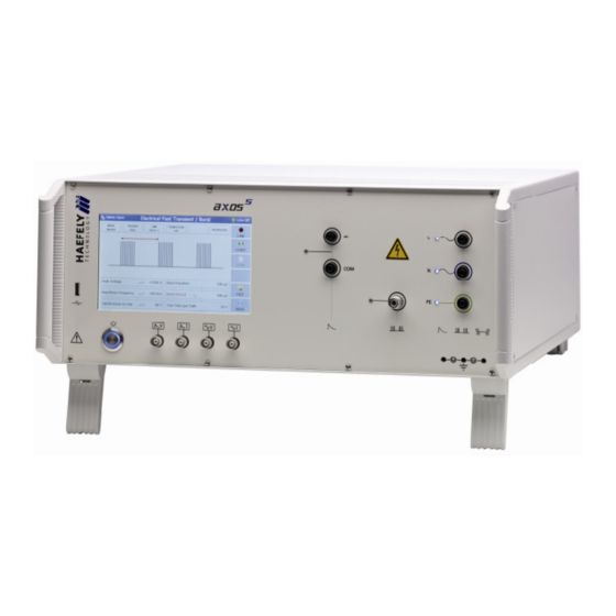
5 General operation 5.1 Front view The Figure 5-1 shows the front view of the AXOS . In the Table 5-1 is the detail description of every physical input and output. Figure 5-1: AXOS Front view Pos. Function Description On/off switch Turns on and off the power of AXOS Surge impulse voltage 1000:1 divider for surge impulse. -
Page 15: Rear View
Sync. BNC Interface The BNC interface is used for external synchronization of a manual CDN Main power switch for AXOS5 Switching on/off total power supply Electrical grounding The generator must always be connected to a reference earth... -
Page 16: Setup Menu
AUX (Pos. 7.) function description Red warning lamp Indicates when safety circuit closed Green warning lamp Indicates when safety circuit opened Safety interlock When safety barriers installed, connection must be done between pin 5 and pin 4 to close the circle (safety instruments), however, bridge between pin 4 and pin 5 exist as delivery setting Start/Stop program 1 is running (Input) -
Page 17: Predefined Standard Program
Remote GUI Remote GUI is possible to access when license key purchased from the HAEFELY TEST AG; switch on/off of communication between remote computer and AXOS5 possible Coil Antenna Entering of new “coil Antenna” factor as described in... -
Page 18: Icon Bar
However, through the “Setup” menu predefined programs can be loaded and applied via an external “start/stop” device. There get controlled though Pin 7 in Table 5-3. When particular file has been selected, it must be confirmed with “load”. Figure 5-5: File selection Internal/Standard Note: When file wants to be applied and started without any external signal parameter, it must be selected inside the specific modus (e.g. -
Page 19: Surge
Please read carefully the Table 5-1 and Table 5-2 in detail before first use of the Surge generator. The short voltage impulse stays on the EUT during several µs. The peak voltage gets with the Axos5 up to 5 kV. The generator fulfils the requirements according to the IEC 61000-4-5 norm. -
Page 20: Short Circuit Current (Scc)
6.2.2 Short Circuit Current (SCC) Figure 6-2: Short circuit current (SCC) [1] Front time: T1 = 1,25 x T = 8 µs ± 20% Time to half value: T2 = 20 µs ± 20% For verification of the output signal, a current transformer must be connected between position 6 and position 7 as shown in Figure 5-1. - Page 21 In the Figure 6-4 it shows the use of the pre-compliance mode. Indeed, every parameter can be changed by simply pressing on the black bows next to the value. Furthermore, it can be changed between direct and line output. All data entries can be done while the generator is operating.
-
Page 22: Output & Coupling Paths
The safety symbol, the direct output and the output voltage and output current are displayed. In addition, the user is able to see nominal values of the peak voltage, reputation time and the synchronization period. Additionally, these values can be modified while the test is proceeding. It happens by simply pressing each particular function. The test stops when pushing the “STOP”... -
Page 23: Transition
Position Description External (Pin11 on Aux) External condition (e.g. device or PLC signal), the position becomes 1 and causes an action (Ignore, Alarm, Test Stop or test stop & line off) Line Current Limits the current (L, N, PE front view) to the EUT. Peak voltage It defines an area (min. -
Page 24: Synchronization Ac
6.3.5 Synchronization AC To synchronize the surge signal with the main supply source it is necessary to adjust in the menu “Synchronization” and then “Line Sync.”. Further adjustments of the angle can be done in a range from 0° to 359° . However, if no power supply is connected to the EUT input at the rear view, it has to be entered “Async.”, otherwise it is impossible to get a Surge impulse of the generator. -
Page 25: Magnetic Field
7 Magnetic field 7.1 General Information The test setup is described in accordance to the norm IEC 61000-4-9. A SCC waveform will be created. For the magnetic field the coil gets connected directly via banana plug to the surge output HI and COM as written in position 6 and Position 7 in Figure 5-1. -
Page 26: Coil Antenna
“Rep.Data”. However, first connect device to USB port. 7.1.1 Coil antenna When the AXOS5 has started, the setup menu contains a standard predefined coil in accordance to IEC 61000-4-9. It can be up to 10 different coil factors added to the menu. -
Page 27: Transition
7.1.2 Transition In “Transition” (Figure 7-5) the user can adjust the “Field Strength”, “Sync. Phase” and “Alternative Polarity”. The description from capture 6.3.3 is valid, except “peak voltage” has been changed to “field strength”. The other parameters stay equal, since an OCC will be applied to the coil antenna and is basically a Surge impulse. Figure 7-5: Magnetic field transition When all parameters has been entered then simply confirming with ok and in the menu is showing “transition on”, this indicates the settings will be applied to the coil antenna when pushing the “start”... -
Page 28: Electrical Fast Transient Burst
8 Electrical Fast Transient Burst 8.1 General information The Burst generator generates Electrical Fast Transient Bursts (EFT) as described in IEC 61000-4-4. The source impedance of the generator is 50 . The burst is a common mode transient, coupled simultaneously to all selected paths with respect to ground. -
Page 29: Output & Coupling Paths
The following graphic represents the pre-compliance mode. In comparison with the standard menu, every command gets displayed the entire visual description of the function is described through purple bows. Main advantage of the pre-compliance mode is that the parameter can be changed while the test is operating. Figure 8-3: EFT / BURST pre-compliance mode However, when every parameter has been adjusted, the “Start”... -
Page 30: Properties
Limits the current (L, N, PE front view) to the EUT Action: Ignore, Alarm, Test stop, Test stop & line off Due to EUT fails, AXOS5 cause an action which can be: Ignore, Alarm, Test Stop, Test Stop & Line off. -
Page 31: Trigger
8.2.4 Trigger When selecting “manual trigger” the following window opens up. It gets applied to EUT by pressing the “Trigger” button. It gets always only one Burst package applied. Figure 8-7: BURST mode Trigger normal Furthermore, it shows between which line and GND the burst package gets applied. After finalizing the process, it will be stopped when pushing the “Stop”... -
Page 32: Voltage Dips & Interrupts
9 Voltage dips & interrupts 9.1 General information For the voltage dips & interrupts only the EUT will be only connected through the output (L, N, PE) in the front view. The EUT Supply Input (L, N, PE) in the rear view gets connected to the power supply. For verification of the signal, Pos.4 and Pos.5 in Figure 5-1 can be connected to the oscilloscope. - Page 33 when using the D116 transformer. The selection happens in the “Dip Voltage” menu field. When selecting 0% it creates a voltage interrupt, since the V dip becomes 0V. The Figure 9-3 shows the voltage dips in standard mode. When pushing the particular function name: “Dip Voltage”, “Line sync.”, “Duration”, “interval”...
-
Page 34: Transformer Dip 116
The HAEFELY TEST AG DIP 116 transformer will be connected through the V Dip and the Link input at the rear view of the AXOS5. The DIP 116 has an independent connection to an external power supply via banana plug. Once the... -
Page 35: External Transformer
9.3.2 External transformer The only connection from the external transformer (Figure 9-6) with the compact immunity tester happens through V dip and N’ at the rear view via banana plug. L and N from the external transformer gets connected to the power supply. The output voltage (between V dip and N) gets displayed as adjusted at the transformer. -
Page 36: Transition
9.3.4 Transition The Figure 9-7 shows the “transition” menu. It is possible to select independently “Duration”, “Interval”, “Phase” and “Alternate polarity”. To be able to select “phase” the Synchrony has to be either set as Synchronization or external Synchronization, otherwise it is not possible to access it. Eventually, every parameter can be changed by pushing the certain value. -
Page 37: Error Messages
Start File EUT requires more than 16 A support -check Inominal of EUT (max. current, may EUT defect, short circuit EUT support with AXOS5 16A) -control EUT independently, short circuit might occurred, -External CDN necessary, if EUT requires more than 16 A support... -
Page 38: Logic Errors
10.3 Logic errors Alarm message Possible cause Action needed Decrease peak voltage / rep. Too many spikes per second frequency / Burst or increase burst period Decrease peak voltage , Repetition frequency is too high repetition frequency Decrease burst duration / Sync. burst period / burst duration incompatible time Decrease burst duration /Sync. -
Page 39: Software
11 Software 11.1 Remote Software A remote software for the AXOS is available. Connection through RJ45 input at the rear view. If further assistance required, please contact either your HAEFELY TEST AG representative or the sales department of the HAEFELY TEST AG. -
Page 40: Service
12 Service 12.1 Verification In the next under captures are descriptions of our additional verification equipment for the AXOS . If further information required of any of the equipment, please either contact your sales representatives or the HAEFELY TEST AG technical support team directly. -
Page 41: Electrical Fast Transient/Burst
12.1.3 Electrical fast transient/Burst The HAEFELY EFT Verification Kit includes a 50 and 1000 attenuator as required in the IEC 61000-4-4 standard. The appropriate attenuator is fitted to the “Burst” coaxial output, and an oscilloscope is then connected to the output of the attenuator. -
Page 42: Recycling
12.3 Recycling When the instrument reaches the end of its working life it can, if required, be disassembled and recycled. No special instructions are necessary for dismantling. The instrument is constructed of metal parts (mostly aluminium) and synthetic materials. The various component parts can be separated and recycled, or disposed of in accordance with the associated local rules and regulations. -
Page 43: Accessories And Options
CP 101 Current Probe Model for Surge 2499931 ES External emergency stop Switch P12 4700751 WL External warning Lamp P12 4700750 WinFEAT'R Control, Measurement & Reporting Software 2499701 Calibration Accredited Calibration AXOS 2490420 Table 13-1: Article for AXOS5 AXOS Compact immunity test System... -
Page 44: Additions
14 Additions 14.1 Addresses 14.1.1 International customer service e-Mail: EMC-Support@haefely.com Address: Haefely Test AG Birsstrasse 300 4052 Basel / Switzerland Fax : + 41.61.373 45 99 Internet: www.haefelyEMC.com 14.1.2 USA customer service e-Mail: EMC-Support@haefely.com Address: Hipotronics Inc. Department EMC 1650 Route 22 Brewster, NY 10509 / USA Telephone : (845) 279 3644 Fax :... -
Page 45: Glossary Of Terms And Abbreviations
14.2 Glossary of terms and abbreviations meaning: Helpful hints, notes, tips or remarks meaning: Attention! Equipment Under Test Coupling Decoupling Network High Voltage Light Emitting Diode International Electro-technical Committee European Norm ANSI American National Standards Institute Electro Magnetic Compatibility German equivalent of EMC Decoupling network Coupling / Decoupling module (Electrical circuit for transferring energy between networks with the minimum loss and that attenuates the Surge signal so that it does not cause undue... -
Page 46: Reference
14.3 Reference • [1] IEC 61000-4-5 Testing and measurement techniques-Surge immunity test, part 4-5, edt.2, 2005/11 • [2] IEC 61000-4-4 Testing and measurement techniques – Electrical fast transient/burst immunity test, part 4-4, edt.2, 2004/07 • [3] IEC 61000-4-11 Testing and measurement techniques-voltage dips, short interruptions and voltage variations immunity tests, part 4-11, edt. -
Page 47: Table Of Figure
14.4 Table of figure Figure 1-1: Safety sign ..............................1 Figure 2-1: Start display ..............................2 Figure 4-1: Transformer connection ..........................7 Figure 5-1: AXOS Front view ............................8 Figure 5-2: AXOS rear view ............................9 Figure 5-3: Setup menu..............................10 Figure 5-4: Save and load option of data ........................ -
Page 48: Table Of Table
Table 8-1: BURST properties description........................24 Table 9-1: Properties Voltage Dips & Interrupts ......................29 Table 10-1: Error messages ............................31 Table 10-2: Logic causes and actions..........................32 Table 13-1: Article for AXOS5 ............................37 AXOS Compact immunity test System... -
Page 49: Appendix
15 Appendix 15.1 CE conformity AXOS Compact immunity test System...
Need help?
Do you have a question about the AXOS5 and is the answer not in the manual?
Questions and answers