Table of Contents
Advertisement
Advertisement
Table of Contents

Summary of Contents for Longjia LJ1P37QMB(3B3)
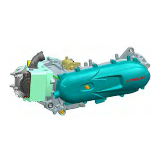
- Page 1 LJ1P37QMB(3B3) 4- STROKE 50cc SERVICE MANUAL...
-
Page 2: Table Of Contents
CONTENTS CONTENTS SPECIFICATION/TIGHTEN TORQUE VALVE MAINTENANCE INFORMATION LUBRICATION SYSTEM ELECTRONICALLY CONTROLLED CARBURETOR SYSTEM REMOVAL ENGINE CYLINDER HEAD & VALVE CYLINDER & PISTON V BELT DRIVING SYSTEM / KICK START SYSTEM FINAL DRIVING SYSTEM CRNKCASE & CRANKSHAFT STARTING CLUTCH... - Page 3 1. SPECIFICATION / TIGHTEN TORQUE VALUES SPECIFICATIONS ......1-1 TORQUE VALUES (ENGINE) ....1-2 SPECIFICATIONS MAKER LONGJIA MODEL Transistorized coil Type 4-STROKE ENGINE Ignition ignition Installation and Vertical, below center, Starting System Electrical & Kick starter arrangement incline 80° Fuel Used...
- Page 4 1. SPECIFICATION / TIGHTEN TORQUE VALUES TORQUE VALUES (ENGINE) THREAD DIA TORQUE ITEM Q'TY REMARKS (mm) VALUE(N.m) Cylinder head bolts 8~12 Cylinder head left side cover bolts 8~12 Cylinder head nuts 12~16 Apply oil to thread Cylinder/cylinder head two-ends bolts 7~11 Tighten to crankcase Tappet adjust hole cap...
-
Page 5: Maintenance Information
2. MAINTENANCE INFORMATION PRECAUTIONS IN OPERATION ..2-1 CARBURETOR IDLING SPEED PERIODICAL MAINTENANCE ADJUSTMENT ........2-5 SCHEDULE ........2-2 IGNITION SYSTEM/SPARK PLUG .. 2-6 LUBRICATION SYSTEM ....2-3 CYLINDER COMPRESSION AIR CLEANER ........2-4 PRESSURE ........2-7 VALVE CLEARANCE INSPECTION & DRIVING SYSTEM ...... - Page 6 1. These marks “☆” in the schedule are emission control items. According to EEC regulations, these items must be perform normally periodical maintenance following the use r manual instructions. They are prohibited to be adjusted or repaired by unauthorized people. Otherwise, LONGJIA is no responsible for the charge.
-
Page 7: Lubrication System
2. MAINTENANCE INFORMATION LUBRICATION SYSTEM Engine Oil Capacity Caution Ÿ The vehicle must be parked on a level ground when checking oil capacity. Ÿ Run the engine for 2-3 minutes then stop, wait about 2-3 more minutes allowing engine oil to settle before checking the oil level. - Page 8 2. MAINTENANCE INFORMATION Gear Oil Gear oil refilling bolt Inspection Check gear oil if leaking. Park the motorcycle with main stand on flat level place. Turn off engine and remove the gear oil draining plug. Place a measurement cup under the draining hole.
- Page 9 2. MAINTENANCE INFORMATION VALVE CLEARANCE ADJUSTMENT Air cleaner element Caution Checks and adjustment must be performed when engine is cold (below 35℃). Remove luggage box and front center cover. Remove the left body cover & left side cover. Remove cylinder head cap. Remove the ignition timing check hole on the cooling fan cover.
- Page 10 2. MAINTENANCE INFORMATION Park the motorcycle with main stand and warn up engine. Open the carburetor cover from the luggage box. Turn the throttle valve stopper screw to specified idle speed. Specified idle speed: 1900±100 rpm Emission adjustment in Idle speed Warm up the engine for around 10 minutes and then conduct this adjustment.
- Page 11 2. MAINTENANCE INFORMATION CYLINDER COPMRESSION PRESSURE Warn up engine and then turnoff the engine. Remove the luggage box and the center Cover. Remove spark plug cap and spark plug. Install compression gauge. Full open the throttle valve, and rotate the engine by means of stepping the kick-starting lever.
- Page 12 2. MAINTENANCE INFORMATION Crankcase blow-by over-flow pipe Replacement for every 1000km 1.Open the stopper 2.Drain the oil 3.Install the stopper Remove dipstick to check the oil level. If oil level is below the lower limit mark, add oil to the specified upper limit mark.
- Page 13 3. LUBRICATION SYSTEM OIL FLOW DIAGRAM ......3-1 CLEANING ENGINE OIL STRAINER ... 3-3 GENERAL INFORMATION ....3-2 OIL PUMP ..........3-4 TROUBLESHOOTING ....... 3-2 GEAR OIL ..........3-6 ENGINE OIL ........3-3 OIL FLOW DIAGRAM Valve rocker Forcedly lubrication Camshaft Scoop lubrication Inner passage...
- Page 14 3. LUBRICATION SYSTEM GENERAL INFORMATION This chapter contains maintenance operations for the engine oil pump, engine oil and gear oil. Oil viscosity Specifications Engine oil quantity Disassembly 800 c.c. Replacement 700 c.c. Oil viscosity SAE 15W-40 or equivalent Use SAE 5W-40 when outside temperature is below 0℃.
- Page 15 3. LUBRICATION SYSTEM ENGINE OIL Turn off engine, and park the motorcycle in flat ground with main stand. Check oil level with oil dipstick after 3-5 minutes. Do not rotate the dipstick into engine as checking. If oil level is nearly low level, fill out recommended oil to upper level.
- Page 16 3. LUBRICATION SYSTEM OIL PUMP Oil Pump Removal Remove the alternator (refer to chapter12). Remove the engine right crankcase cover. Make sure that the pump axle can be rotated freely. Remove the oil pump driving gear nut. Remove the oil pump . Oil Pump Inspection Check the clearance between oil pump body and outer rotor.
- Page 17 3. LUBRICATION SYSTEM Check clearance between rotor side face and pump body. Limit: below 2.0 mm Oil Pump Re-assembly Fixing pin Oil pump body Drive shaft Install inner and outer rotors into the pump body. Align the indent on driving shaft with that of inner rotor.
- Page 18 3. LUBRICATION SYSTEM GEAR OIL Gear oil draining plug Oil Level Inspection Park the motorcycle on flat ground with main stand. Turn off engine and remove both gear oil filling bolt and gear oil draining plug. Remove gear oil filling bolt and place a measurement cup under the draining plug.
-
Page 19: Electronically Controlled Carburetor System
. ELECTRONICALLY CONTROLLED CARBURETOR SYSTEM ECS illustration ........4-1 General Information ......4-3 Precautions in operation ....4-2 ECS ILLUSTRATION... - Page 20 ELECTRONICALLY CONTROLLED CARBURETOR SYSTEM General Information Cautions • Do not bend or twist throttle valve cable. Damaged cable will make unstable driveability. • When disassembling fuel system parts, pay attention to O-ring position, replace with new one as re-assembly • There is a drain screw in the float chamber for draining residual gasoline. •...
-
Page 21: Carburetor Removal
. ELECTRONICALLY CONTROLLED CARBURETOR SYSTEM CARBURETOR REMOVAL Remove the luggage box. Loosen the adjustment nut and fixing nut of throttle valve cable, and release the cable from carburetor. Remove fuel pipe, vacuum hose. Disconnect auto by-starter connector. Disconnect gulp valve connectors. Disconnect TPS controller connector. - Page 22 5. REMOVAL OF ENGINE MECHANISM DIAGRAM ...... 5-1 OPERATIONAL PRECAUTIONS ..5-2 MECHANISM DIAGRAM 3.5~4.5kgf-m 4.5~5.5kgf-m 4.5~5.5kgf-m 2.4~3.0kgf-m 4.5~5.5 kgf-m...
- Page 23 5. REMOVAL OF ENGINE OPERATIONAL PRECAUTIONS General Information Engine must be supported by a bracket or adjustable tool in height. The following parts can be serviced with the engine installed on the frame. 1. Carburetor 2. Driving disk, driving belt, clutch, and transporting disk 3.
- Page 24 6. CYLINDER HEAD / VALVE COMPONENT STRUCTURE ..... 6-1 CYLINDER HEAD DISASSEMBLY ..6-6 GENERAL INFORMATION ....6-2 CYLINDER HEAD INSPECTION ..6-7. TROUBLESHOOTING....... 6-2 CYLINDER HEAD REASSEMBLY ..6-8 CYLINDER HEAD REMOVAL .... 6-3 CYLINDER HEAD INSTALLATION..6-9 CAMSHAFT REMOVAL ..... 6-5 VALVE CLEARANCE ADJUSTMENT..
- Page 25 6. CYLINDER HEAD / VALVE GENERAL INFORMATION Ÿ This chapter is contained maintenance and service for cylinder head, valve, and camshaft as well as valve rocker arm. Ÿ Cylinder head service cannot be carried out when engine is in frame. Specification unit: mm Item...
- Page 26 6. CYLINDER HEAD / VALVE CYLINDER HEAD REMOVAL Remove the engine from the vehicle (Refer to chapter 5). Remove the shroud of the engine. Remove the crankcase blow-by system hose from the cylinder head. Remove the cylinder head cover 4 Cat nut and then remove the cylinder head cover.
- Page 27 6. CYLINDER HEAD / VALVE Turn the flywheel in counter-clockwise motion with T type wrench until the “T” mark on flywheel aligned with the mark on the crankcase so that the hole on the camshaft sprocket is forward up and piston is at TDC position.
- Page 28 6. CYLINDER HEAD / VALVE Remove cylinder head. Caution Loosen the nuts diagonally by 2- 3 sequences. CAMSHAFT REMOVAL Remove the fixed (bolt × 1), then remove the camshaft. Camshaft Remove the valve rocker arm shaft. Remove the valve rocker arm.
- Page 29 6. CYLINDER HEAD / VALVE CYLINDER HEAD DISASSEMBLY Use the special tool of compress valve springs.Remove valve spring removed location pin. Caution Do not over-compressed valve springs. Avoiding weaken the spring flexibility. Put out the spring stopper, spring and valve. Remove the valve cotter ,valve spring retainer ,valve oil seal .
-
Page 30: Cylinder Head Inspection
6. CYLINDER HEAD / VALVE VALVE ROCKER ARM/ SHAFT INSPECTION Measure the valve rocker arm I.D. Service Limit: Replace when it is above 10.100 mm Measure the active O.D. of the valve rocker arm shaft. Service Limit: Replace when it is above 9.90 mm Calculate the clearance between the rocker arm shaft and the rocker arm. - Page 31 6. CYLINDER HEAD / VALVE Valve stem Check if valve stems are bend, crack or burn. Check the operation condition of valve stem in valve guide, and measure & record the valve stem outer diameter. Service Limit: IN→ 4.900mm EX→ 4.900mm Valve guide Caution Before measuring the valve guide,...
- Page 32 6. CYLINDER HEAD / VALVE Use valve spring compressor to press valve spring. Install valve split locks and release the valve compressor. Caution In order to avoid to loosing spring tension, do not compress the spring too much. Its length is based on the installation of latch. Special tool: valve spring compressor Tap valve stem to make valve retainer and valve stem sealing properly.
- Page 33 6. CYLINDER HEAD / VALVE Install the spark plug and tighten it. Torque value: 10~12 N.m Spark plug Apply with oil onto the thread of cylinder head bolts and tighten the bolts in diagonally for 2-3 sequences. Do not over tightening the bolts to avoid the cylinder head deformation, noise created or leaking so that effects motorcycle’s performance.
- Page 34 7. CYLINDER/PISTON COMPONENT STRUCTURE ..7-1 PISTON REMOVAL ......7-5 GENERAL INFORMATION ....7-2 PISTON RING INSTALLATION ..7-7 TROUBLESHOOTING ....... 7-2 PISTON INSTALLATION ....7-8 CYLINDER REMOVAL ...... 7-3 CYLINDER INSTALLATION ....7-8 COMPONENT STRUCTURE 8~12 N.m 8~12 N.m...
-
Page 35: Cylinder & Piston
7. CYLINDER/PISTON GENERAL INFORMATION Ÿ Both cylinder and piston service cannot be carried out when engine mounted on frame. Specification unit: mm Item Standard Limit 37.00~37.02 Bend/wrap age 0.050 Cylinder Roundness 0.005 0.050 Cylindrical 0.005 0.030 Top ring 0.020~0.060 0.090 Clearance between piston and rings ring... - Page 36 7. CYLINDER/PISTON CYLINDER REMOVAL Remove cylinder head. (refer to chapter 6) Remove 2 bolts and then take out the cam chain auto-adjuster. Remove cam chain plate. Remove cylinder. Remove cylinder gasket and lock pins Clean the residues attached onto the matching surfaces of cylinder and crankcase.
- Page 37 7. CYLINDER/PISTON Cover the holes of crankcase and cam chain with a piece of cleaning cloth. Clean up all residues or foreign materials from the two matching surfaces of cylinder and crankcase. Caution To soap the residues into solvent so that the residues can be removed more easily.
- Page 38 7. CYLINDER/PISTON PISTON REMOVAL Plug crankcase opening with a cleaning cloth to prevent from piston pin snap ring or other parts falling into crankcase when disassembling. Hold another snap ring with pliers. Push out the piston pin from the side that not removed the snap ring.
- Page 39 7. CYLINDER/PISTON Measure the outer diameter of piston pin. Service Limit: 9.980mm Measure the inner diameter of connecting rod small end. Service Limit: 10.050mm Measure the inner diameter of piston pin hole. Service Limit: 10.040mm Calculate clearance between piston pin and its hole.
- Page 40 7. CYLINDER/PISTON PISTON RING INSTALLATION Clean up piston top, ring groove, and piston skirt. Install the piston ring onto piston carefully. Place the openings of piston ring as diagram shown. Caution Ÿ Do not damage piston and piston rings as installation. Ÿ...
- Page 41 7. CYLINDER/PISTON PISTON INSTALLATION Install piston and piston pin, and place the IN IN mark mark on the piston top side forward to intake valve. Install new piston pin snap ring. Piston pin Caution Ÿ Do not let the opening of piston pin snap ring align with the opening piston ring.
- Page 42 8. V-BELT DRIVING SYSTEM / KICK STARTER SYSTEM COMPONENT STRUCTURE ..... 8-1 KICK STARTER ARM ......8-3 GENERAL INFORMATION ....8-2 DRIVING BELT ........8-4 TROUBLESHOOTING ....... 8-2 SLIDING PULLEY ....... 8-6 LEFT CRANKCASE COVER ..... 8-3 CLUTCH/DRIVEN PULLEY ....8-9 COMPONENT STRUCTURE 35~45 N.m 55~65 N.m...
- Page 43 8. V-BELT DRIVING SYSTEM / KICK STARTER SYSTEM GENERAL INFORMATION ‧ Driving pulley, clutch, and driven pulley can be serviced on the motorcycle. ‧ Driving belt and driving pulley surface must be free of grease. Specification Unit: mm Item Standard value Limit 18.3 17.2...
- Page 44 8. V-BELT DRIVING SYSTEM / KICK STARTER SYSTEM LEFT CRANKCASE COVER Left crankcase cover removal Remove air cleaner. (2 bolts) Remove kick starter arm (1bolts) Loosen vent strap on the front-left side of cover, and then remove the vent. Remove engine left-side cover (8 bolts). Remove Prevention Modification Screw Air clean lock bolts...
- Page 45 8. V-BELT DRIVING SYSTEM / KICK STARTER SYSTEM Reassembly driving gear Apply with some specified grease on the gear, shaft. Install the friction spring of driving gear onto convex part of the case cover. Install, return spring and starter shaft as diagram shown.
- Page 46 8. V-BELT DRIVING SYSTEM / KICK STARTER SYSTEM DRIVING BELT Removal Remove left crankcase cover. Hold the sliding pulley with a universal fixture, and then remove the nut and sliding pulley. Hold driving pulley with universal fixture, and remove nut and clutch outer. Caution Using special service tools for tightening or loosening the nut.
- Page 47 8. V-BELT DRIVING SYSTEM / KICK STARTER SYSTEM IInstallation Pull out driving pulley and then insert the driving belt into the driven belt. Caution Pull out driving pulley and then insert the driving belt into the driving pulley so that the driving belt set can be installed onto sliding pulley more easily.
- Page 48 8. V-BELT DRIVING SYSTEM / KICK STARTER SYSTEM SLIDING PULLEY REMOVAL Remove left crankcase cover. Hold driving pulley with universal fixture, and then remove driving pulley nut. Remove driving pulley. Remove the sliding pulley fixing nut and Limited speed bush remove the driving belt from the sliding pulley.
- Page 49 8. V-BELT DRIVING SYSTEM / KICK STARTER SYSTEM Inspection The operation of sliding pulley is means of Weight roller the weight roller to pressing on it with centrifuge force. And then the speed is changed by the title plate rotation. Thus, if weight rollers are wear out or damage, the centrifuge force will be effected.
- Page 50 8. V-BELT DRIVING SYSTEM / KICK STARTER SYSTEM Apply with grease 4~5 g to inside of driving shaft hole, and install driving pulley hub. Caution The pulley surface has to be free of grease. Clean it with cleaning solvent. Install siding pulley assembly onto crankshaft. Limited speed bush Press down Driving pulley install...
- Page 51 8. V-BELT DRIVING SYSTEM / KICK STARTER SYSTEM CLUTCH/DRIVEN PULLEY Special nut wrench Disassembly Remove driving belt and clutch/driven pulley. Install clutch spring compressor onto the pulley assembly, and operate the compressor to let nut be installed more easily. Caution Do not press the compressor too much.
- Page 52 8. V-BELT DRIVING SYSTEM / KICK STARTER SYSTEM Clutch lining Clutch pad Measure each clutch pad thickness. Replace it if exceeds service limit. Service limit: 2.0mm Clutch Driven pulley spring Measure the length of driven pulley spring. Replace it if exceeds service limit. Service limit: 93.2mm Free length Driven pulley...
- Page 53 8. V-BELT DRIVING SYSTEM / KICK STARTER SYSTEM Clutch Block Replacement Driving plate Remove snap and washer, and the remove Spring clutch block and spring from driving plate. Check if spring is damage or insufficient elasticity. Snap ring Clutch block Shock absorption rubber Check if shock absorption rubber is damage or deformation.
- Page 54 8. V-BELT DRIVING SYSTEM / KICK STARTER SYSTEM Install snap ring and mounting plate onto setting pin. Snap ring Replacement of driven pulley bearing Remove inner bearing. Oil seal Outer bearing Caution Ÿ If the inner bearing equipped with oil seal on one side in the driven pulley, then remove the oil seal firstly.
- Page 55 8. V-BELT DRIVING SYSTEM / KICK STARTER SYSTEM Installation of clutch/driven pulley Oil seal Install new oil seal and O-ring onto sliding pulley. Apply with specified grease to lubricate the inside of sliding pulley. Specified grease O-ring Install sliding pulley onto driven pulley. Guide pin Sliding pulley Oil seal...
-
Page 56: Final Driving System
9. FINAL DRIVING SYSTEM COMPONENT STRUCTURE ..9-1 INSPECTION OF FINAL DRIVING GENERAL INFORMATION ....9-2 MECHANISM ........9-3 TROUBLESHOOTING ....... 9-2 BEARING REPLACEMENT ....9-4 DISASSEMBLY OF FINAL DRIVING RE-ASSEMBLY OF FINAL DRIVING SYSTEM ..........9-3 MECHANISM ........9-6 COMPONENT STRUCTURE 20~25 N.m 10~15 N.m... - Page 57 9. FINAL DRIVING SYSTEM GENERAL INFORMATION Specification Torque value Application gear oil: 4-stroke lubricant Gear box cover 20~25 N.m Recommended gear oil:80W-90 Gear oil drain plug 10~15 N.m Gear oil filling bolt 10~15 N.m Oil quantity: 140 c.c. (120 c.c. when replacing) Tools Special service tools...
- Page 58 9. FINAL DRIVING SYSTEM DISASSEMBLY OF FINAL DRIVING SYSTEM Remove the rear wheel. (refer to chapter 15) Remove the clutch. Drain gear oil out from gear box. Remove gear box cover bolts (7bolts) and then remove the cover and the final driving shaft.
- Page 59 9. FINAL DRIVING SYSTEM Check bearings on gear box and cover. Rotate each bearing’s inner ring with fingers. bearing Check if bearings can be turned in smooth and silent, and also check if bearing outer ring is mounted on gear box & cover tightly. If bearing rotation is uneven, noising, or loose bearing mounted, then replace it.
- Page 60 9. FINAL DRIVING SYSTEM Press out the driving shaft from the Driving shaft crankcase. Remove oil seal from the crankcase. Remove the driving shaft bearing from the gear box cover with the inner type bearing puller. Caution Using the bearing protector as pressing out the driving shaft from the left crankcase.
- Page 61 9. FINAL DRIVING SYSTEM RE-ASSEMBLY OF FINAL DRIVING MECHANISM countershaft final shaft gear Install final driving shaft and final driving gear, countershaft, and countershaft gear. final driving shaft Install the setting pins(2 pins) and new gasket. Dowel Pin Apply with grease onto the oil seal lip of final driving shaft.
- Page 62 10. A.C. GENERATOR COMPONENT STRUCTURE ..10-1 RIGHT CRANKCASE COVER GENERAL INFORMATION ....10-1 INSTALLATION ........10-4 A.C.GENERATOR REMOVAL ... 10-2 MOUNTED COIL SET RIGHT CRANKCASE COVER INSTALLATION ........10-4 REMOVAL ......... 10-3 FLY WHEEL INSTALLATION ..... 10-4 COMPONENT STRUCTURE 35~45 N.m 8~12 N.m 8~12 N.m...
-
Page 63: Starting Clutch
10. A.C. GENERATOR/STARTING CLUTCH A.C. GENERATOR REMOVAL Drain out the engine oil. Remove the exhaust muffler. (2 bolts, 2 nuts) Remove the fan shroud. (4 bolts) Remove the fan. (4 bolts) Cooling fan Hold the flywheel with the universal fixture. Remove the 10mm nut on the flywheel. - Page 64 10. A.C. GENERATOR Remove the flywheel with the flywheel puller. Special service tools: Flywheel puller Shaft protector Caution Install a shaft protector on the right end of crankshaft to avoid damaging the crankshaft before installing the flywheel puller. Flywheel puller Remove the connectors of the A.C.
- Page 65 10. A.C. GENERATOR/STARTING CLUTCH RIGHT CRANKCASE COVER INSTALLATION Install setting pin and new gasket on the crankcase. Replace the right crankshaft oil seal of the crankcase and apply some oil onto the oil seal lip. Install right crankcase cover onto the right crankcase.
- Page 66 10. A.C. GENERATOR Install the cooling fan. (4 bolts) Cool fan Torque: 08~12N.m 4 bolts Install the cooling fan shroud. (4 bolts) Cooling Install the exhaust muffler. (2 bolts, 2 nuts) fan shroud Add some engine oil according the specified quantity. 10-5...
- Page 67 11. CRANKCASE/CRANKSHAFT ..11-1 . 11-3 COMPONENT STRUCTURE DISASSEMBLY OF CRANKCASE ..11-2 ..11-5 GENERAL INFORMATION CRANKSHAFT INSPECTION ....11-2 ..11-6 TROUBLESHOOTING ASSEMBLY OF CRANKCASE COMPONENT STRUCTURE 8~12 N.m 7~11 N.m 11-1...
- Page 68 11. CRANKCASE/CRANKSHAFT GENERAL INFORMATION l This Section contains descriptions concerning disassembly of the crankcase so that the crankshaft can be serviced. l Complete following operations before disassembling crankcase. Engine Chapter 5 Cylinder head Chapter 6 Cylinder and piston Chapter 7 V-belt Drive pulley Chapter 8 AC generator...
- Page 69 11. CRANKCASE/CRANKSHAFT DISASSEMBLY OF CRANKCASE Remove the 2 bolts from the right crankcase. 2 bolt Remove the cam chain tensioner (hex socket hex socket bolt bolt) from the left side of crankcase. Place the left side of crankcase upward, and then install the crankcase remover/set onto the crankcase.
- Page 70 11. CRANKCASE/CRANKSHAFT Remove the crankshaft from the right crankcase. Crankshaft Caution l The left and right bearings of crankshaft is to press-fit onto the crankshaft. Remove gasket and dowel pins (2). Scrape gasket residues off the crankcase gasket contact surface. Caution l Do not damage contact surface of the crankcase.
- Page 71 11. CRANKCASE/CRANKSHAFT CRANKSHAFT INSPECTION Measure left and right clearance of connecting rod big end. Service limit: Replace when it is more than 0.55 mm Measure the radical clearance of the big end at the vertical directions. Service limit : 0.05 mm Place the crankshaft onto a V-block and measure run-out of the crankshaft with dial gauge.
- Page 72 11. CRANKCASE/CRANKSHAFT ASSEMBLY OF CRANKCASE Install cam chain into the chain hole of the left crankcase, and then split out the cam chain. Caution l Do not damage the cam chain as installing the crankshaft. Install crankshaft into the left crankcase and then install two dowel pins and new crankcase gasket.
- Page 73 11. CRANKCASE/CRANKSHAFT Apply with some grease onto the oil seal lip and then install it onto the left crankcase. Press-fit the oil seal to specified position with the oil seal installer (25x37x6). Special service tools: the oil seal installer (25x37x6) 11-7...
- Page 74 12. STARTING CLUTCH COMPONENT STRUCTURE ..... 12-1 INSTALLATION ........12-2 REMOVAL ......... 12-2 COMPONENT STRUCTURE 70~80 N.m PRECAUTIONS IN OPERATION General information Ÿ Refer to chapter 5: Engine removal and installation Ÿ Refer to chapter 10: The troubleshooting and inspection of A.C. generator Specification unit: mm Item...
- Page 75 12. STARTING CLUTCH Special service tools Start clutch Universal fixture pins 2 START CLUTCH REMOVAL Remove the Dowls pins(2 pins) and gasket gasket Remove the nut TOOL: Start clutch Universal fixture Caution The nut is left - handed Remove Start clutch outer and Wheel starter Remove Start reduction gear shaft reduction gear Remove start reduction gear...