Table of Contents
Advertisement
E2013 Lennox Industries Inc.
Dallas, Texas, USA
SUNSOURCE
Application
This document is provided as guidance. Installation of a
utility-interactive solar photovoltaic system generally
requires a permit from the local authority having
jurisdiction (AHJ). This document provides a typical format
for a residential permit application to install a SunSource
Home Energy System.
SOLAR - KIT / ACCESSORIES
507154-01
3/2013
Supersedes 506555-01
®
HOME ENERGY SYSTEM SAMPLE PERMIT APPLICATION
PACKAGE
TABLE OF CONTENTS
®
Page 1
SAMPLE PERMIT
APPLICATION PACKAGE
LITHO U.S.A.
1
2
2
3
4
6
7
9
10
12
14
Advertisement
Table of Contents

Subscribe to Our Youtube Channel
Summary of Contents for Lennox SunSource
-
Page 1: Table Of Contents
E2 — Microinverter Datasheet jurisdiction (AHJ). This document provides a typical format ® for a residential permit application to install a SunSource E3 — Module Attachment Hardware Datasheet Home Energy System. Page 1... -
Page 2: A1 - System Summary
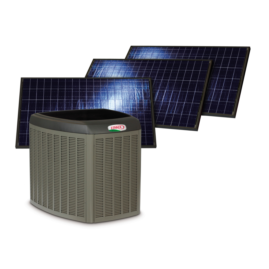
From each module, DC power is connected directly to an Enphase microinventer mounted below each module. 240VAC power from the microinventer passes through a renewable energy credit meter; next, through a disconnect ® switch and then ties into solar source breaker located in the Lennox SunSource XC21-060 (5-Ton) air conditioner. A2 — Site Plan... -
Page 3: A3 - Module Layout
A3 — Module Layout Module Layout SCALE: 1/8” = 1’- 0” SOUTH FACING ROOF: 3.18 KW PV ARRAY DETAILS (12) SW-265 solar PV AC modules in one AC circuit. (12) Enphase M215602LLS22 (240) 90MPH designed wind speed and exposure category B. Composition shingle roof on 1/2”... -
Page 4: B1 - Wiring Diagram
B1 — Wiring Diagram ® Figure 1. SunSource Home Energy System Electrical Layout Page 4... - Page 5 B1 — Alternate Wiring Diagram Page 5...
-
Page 6: B2 - Wiring Calculations
B2 — Wire Calculations AC Wire Sizing AC run from inverter through ACV disconnect to solar source Description breaker. 1. Design Current 15 A AC Maximum Current 15 A AC Microinverter Maximum Current 2. Wire Size Maximum average ambient Temperature De-rate 115°F (46°C) 0.87 Factor... -
Page 7: C1 - Pvwatts Calculations
C1 — PVWatts Calculations Page 7... - Page 8 C1 — PVWatts Calculations (continued) Page 8...
-
Page 9: D1 - Labels
D1 — Labels USED NEXT TO SOURCE CIRCUIT DISCONNECT FOR CIRCUIT BREAKER IN USED ON SOLAR SOLAR MAIN PANEL. DISCONNECT SWITCH −−−−−−−−−−−−−−−−−−− (DISCONNECT BOTH POWER SOURCES BEFORE PERFORMING REPAIRS OR OPENING EQUIPMENT SERVICE PANEL) USED ON HVAC DISCONNECT SWITCH USED ON UNIT CB10 PLASTIC COVER USED ON UNIT... -
Page 10: E1 - Pvc Ac Module Datasheet
E1 — Module Data Sheet PERFORMANCE Performance Performance At 800 W/M Under Normal Operating Cell Standard Testing Temperature (NOCT), Conditions AM 1.5 Maximum Power 265 Wp 187.6 Wp Open Circuit 38.1V 34.3V Voltage Maximum Power 31.9V 28.7V Point Voltage Short Circuit 8.82A 7.12A Current... - Page 11 E1 — Module Data Sheet (continued) DIMENSIONS − INCHES (MM) 37−1/2 (952) 11−3/8 (289) 41−3/8 (1051) (1676) 2−1/2 4−1/4 (108) 1−1/4 39−3/8 (1000) 1−1/4 (32) (16) 1−3/8 (35) Page 11...
-
Page 12: E2 - Microinverter Datasheet
Flashing Orange Producing power and not Microinverter ensures optimum performance for each communicating with Envoy associated solar module. The result is maximum energy production from the SunSource Energy System. Flashing Red Not producing power Enphase Microinverters for 3−Phase Applications... - Page 13 ENPHASE MICROINVERTER OPERATING PARAMETERS INPUT DATA (DC) Recommended Input Power (STC) 190−270W Maximum Input DC Voltage Peak Power Tracking Voltage 22V − 36V Operating Range 16V − 36V Min./Max Start Voltage 22V / 45V Max. DC Short Circuit Current Max. Input Current 10.5A OUTPUT DATA (AC) 208 VAC...
-
Page 14: E3 - Module Attachment Hardware Datasheet
E3 — Module Attachment Hardware QUICK MOUNT PV NOTE — Check with local building department to identify any unique Install the flashing below the upper shingle to allow water wind or snow load requirements that pertain to your jurisdiction. A to run around the raised penetration point. - Page 15 QUICK MOUNT PV (CONTINUED) Page 15...

Need help?
Do you have a question about the SunSource and is the answer not in the manual?
Questions and answers