Table of Contents
Advertisement
Advertisement
Table of Contents

Summary of Contents for SUNHOKEY I4
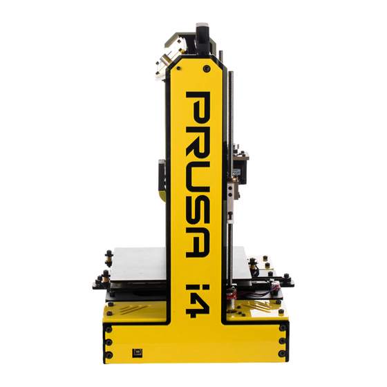
- Page 1 SUNHOKEY...
- Page 2 step1:Unscrew 4pcs of screws to take the heatbed apart from the base...
- Page 3 after step1 finishes, it looks like below...
- Page 4 Step2:install the frame Pay attention please, don't make the back to front.
- Page 5 Step3:fix the frame from bottom of base with screws: M5 X 12 2PCS...
- Page 6 Step4: install the leadrail of the X axis with screws: M3 X 30 8 PCS PS:please read STEP as a reference...
- Page 7 Step5: Pay attention if the leadrail is not level after you screw, please unscrew and adjust it to level.
- Page 8 Step6: install T8-leadscrew take the copper nut from the T8-leadscrew...
- Page 9 Step7: Fix copper srew nut to the leadrail with: M3 X 8 4 PCS...
- Page 10 Step8: Install and fix T8 leadscrew to the coupler...
- Page 11 Step9:Pay attention...
- Page 12 Step 10: Find the reason for the fault of step 9...
- Page 13 Step11: Fix the extruder holder to the X axis with screws: M3 X 8 4PCS Don't make the back to front...
- Page 14 Step12:Install the extruder to X Axis with screws: M5 X 12 3PCS Don't make the back to front...
- Page 15 Step13: Install stepper motor to the X Axis with screws: M3 X 8 4PCS...
- Page 16 Step14:Install belt to the X Axis: M3 X 8 4PCS...
- Page 17 Step15: Fix Turbofan with screws: M3 X 8 2PCS...
- Page 18 Step 16:Install X -ENDSTOP...
- Page 19 Step17:Install- X ENDSTOP M3 X 8 2PCS...
- Page 20 Step18:Wiring of the Cooling Fan Find No.1 (wire of 12V cooling fan)and connect it to the right position. pay attention: Red to Red. Black to Black...
- Page 21 Step19:Wiring of the Turbofan Find No.2 (12v turbofan) and connect it to right position Pay attention: Red to Red. Black to Black...
- Page 22 Step20:Wiring of Heater Find No.3(24v Heater) and connect it to the right position Pay attention: Red to Red, Black to Black...
- Page 23 Step21:Wiring of the thermistor of hotend Please find the thermistor of the hotend, and connect it to A13 of the Mainboard...
- Page 24 Step22:Wiring of the X-Axis stepper motor please find the stepper motor of the X-Axis, and connect it to X_MOT of the Mainboard...
- Page 25 Step23:Wiring of the extruder stepper motor Please find the stepper motor of the extruder, and connect it to E0_MOT of the Mainboard...
- Page 26 Step24: Install the Z-Axis ENDSTOP ensure the small screw tight Unscrew part touch the base complete...
- Page 27 Step25:Wiring of the Z-Axis endstop connect them together...
- Page 28 Step26:Install heating bed and Y Axis find the connector of the Y-Axis stepper and connect it to Y_MOT of the Mainboard...
- Page 29 Step27:Wiring of the Y-Axis stepper motor Connect the Y-Axis stepper motor to Y_MOT of the Mainboard...
- Page 30 Step28:Wiring of the thermistor of the heatbed get it through the hole Find the thermistor of the heatbed and connect it to A14 of the main board.
- Page 31 Step 29:Install the Y- Axis...
- Page 32 Step30:Install heatbed pay attention to the direction of the bed,must same with the picture shown.
- Page 33 Step31:Install heatbed rescrew the four screws as before they were taken apart and then block them.
- Page 34 Step32:install the heatbed rescrew the four screws as before they were taken apart and then block them.
- Page 35 Step33:Install Y-Axis endstop with: M3 X 8 2PCS...
- Page 36 Step 34:Wiring of the Y-Axis endstop...
- Page 37 Step35:Fix both acrylic frame Fix the the frame with power supply: M5 X 12 7PCS...
- Page 38 Step 36:Install LCD in the top acrylic frame connect the two wires with LCD first...
- Page 39 Step 37:Choose the correct voltage in the power supply. It's very important. this step is very important. if you don't make the voltage correctly, it will cause printer burnt after you finish previous installation, you should test the printer before you finish the rest installion. But before testing, you must choose the correct the voltage first.
- Page 40 Step 38:Test the printer after you confirm the correct voltage, please let the printer power on. Working status would be: the fan works, LCD can display like the picture.
- Page 41 Step39:Problems would occur while testing messing codes occur in the LCD, please press the buttoon like the picture no any characters in the LCD, please ensure you have done correct wiring.
- Page 42 Step40:Test the endstop after fixing the printed part, please turn the screw to very bottom, which can ensure the hotend don't touch the heatbed Fix the printed part of Z axis endstop to the place as the pictures show...
- Page 43 Step 41:Test all endstops 1. press the button ->turn it to 'Prepare' and press ->turn the button to ' Auto test the endstop with lcd home ' and press Z-Axis ENDSTOP is X-Axis ENDSTOP is Y-Axis ENDSTOP is Auto home Auto home Auto home...
- Page 44 Step42:Install the top acrylic framce fix the screws in the Put M3 *20screws into hole with tape the hole of top acrylic frame...
- Page 45 Step 43:Install top acrylic frame Fix top acrylic frame with M3*20 screws,ATTENTION:Acrylic frame is fragile, please screw it carefully...
- Page 46 Step44:Tie the wires...
- Page 47 A4 paper. Meanwhile, you can move the paper smoothly between them. I4 Facebook: this is our prusa i4 group : https://www.facebook.com/groups/573076312852368/ there are many people who have full experiencs in 3d printing. people are very friendly in this group . thank you! Welcome to follow Sunhokey Facebook: www.facebook.com/sunhokey.china...
Need help?
Do you have a question about the I4 and is the answer not in the manual?
Questions and answers