
Related Manuals for Sonostar CProbe

Summary of Contents for Sonostar CProbe
- Page 1 Wireless Probe Type Ultrasound Scanner CProbe User's Guide Prescription Statement “Caution: Federal law restricts this device to sale by or on the order of a physician”.
-
Page 2: Table Of Contents
目录 Section 1 INTRODUCTION........................1 1.1 Signs and Meaning........................1 1.2 TECHNICAL PARAMETERS......................2 1.3 INDICATIONS FOR USE......................... 2 1.4PRECAUTIONS & WARNINGS....................... 2 Section 2 GETTING STARTED........................1 2.1 UNPACKING............................ 1 2.2 INSTALLING APP........................... 4 2.3 STARTING PROBE......................... 7 2.3.1 Visual inspection......................7 2.3.2 Probe cleaning........................ - Page 3 5.2.1 Biological Safety......................... 22 5.2.2 Mechanical and Thermal Indices..................22 5.2.3 Acoustic Output Statement....................22 5.2.4 Operator Control Property....................23 5.2.5 Acoustic Power Settings...................... 24 5.2.6 ALARA..........................24 5.3 Electromagnetic Compatibilities....................24 5.3.1 Electromagnetic Emission....................25 5.3.2 Electromagnetic Immunity....................26 5.3.3 Recommended Separation Distance..................27 Appendix A Specifications ....................28 Appendix B Acoustic Output Data.......................
-
Page 4: Section 1 Introduction
Section 1 INTRODUCTION The Wireless Probe Type Ultrasound Scanner (Model: CProbe) is the new generation instruments for ultrasonography with the outstanding feature of wireless. Different with traditional ultrasound scanner with a cable connecting from probe to main unit, no cable appears at the end of the probe of the Scanners. The probe of the Scanner is highly integrated with ultrasound image processing, power management and a wireless signal provider to be connected by the main unit.The main units different with traditional devices are now changed to... -
Page 5: Technical Parameters
Waterproof: IPX5 1.3 INDICATIONS FOR USE The Wireless Probe Type Ultrasound Scanner (Model: CProbe) is intended for diagnostic ultrasound echo imaging, measurement, and analysis of the human body for general clinical applications including obstetrics (OB), gynecology (GY) and general (abdominal) imaging. - Page 6 PREACUTION 7: The device does not have shelf life. Its expected use lifeis 10 years. After 10 years, though the device still works normally, it is recommended to have it checked by the manufacturer. PRECAUTION 8: Useless components shall be disposed according to local regulations. ...
-
Page 7: Section 2 Getting Started
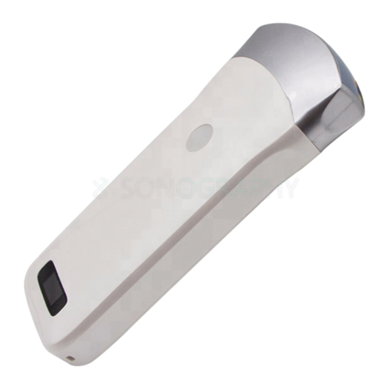
Section 2 GETTING STARTED FOR YOUR PROTECTION, please read these safety instructions completely before applying power to, or operating the system. Too high ultrasonic intensity and / or long exposure time may cause injury. Caution Please do not apply the probe of this machine to the scope not covered in this manual. - Page 8 Product schematic diagram Probe On Off/ freeze Battery capacity display Wireless signal status display display Picture 2-1 L-probe Probe On Off/ freeze Wireless signal status display display Battery capacity display Picture 2-2 C-probe CT-probe CL-probe Upper probe working status display display On Off/ freeze Under probe working status display...
- Page 9 Switch the probe: press and hold the switch for three seconds Working state display: indicator lamp indicates the position of the convex array to work with the convex array probe, and indicator linear array position to work with the linear array probe Charging support: this probe only supports wireless charging.
-
Page 10: Installing App
2.2 INSTALLING APP The software is installed by computer after connecting iPad or iPhone to computer. Before software installation, please make sure your computer has installed the Apple iTunes. And please copy the wireless scanner Application to the computer disk. There are two separate applications, one for IPAD, another for IPHONE. - Page 11 2)Choose menu Add File to Library... 3) Choose Application for IPAD or IPHONE, confirm it.
- Page 12 4)Choose IPAD, Enter into Apps menu, the Apps option would appear the added application. Choose Install the WirelessScan Application. 5) Click Install, the menu changes to Will Install, choose Apply. Startto install the application.
-
Page 13: Starting Probe
Abnormal probes can cause electric shock or injury to people. Waring Therefore, once any abnormalities are found, you must immediately stop using the probe and contact Sonostar. 2.3.2 Probe cleaning Ultrasonic probes should be cleaned and disinfected before and after ultrasound examination. -
Page 14: Wireless Connection
In the event of any of the above anomalies, the ultrasound Caution imaging diagnostic apparatus may be defective, please contact SonoStar. The Wireless Connection Indicator and the Battery Capacity Indicator on the probe may be invisible before the probe is turned on. -
Page 15: Section 3 App Operations
Section 3 APP OPERATIONS 3.1 ULTRASOUND scanning ⑴ ⑵ ⑶ ⑷ Main interface (Figure 3-1) The meaning of each icon: 1.Gain +: increase image gain. 2.Gain -: reduce image gain. 3. Focus: adjust the focus position of the image. 4.Dynamic range: adjust the dynamic range of the image. 5.Frequency: can change the working frequency of the probe. - Page 16 Mode introduction: Picture 3-2 Color Doppler imaging mode Color Doppler imaging mode, Picture 3-2: 1.Color sampling frame: change the direction of the color sampling frame. 2.Gain +: increase color blood flow gain. 3.Gain -: reduce color flow gain. 4.Move, Zoom: change the position and size of the color sampling frame by clicking and moving with your finger.
-
Page 17: Patient Information Input
Picture 3-4 Pulse Doppler imaging mode Pulse Doppler imaging mode, Picture 3-4: 1.Gain +: increase pulse gain. 2.Gain -: reduce pulse gain. 3.Deflection angle: used to change the angle of the spectrum sampling line in real-time scanning state. 4.Sampling frame: change the size of the sampling volume. 5.Correction angle: used to change the angle of the blood flow direction cursor. -
Page 18: Data Measurement
Picture 3-6 Patient Information Editing Interface 3.3.3 Data measurement In B/M mode, the position of the sampling line can be adjusted by tapping the moving circle on the screen with your finger (as shown in Picture 3-7 below). In the frozen state of B/M mode, click the M mode area, the moving circle can appear, the heart rate can be measured, and the default number of cardiac weeks is 5 weeks (five-segment, that isfive heartbeat intervals are taken and the average heart rate is calculated). - Page 19 Picture 3-9 Measurement function After selecting the “LENGTH” length measurement function, click on the two points to be measured in the frozen screen, the measurement trajectory will appear, click the moving point on the trajectory line (as shown in the middle of Figure 3-7), move the trajectory, adjust the length. The size of the real-time measurement data is displayed at the top right of the screen.
-
Page 20: Report Download
Picture 3-10 Up to 4 sets of data can be measured in the same frozen screen. After the measurement, press “Clear X” to delete all measurement results. If you want to delete a measurement, click on the measurement data at the top right of the screen to display the result. 3-11,Within the same freeze frame, the measurement can be at most four sets of data. -
Page 21: 5Image And Vedio Storage
Figure 3-12 pop-up patient information interface. Click on "report",pop up the interface below as shown in figure 3-13, click on the "tip" box, the user can input content in dialog box. Click on download icon " "on the lower right of the page,then the report can be downloaded.The report are stored automatically in the smart terminal display system (apple mobile phone, or tablet) photo album. -
Page 22: Vedio Storage
图 3-14 3.3.5.2 Vedio storage Click on "save vedio" on the bottom right in above interface (FIG. 3-14),then the vedio starting from the operation within 100seconds are stored in the smart terminal display system (apple mobile phone, or tablet) photo album. 3.3.6 Image and vedio review Open the photo album of the smart terminal display system (apple mobile phone, or tablet),then review the saved image and vedio. -
Page 23: Section 4 Mainteance
Section 4 MAINTEANCE 4.1 PROBE CHARGING When battery is insufficient,the probe needs charging. Pull out the rubber plug at the end of the probe,connect probe and the USB charger by USB cable as shown in figure 4-1.When charging,battery capacity indicator light is flashing.The grid shows the electricity sufficiency. -
Page 24: Cleaning And Disinfection
4.3 CLEANING AND DISINFECTION The probe needs to be cleaned before using. To clean the probe, Use a soft cloth dampened with isopropyl alcohol (or an appropriate hospital cleaning agent) to wipe the Probe until it is thoroughly cleaned. If you use a detergent solution to clean the instrument, remove all residual detergent. Dry the instrument with a clean, soft cloth. -
Page 25: Proudct Maintenance And Protection
4.7Proudct maintenance and protection 1, this product usage and storage conditions shall comply with the environmental conditions of section 1.5 in this manual. 2, The prouduct power suppy shall be in accordance with section 1.6 of this manual. 3, If Stop using this product for a long period of time, ensure charging at least twice a week, every time not less than 1 hour. -
Page 26: Section 5 Safety
Section 5 Safety The operation safety is the most important concern of the designer . To ensure the safety and efficiency of the system, the operator should read carefully about this chapter before using the system. 5.1 Safety Instructions Read and understand all precautions in this manual before using the system. Keep this manual with the system at all times. -
Page 27: Accessories Safety
● During usage, if there is any software bug, the user can do feedback via company email: sonostar@sonostar.net, then the company will do analysis and modification according to the bug, if there is needs for update, there will be update notification via email to remind the user to do... -
Page 28: Principles Of Using Acoustic Power
5.2 Principles of Using Acoustic Power 5.2.1 Biological Safety Diagnostic ultrasound is recognized as being safe, but the risk of biological effects exists when using it in high exposure levels and long exposure times. Thus ultrasound should be used in a prudent manner to provide medical benefit to the patient. -
Page 29: Operator Control Property
●The system changeability ●Changeability and accuracy of measurement ●Possible operating conditions and testing numbers needed to obtain displayed result accuracy of the diagnostic system ●Whether the display accuracy depends on specific system combination, mode combination , probe component and launch mode combination, or all of above ●Algorithm accuracy of the system software used to calculate the MI/TI ●Approximation engineering method used in real time computation 5.2.3.2 Differences between Actual and Displayed MI and TI... -
Page 30: Acoustic Power Settings
the more acoustic output power increased over a period of time. ■ The receiver control The receiver control does not affect the acoustic output, including gain, dynamic range, and image processing, etc. Therefore, in the image optimization, should adjust the receiver control to optimize images firstly, the second are through direct control and indirect control. -
Page 31: Electromagnetic Emission
Guidance and manufacturer’s declaration - electromagnetic emission The CProbe Wireless Probe Type Ultrasound Scanner is intended for use in the electromagnetic environment specified below. The customer or the user of CProbe Wireless Probe Type Ultrasound Scanner should assure that it is used in such environment. -
Page 32: Electromagnetic Immunity
5.3.2 Electromagnetic Immunity Guidance and manufacturer’s declaration - electromagnetic immunity The CProbe Wireless Probe Type Ultrasound Scanner is intended for use in the electromagnetic environment specified below. The customer or the user of the CProbe Wireless Probe Type Ultrasound Scanner should assure that it is used in such an environment. -
Page 33: Recommended Separation Distance
The CProbe Wireless Probe Type Ultrasound Scanner is intended for use in an electromagnetic environment in which radiated RF disturbance are controlled. The customer or the user of the CProbe Wireless Probe Type Ultrasound Scanner can help prevent electromagnetic interference by... -
Page 34: Appendix A Specifications
Appendix A Specifications EN 60601-1 (IEC 60601-1), Medical electrical equipment Part 1: General requirements for basic safety and essential performance, Class I, BF, continuous operation EN 60601-2-37:2008 (IEC 60601-2-37:2007), Medical Electrical Complied Equipment Part 2-37: Particular Requirements for the Basic Safety and Essential Standards Performance of Ultrasonic Medical Diagnostic and Monitoring Equipment EN 60601-1-2:2007 (IEC 60601-1-2: 2007), Class A... -
Page 35: Appendix B Acoustic Output Data
Appendix B Acoustic Output Data These data are acquired through the test report of IEC 60601-2-37. Transducer Model: CProbe, SN:WSPBGCA042 Operating Mode:Bmode Non-scan Index label Scan ≤1 >1 Non-scan aprt aprt Maximum index value 0.65 0.16 1.17 r.α 13.31 min of [P α... - Page 36 Transducer Model: CProbe, SN:WSPBGCA042 Operating Mode:B+M mode Non-scan Index label Scan ≤1 >1 Non-scan aprt aprt Maximum index value 0.65 0.16 0.12 0.37 1.17 r.α 13.31 13.11 min of [P 7.68 α ta.α 2.40 2.19 Associated acoustic 4.70 parameters z at max I 4.70...
Need help?
Do you have a question about the CProbe and is the answer not in the manual?
Questions and answers