Table of Contents
Advertisement
Quick Links
- 1 Parameters of Vsp-F2L4 Controller
- 2 Chapter 1 Brief Introduction of Vsp-F2L4 Controller
- 3 Spec (Adjust and Set the Parameters of Led Screen)
- 4 Chapter3. Control Software of Vsp-F2L4 Controller
- 5 Installation and Running Environment for Control Software of Vsp-F2L4 Controller
- 6 Appendix 1 Signal Output Cutting Method of Vsd-F2L4 Controller (Important)
- Download this manual
The Manual of VSP-F2L4 Controller
Contents
Chapter 1 Brief Introduction of VSP-F2L4 Controller................................................................... 2
1.1 Parameters of VSP-F2L4 controller..............................................................................................2
1.2 The signal connection way of LED screen................................................................................... 3
1.3 Function Introduction for VSP-F2L4 Controller's Buttons and Interfaces..................................5
1.3.1 Front Side Introduction of the VSP-F2L4 Controller........................................................5
1.3.2 Introduction for Back Side of the VSP-F2L4 Controller.................................................. 6
Chapter2 Key-press operation of VSP-F2L4 controller...................................................................7
2.1. Use the buttons to switch input signal types................................................................................7
2.2 Adjust the Parameters by Key-press............................................................................................. 7
2.2.1 Product............................................................................................................................... 8
2.2.2 Spec (Adjust and set the parameters of LED screen)........................................................ 8
2.2.3 Address Setting.................................................................................................................. 9
2.2.4 Color Test......................................................................................................................... 10
2.2.5 IP Address.........................................................................................................................11
2.2.6 Language (Language Select)............................................................................................11
2.2.7 Date Save..........................................................................................................................11
Chapter3. Control software of VSP-F2L4 controller.....................................................................12
3.2 Communication Setting.............................................................................................................. 13
3.2.1 Serial Port (COM Port) Setting through USB Cable.......................................................13
3.2.2 Network Port Setting........................................................................................................14
3.3 Parameters Introduction of Control Software.............................................................................15
3.4 Address Setting........................................................................................................................... 17
3.4.1. Address setting method 1: (Not normally used)............................................................. 17
3.4.2 The Method 2 for Address Setting: Multiple Setting (whole screen setting)............... 19
3.4.3 The method 3 for Address setting: Intelligent Settings................................................... 20
3.5 Color temperature adjustment.....................................................................................................22
3.5.1 Single panel (Box) color temperature adjustment........................................................... 23
3.5.2 LED board (module) color temperature adjustment........................................................25
3.6 Manufacturer Set.........................................................................................................................26
Appendix 1 Signal output cutting method of VSD-F2L4 controller (Important).........................27
Signal Horizontal Segmentation of VSP-F2L4 controller................................................................27
(Applicable to all products).............................................................................................................. 27
Signal Vertical Segmentation of VSP-F2L4 Controller....................................................................28
Ⅱ
Failure Analysis and Troubleshooting....................................................................29
1
Advertisement
Table of Contents

Summary of Contents for GLUX VSP-F2L4
-
Page 1: Table Of Contents
1.3 Function Introduction for VSP-F2L4 Controller’s Buttons and Interfaces........5 1.3.1 Front Side Introduction of the VSP-F2L4 Controller............5 1.3.2 Introduction for Back Side of the VSP-F2L4 Controller..........6 Chapter2 Key-press operation of VSP-F2L4 controller..............7 2.1. Use the buttons to switch input signal types................7 2.2 Adjust the Parameters by Key-press..................... -
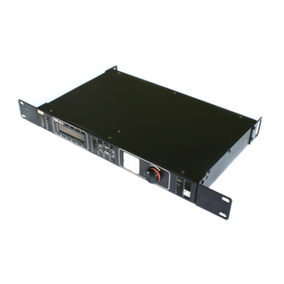
Page 2: Chapter 1 Brief Introduction Of Vsp-F2L4 Controller
VSP-F2L4 control system is researched and developed by Glux independently, it is the third generation and suitable for the new generation LED display products of Glux. It is a set of network transmission, optical fiber transmission, and with image scaling, image mirror functions, and supported 1080 p resolution. - Page 3 Please choose a proper way according to your usage. Method 1: For use without the Glux signal divider: Link the LED screen with VSP-F2L4 controller by signal cable. It means that signal is transmitted to the LED screen directly from the controller’s output port (OUT1~OUT4).
- Page 4 System signal connection method 2 (Transmission distance≤150m) Signal→by CAT6 Ethernet cable→to Signal divider→by signal cable→to screen System signal connection method 3 (Transmission distance≤10Km) Signal→by optical fiber cable→to Signal divider→by signal cable→to LED screen The optical fiber cable type should be single mode. Which method you choose will depend on the control distance and the size of LED screen.
-
Page 5: Front Side Introduction Of The Vsp-F2L4 Controller
1.3 Function Introduction for VSP-F2L4 Controller’s Buttons and Interfaces 1.3.1 Front Side Introduction of the VSP-F2L4 Controller (1) LCD display interface: Mainly showing the setting and product information, shown as below. Input DVI 1920×1080P 60 Output 1024×768P 60 Brightness MBI5041 CYSN39 IP 192. -
Page 6: Introduction For Back Side Of The Vsp-F2L4 Controller
1.3.2 Introduction for Back Side of the VSP-F2L4 Controller (6) DMX512 signal input port. (7) Adjust video synchronous In/Out port (8) Lan-100M is the network communication port that is used to communicate with the control software on computer to set the LED panel parameters. -
Page 7: Chapter2 Key-Press Operation Of Vsp-F2L4 Controller
Chapter 2 Key-press operation of VSP-F2L4 controller 2.1. Which buttons to switch input signal types Please simultaneously press the three keys SEND/DVI, SEL/SDI1, ESC/SDI2 to enter the mode of switch signal input. Now press the SEND/DVI key for DVI input signal. -
Page 8: Product
Port: Select a connecting controller port. Series: Select a style of the product. Cut Signal: Cut or link the transmission signal of the VSP-F2L4 controller. Test Mode: Test and check the color of the LED screen. DMX512 on/off: Please select OFF if there is no DMX512 signal input to the controller. - Page 9 Function IP Address Language > Data save Press SEL/SDI1 to enter the Save menu and rotate the control knob to select the Save. Then Select it, you will see the symbol #. Function # Save Exit Rotate the control knob to Save. Then Press SEND/DVI to send, and Press ESC/SDI2 to exit Function...
-
Page 10: Color Test
4000,5500,6500,8000 usually choose 6500. 2.2.5 IP Address IP address setting for VSP-F2L4 controller. Please make sure the IP address of the controller and your computer is in the same LAN network, but different IP values. It means the 1st-3rd segment addresses should same, but the last segment is different. -
Page 11: Chapter3. Control Software Of Vsp-F2L4 Controller
3.1 Installation and Running Environment for Control Software of VSP-F2L4 Controller Users can install the VSP-F2L4 control software in the computer to set the parameters of the LED screen. At present, the control software only supports Windows XP, Windows 7 and Windows 8 operating system. Apple, Android, Linux operating system are not supported. -
Page 12: Communication Setting
There are two ways to communicate each other between control computer and VSP-F2L4 controller, through USB cable or Ethernet cable. It means that you only need one USB or RJ45 cable connect the computer with controller to set the LED screen’s parameter. -
Page 13: Network Port Setting
3.2.2 Network Port Setting If the controller and the computer are connected via the Network port, set the IP address correctly before setting the parameters. And then click the option "Ping" in the Network port communication. Please make sure the IP address of the controller and the control computer on the same LAN network segment, it means the 1st-3rd segment addresses should same, but the last segment is different. -
Page 14: Parameters Introduction Of Control Software
3.3 Parameters Introduction of Control Software Controller Port: Select a port of VSP-F2L4 controller that connected the LED screen. All means all ports. Port A, B, C, D respectively represent signal output ports OUT1, OUT2, OUT3, OUT4 of the VSP-F2L4 controller. - Page 15 Import: Import a file to recovery the parameter data. Read: Read the parameters from the current VSP-F2L4 controller (Usually not need to use). Send: Click the “Send” button to check the change of LED screen after you complete the setting of the parameters.
-
Page 16: Address Setting
3.4 Address Setting There are 3 methods for set the screen display address by this control software: single setting, multiple setting (whole screen setting) and intelligent setting. Usually we only use the multiple setting or intelligent setting to set the screen’s display address, as shown below: 3.4.1. -
Page 17: The Method 2 For Address Setting: Multiple Setting
remember to save your settings in the “Parameters” interface when you finish setting all LED screens addresses. Otherwise, once you reboot the controller, the data for the address setting will be lost. Attention Please : Single setting will usually only be used for some special requirements of display. -
Page 18: The Method 3 For Address Setting: Intelligent Settings
Controller port:Select correct control port(A、B、C or D port) ; Connect mode:There are 8 kinds of signal connect modes ( Mode1~Mode8) for the user to choose. You can also preview the signal connect mode on the right figure by click the Mode1~Mode8: Columns:Represents how many columns of the LED screen charged by the controller selected port. - Page 19 Controller Port: Select correct controller port (Port A、 B、 C、 D represent port OUT1、 OUT2、OUT3、OUT4). Divider Port: Select a correct SDV signal divider port. For further detail instruction to each port of signal divider please see the SDV08 manual. Start MAC-Address: The default value is 0 , please refer to the previous single setting section for further details.
- Page 20 For example, one LED screen , size: 4pcs x 3pcs(W x H); use VSP - F2L4 controller’s OUT2 output port; signal divider’s port 1 ; Signal connect mode: mode 7. See the following red arrow connection mode: Address setting showed as follows(Click one by one along the address module) 1) Select the B port in the controller port, select port 1 in the signal divider port, then build and number the LED panels as the following: Undo :...
-
Page 21: Color Temperature Adjustment
click the “Send” button. Attention please: When you finished to set the address, please remember to click the “Save” button in the parameters interface no matter which setting method you choice. Otherwise, the address setting data will be lost once you reboot the controller. The summary steps for address setting Step 1:... -
Page 22: Single Panel (Box) Color Temperature Adjustment
3.5.1 Single panel (Box) color temperature adjustment For example: LED Screen, size: 4pcs×3pcs(W×H, signal transmission from port A of the VSP-F2L4 controller. The color brightness of the fourth panel is higher than the others. Take adjusting the fourth LED panel as an illustration. - Page 23 Step4: Drug the cursor and adjust the color temperature value. Selecting “X9” will change the color temperature value of RED, GREEN and BLUE at the same time. Select “X3”will adjust its R/G/B values separately. Step5: Click “Send” button to check the color of the fourth panel and compare with other panels.
-
Page 24: Led Board (Module) Color Temperature Adjustment
Step3, Step4, Step5 3.5.2 LED board (module) color temperature adjustment The methods and steps are similar as the single panel color temperature adjustment. The difference is on the 2 step. Please select the correct LED module of the LED panel that you will adjust instead of the “Whole Box” button as shown below. Summary: The range of one color temperature adjusting is 0~320. -
Page 25: Manufacturer Set
(1) Adjust the value of R, G and B for the three (2) Adjust the value of R, G and B for one Colors at the same time and proportion color at the same time and proportion. (3) Adjust the compensation value of R, G and B separately for one color. Suggestion: It is better to have the LED screen display red;... -
Page 26: Appendix 1 Signal Output Cutting Method Of Vsd-F2L4 Controller (Important)
(Important) There are four serial network signal (OUT1~OUT4,represented by A, B, C, D) and two serial optical fiber signal (OUT1~OUT2) for VSP-F2L4 controller. A, B, C, The first optical fiber output signal equates the sum of network OUT1 and OUT2 output signal, that is, signal A and signal B. -
Page 27: Signal Vertical Segmentation Of Vsp-F2L4 Controller
W≤1792, H max=342 W≤2048, H max=300 Signal Vertical Segmentation of VSP-F2L4 Controller The first way: Output resolution for each controller port is 512×1080(W×H) The fixed output resolution for each controller port is 512×1080 ( W×H) when the port resolution set to W=1920,768≤H<1280 as shown below picture. -
Page 28: Appendix Ⅱ Failure Analysis And Troubleshooting
Appendix Ⅱ Failure Analysis and Troubleshooting 1.If you are prompted that IP connection failed, please check whether the IP of network port set correctly and network cable is workable and the controller IP and the computer IP are in the same LAN network. 2. - Page 29 computer, please check whether you have installed the USB driver correctly. After installing the USB driver, some computers need to restart and re-plug the USB cable in order to identify the communication port, or need to update the USB driver in the Device Manager, or re-open the control software again.
Need help?
Do you have a question about the VSP-F2L4 and is the answer not in the manual?
Questions and answers