Table of Contents
Advertisement
The contents of this envelope are the property of the owner.
Be sure to leave with the owner when installation is complete.
IMPORTANT: Please read the installation instructions
thoroughly before beginning. Installation of any item is
easier if the vehicle is clean and free of debris.
These instructions are only valid for attachment to RTV-X900,
RTV-X1100C, RTV-X1120, RTV-XG850, and RTV-X1140 utility vehicles.
Note: Front Heavy Duty Springs (V5218) or Heavy Duty Spring Damper
Assembly (V5219) are required for RTV-X900, RTV-X1120, and RTV-XG850.
Heavy duty springs come standard on RTV-X1140 model.
For RTV-XG850, installation of K7591-97900 grill guard kit is required.
Approximate Installation Time: 1-2 hours
D
o not attempt to install or operate this
plow until you read and understand all
warnings and instructions in this manual or
on the plow. Failure to read all warnings
and instructions could lead to serious injury
or death.
California Health and Safety Proposition 65 Warning: This product may contain
chemicals known to the state of California to cause cancer and birth defects or other reproductive harm.
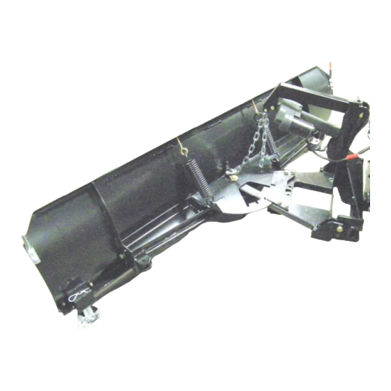
V5008
Kubota RTV
72" Snow Blade
ADDED
WEIGHT
Curtis Cabs, blades and general accessories
add additional weight to the base vehicle. All
Curtis accessory weights are listed in product
brochures. Deduct the accessory's total weight
from the vehicle's rated capacity and never
exceed the vehicle's rated capacity including
driver and passenger.
manual p/n: 77700-05199 (V5008P1)
(Rev. D) 11/20/2018
p. 1 of 15
Advertisement
Table of Contents

Related Manuals for Kubota V5008


Summary of Contents for Kubota V5008
- Page 1 V5008 Kubota RTV p. 1 of 15 72” Snow Blade The contents of this envelope are the property of the owner. Be sure to leave with the owner when installation is complete. IMPORTANT: Please read the installation instructions thoroughly before beginning. Installation of any item is easier if the vehicle is clean and free of debris.
- Page 2 p. 2 of 15 SAFETY INFORMATION: WARNING: Cabs, blades, and general accessories add additional weight to the base vehicle. Deduct the accessory’s total weight from the vehicle’s rated capacity including driver and passenger. Never operate the vehicle outside of its rated weight capacity. WARNING: Exposure to Carbon Monoxide can cause illness, serious injury or death.
- Page 3 p. 3 of 15 1. PRELIMINARY: (for all models) 1.1 Remove and discard the two M12 bolts holding brush guard or front bumper to the front suspension cross member. The two bolts will not be reused with the snow blade mounting frame installed. See Fig 1.1. 1.2 Open the vehicle hood.
- Page 4 p. 4 of 15 3. CONTROL SWITCH & WIRING: (for all models except RTV-XG850) (for RTV-XG850, see steps 3.1a-3.3a on the next page) 3.1 See photo 1 and 2 for the approximate location for mounting the power relay. Per photo 1, locate the driver’s side black, plastic, molded side panel.
- Page 5 p. 5 of 15 RTV-XG850 Wiring: 3.1a Remove under seat storage compartment and panel to access fuse compartment. If equipped with accessory wiring harness, fasten power relay and ring terminal at end of 16 ga. black ground wire using one of the existing bolts. If not equipped with accessory fuse box, drill 1/4”...
- Page 6 p. 6 of 15 3. CONTROL SWITCH & WIRING (cont’d.): 3.4 From the area in front of the battery route the free end of the rear wiring harness in front of the radiator, following the (for all models) path of the vehicle wiring harness through the wiring tray, into the front compartment under the hood , and to the area under the driver’s side end of the dash.
- Page 7 p. 7 of 15 Steel 5. Trip-Frame to Moldboard Assembly Moldboard (for all models) Moldboard 5.1 Per fig 5.1, locate the steel moldboard, trip frame, two 1/2-13 x 2” bolts, and two 1/2-13 Nylock lock nuts. Apply all-season grease to the mating sur- faces on the trip frame and moldboard rib.
- Page 8 p. 8 of 15 7. A-Frame Installation A-frame (for all models) Apply grease here 7.1 Per fig 7.1, locate the A-frame, blade angle handle, handle spring, one 1/2-20 x 3.5” hex head bolt, one 1/2-20 conical locking hex nut, and one 1/2” wash- er.
- Page 9 p. 9 of 15 Blade angle slots. 7.4 Install the blade angle handle. For easiest installa- Align slots in center tion, be certain A-frame is oriented as in fig 7.4, position. with the trip frame blade angle slot aligned with the A-frame angle slot in the center position.
- Page 10 p. 10 of 15 8. Chain/Winch Shackle Installation (for all models) 8.1 Locate the Lift Chain Shackle per figure 8.1 8.2 Per Fig 8.2, slide Lift Chain through shackle then insert the clevis pin on the lift chain shackle into the lifting hole on the trip frame.
- Page 11 p. 11 of 15 Lift Arm 10. Attach Lift Arm to Lift Frame (for all models) 10.1 Apply grease to the pivot holes of the Lift Arm, Actua- tor, and the Upper Lift Frame. Place the rod end of the Actuator between the vertical plates of the Lift Frame, line up lower hole in lift frame with rod hole in actuator.
- Page 12 p. 12 of 15 12. Attach Jack Leg in Upper Stored Position (for all models) 12.1 Install the Rear Jack Leg in the stored position. Place the two pins on the rear jack leg into the two holes on the driver’s side lift frame vertical plates.
- Page 13 p. 13 of 15 14. Attach A-Frame to Lift Frame (for all models) 14.1 Apply grease to the pivot holes in the rear of the A-Frame and the lower Lift Frame. 14.2 Place the Rear Outer Tabs of the A-Frame on both sides of the Lower Outer tabs on the Lift Frame.
- Page 14 V5008 Kubota RTV 72” Snow Blade Service Parts Diagram p. 14 of 15...
- Page 15 V5008 Kubota RTV 72” Snow Blade Service Parts List p. 15 of 15 Part Description Kubota Part Number Part Number Qty. Cutting Edge 70000‐01088 KAF25‐039E Steel Moldboard 70000‐01092 SM‐20.5V72‐12W Blade Marker Kit (sold as pair) 70000‐01011 1TBP37 Trip Spring (sold separately) 70000‐01096 LAF25‐039SP Hardware Kit 77700‐05221 KX9HWK‐UTP Trip Frame 70000‐01093 KAF25‐039P8 A‐Frame 77700‐05222 1TBP29LD Lift Frame 77700‐05223...
Need help?
Do you have a question about the V5008 and is the answer not in the manual?
Questions and answers