Table of Contents
Advertisement
Advertisement
Table of Contents

Summary of Contents for Scott QuadScan II 7400
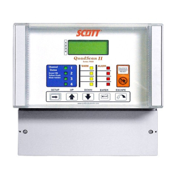
- Page 1 QuadScan II MODEL 7400 Four Channel Receiver and Controller Operation & Maintenance Manual Rev: 7400 Rev F Warning: Read & understand Date: 5/02/08 contents of this manual prior to ECN 129028 operation. Failure to do so could Part Number: 087-0023 result in serious injury or death.
-
Page 2: Table Of Contents
TABLE OF CONTENTS INTRODUCTION ..........................1 Important Safety Issues & Warnings .......................1 Unpacking................................1 General Description............................2 Figure 1 - Model 7400 QUAD-SCAN II Complete Assembly................3 QUICK START ..........................4 Quick Start Programming Menu Tree ......................5 RECEIVER/CONTROLLER......................8 General................................8 NEMA-4X Wall Mounted Enclosure........................9 Figure 2- Model 7400 QuadScanII ........................9 Figure 2A –... - Page 3 Figure 9 - Battery Backup (P/N 096-0719)......................19 Outline & Interconnection Wiring........................19 SYSTEM OPERATION........................20 General................................20 Display Readings .............................20 Visual Indications (LEDs)..........................20 Current Loops ..............................21 Current Loop Outputs .............................22 Alarm and Relay Operation..........................22 Figure 10 - Alarm Set For Increasing or Decreasing Gas Concentrations ..........23 Latching Alarms...............................24 Energized Relays (Fail Safe) ...........................24 Common Alarm Relays............................24...
- Page 4 General................................65 Channel Test Setup ............................65 Table 2 - Identify and Locate Possible Malfunctions During System Failure..........67 SPARE PARTS ..........................68 SCOTT HEALTH & SAFETY WARRANTY...................70 CONTACTING SCOTT HEALTH & SAFETY................71 TECHNICAL SPECIFICATIONS ....................72 FACTORY DEFAULT SETTINGS ....................73 Table 3 - Factory Default Settings for Receiver/Controller................73 CUTOMER WORK SHEET ......................74...
- Page 5 LISTING PROGRAMMING SELECTIONS Channel 1 ..................74 LISTING PROGRAMMING SELECTIONS Channel 2 ..................76 LISTING PROGRAMMING SELECTIONS Channel 3 ..................78 LISTING PROGRAMMING SELECTIONS Channel 4 ..................80 LISTING PROGRAMMING SELECTIONS REMOTE RELAYS ...............82 APPENDIX A ..........................84 Programming Example 1..........................84 Programming Example 2..........................103 Programming Example 3..........................108 Table of Contents 4...
-
Page 6: Introduction
Examine each item for external damage. If there is any damage or if any item is missing, notify the factory at: Scott Health & Safety Customer Service 4320 Goldmine Rd. Monroe, NC 28110 USA Phone: (704)291-8300... -
Page 7: General Description
3 channels to be purchased within the 4 channel unit. Only the number of channels purchased will be activated for monitoring in this unit. If you wish to activate additional channels when less than 4 are purchased, contact the Scott Health & Safety factory to purchase the activation codes. -
Page 8: Figure 1 - Model 7400 Quad-Scan Ii Complete Assembly
Model 7400 QUAD-SCAN II Remote Relay Box P/N 096-2691 Comes with 10 feet of Cable (See Figures 10 & 11 for Mounting Details & Wiring Interconnect) Battery Backup P/N 096-0719 (See Figure 14 for Mounting Details & Wiring Interconnect) Figure 1 - Model 7400 QUAD-SCAN II Complete Assembly 3 of 116... -
Page 9: Quick Start
7. If optional remote relays are to be used, connect per the “Optional Remote Relays” section of this manual. 8. For problems in startup, refer to the “Troubleshooting” section of this manual. Otherwise contact your local Scott Health & Safety representative or the Scott Customer Support team. 4 of 116... -
Page 10: Quick Start Programming Menu Tree
Quick Start Programming Menu Tree 5 of 116... - Page 11 System Menu Channel Menu Security Menu Touch Enter Key Touch Enter Key Touch Enter Key Version 1.# (1) ON/OFF/IHB: ON Security Options Move through options with Move through options with Move through options with UP/Down Key UP/Down Key UP/Down Key Adjust Contrast (6) Sensor: 4-20mA (1) Change Password...
- Page 12 4. The relays can be configured for any configuration desired. W = warn, A = alarm, F = fail and the numbers 1 – 4 designate channel number. & = And logic, = Or logic and ( ) are used to group channels. Refer to the “Remote Relay Operation”...
-
Page 13: Receiver/Controller
An optional battery backup assembly is also available providing 2.5 amp-hours of DC power to the unit. Factory supplied battery (Scott Health & Safety P/N 004-0002) is a Sonnenschein Part No. A212/35, 12 volt 2.5 amp hour battery. -
Page 14: Nema-4X Wall Mounted Enclosure
Failure to do so may be dangerous. Dispose of batteries per applicable local, state and federal regulations or contact Scott Health & Safety or your local Scott authorized distributor. NEMA-4X Wall Mounted Enclosure The enclosure measures 9.32 inches high x 9.19 inches wide x 5.38 inches deep (233 mm x 203 mm x 136 mm). It provides a watertight, dust tight and corrosion resistant enclosure for outdoor or indoor mounting. -
Page 15: Display/Function Assembly
Display/Function Assembly The individual visual display of absolute value of the gas concentrations, alarm status, and channel status for all active channels provides the status of the gas/flame detection system. Operator intervention and/or automatic alarm corrections can be made from the information displayed by this unit. Gas Concentration is displayed on a LCD in units of PPM, PPB, % and none (flame applications) in any combination of the four. -
Page 16: Cpu/Power Supply Boards
NOTE: During the programming mode, if a switch is not activated for 20 minutes, the display automatically returns to the gas concentration display and all previous programming will be lost. Figure 3 - Model 7400 Front Panel Push Buttons CPU/Power Supply Boards The power supply board is located on the inside back surface of the enclosure. -
Page 17: Figure 4 - Terminal Strip Layout
Terminal blocks are provided for the following input and output requirements: TB1 – 2, 3, or 4 wire 4 – 20 mA inputs for Channels 1 and 2 TB2 – 2, 3, or 4 wire 4 – 20 mA inputs for Channels 3 and 4 TB3 –... -
Page 18: Installation
Installation The installation information is presented in three sections: Selecting the appropriate physical location Methods of physical mounting Directions for wiring Note: Remote relay installation is covered in a separate section. Selecting the Physical Location The specific location for the receiver/controller is the responsibility of the user. Use the following guideline to determine the appropriate location for the unit: Do not exceed the temperature range of -13º... - Page 19 3. Move the hinged section away from the side of the enclosure, disengaging it from the base. 4. Tilt the assembly away from the base enclosure and unplug the ribbon cable from the display circuit board. Power must be off before removing ribbon cable. 5.
-
Page 20: Figure 5 - Mounting Dimensions Of Model 7400
Figure 5 - Mounting Dimensions of Model 7400 15 of 116... -
Page 21: Directions For Wiring
Directions for Wiring Remove the cover plate located at the front bottom of the enclosure; this will expose all terminal blocks. The main I/O – power supply board is labeled with the appropriate function and wire designation to implement correct wire hook up. Refer to Figure 6 for the terminal block layout. -
Page 22: Figure 6 - Terminal Block Arrangement On Main I/O – Power Supply Board
Figure 6 - Terminal Block Arrangement on Main I/O – Power Supply Board Figure 7 – Transmitter Wiring to Model 7400 CAUTION: All relay contacts are rated 5A Resistive Load. Any in-rush current above this value can cause damage to the unit Dry Contact Input Wiring Dry-contact inputs can be applied into the model 7400 analog input channel. -
Page 23: Figure 8 - Wiring Of Normally Open Field Contact Into Model 7400
IMPORTANT: This application requires 24VDC +2 % to be present between +24 and COM as is typically the case when the AC is used to power the 7400. Operating the 7400 off of battery backup could provide voltage values significantly different than 24VDC. To use this application, the full scale range is set to 0 –... -
Page 24: Outline & Interconnection Wiring
Figure 9 - Battery Backup (P/N 096-0719) Outline & Interconnection Wiring 19 of 116... -
Page 25: System Operation
System Operation General The QuadScan II allows up to 4 inputs of 0/4 - 20 mA and converts these inputs to digital displays on a LCD. An input current of 4 mA corresponds to a display of 0.00, and an input current of 20 mA corresponds to the programmed full- scale digital display. -
Page 26: Current Loops
Channel Status The channel status essentially provides a summary of the health of each active channel. Four LEDs are used, one for each of the 4 channels. Each LED provides 3 functions: Channel OK - Green Channel in Fail - Flashing yellow, (solid yellow when reset button is pressed) Channel Inhibited - Flashing yellow/green Alarm Status Each channel has 2 LEDs, warn (yellow), for low alarm status and alarm (red) -
Page 27: Current Loop Outputs
Flame detectors provided by Scott Health & Safety provide an increased output analog signal when a flame is detected. An alarm due to a decreasing concentration is activated (changes state) when the digital indication is at or below the set point and inactive when the digital indication is at or above the reset point. -
Page 28: Figure 10 - Alarm Set For Increasing Or Decreasing Gas Concentrations
This timed delay can prevent nuisance alarms that may occur due to such things as lightening storms, etc. The off time delay can be programmed for up to 10 seconds, and once activated the timer is decremented once a second until the time expires. -
Page 29: Latching Alarms
Latching Alarms Latching alarms describe the behavior of the software emulating a self latching relay. The coil is energized through one of its own contacts, thereby holding itself energized. This type of relay requires an interruption in the latching circuit for the relay to be de-energized. This is the function of the alarm reset button. This feature is implemented in software for alarms warn and alarms programmed with the latching option. -
Page 30: Fail Relay
However Scott Health & Safety has anticipated such situations and can provide an optional remote relay assembly, allowing alternative alarm combinations. -
Page 31: Horn And Horn Relay
By latching the existing alarm state, safety lights, horns and fans under control of the warn and alarm relays, they continue to operate, even if the current loop has shorted or opened, or the transmitter has ceased to operate. When an operator has determined that conditions are actually safe, the alarm reset may be pressed to de-activate alarm LEDs, and warn and alarm relays on that channel. -
Page 32: Sensor Damping Constant
Current Loop Input-A channel is inhibited when the current loop input is equal to the programmed inhibit level (factory default is 3.6mA). The channel inhibit is immediately removed when the current loop input is outside the tolerance of ±0.25mA. Sensor Damping Constant Provides a damping time constant which allows the program selection from 0 to 10 seconds. -
Page 33: Setup And Programming
Setup and Programming Power Up When power is applied to the QuadScan II the following LCD displays are shown, also the internal horn sounds for 2 seconds: ¦ ¦ ¦ ¦ ¦ ¦ ¦ MODEL: 7400 VERSION * ¦ ¦ ¦ ¦ ¦ ¦ ¦ Shown for 2 seconds Shown for 5 seconds * Current Software Version will be displayed. - Page 34 ENTER: This key is used to enter in a particular menu to use the UP/DOWN keys. The ENTER key also accepts a value and steps you back out of the programming of that particular menu. ESCAPE: This key is used to step back one menu level. Pressing the ESCAPE key repeatedly will eventually take you out of the programming mode and allow you to save (or not save) the programming.
-
Page 35: Programming Setup
Press the DOWN button. Programming Setup 0 % LEL The following Default Display is the starting point for 0 % LEL the initial system programming * SETUP * 0 % LEL 0 % LEL 0 % LEL Press the DOWN button to return to 0 % LEL Channel 1 * SETUP *. -
Page 36: Security Menu
Press the DOWN button. SECURITY MENU SECURITY MENU 0 % LEL After pressing ENTER, the following Display appears. 0 % LEL Note: Channel is now in the Inhibit mode. 0 % LEL LED is flashing yellow and green. Press the ENTER button. SECURITY MENU SECURITY OPTS 0 % LEL... - Page 37 Push the UP or DOWN buttons to scroll Press the ENTER button. through the menu. Push the UP button. ENTER CODE 0000 CHANGE PSWD 0 % LEL 0 % LEL 0 % LEL 0 % LEL 0 % LEL 0 % LEL To change the PASSWORD, press the Press the UP or DOWN button to scroll ENTER button.
- Page 38 Press the UP button and 0001 is displayed. After the 2 seconds have timed out, this display is shown. ENTER OLD: 0001 0 % LEL SECURITY OPTS 0 % LEL 0 % LEL 0 % LEL 0 % LEL 0 % LEL Press the ENTER button.
- Page 39 Press the ENTER button. This display is shown for 2 seconds This is the starting point for programming the SYSTEM MENU. SYSTEM UNLOCKED 0 % LEL 0 % LEL Go to the SYSTEM MENU SECTION. 0 % LEL After the 2 seconds have timed out, this display is shown.
-
Page 40: System Menu
SYSTEM MENU Press the UP button. INHIBIT: NONE The System Menu programs those settings common 0 % LEL to the whole unit and not for individual channel inputs. 0 % LEL 0 % LEL SYSTEM MENU 0 % LEL 0 % LEL 0 % LEL Press the ENTER button. - Page 41 * Current Software Version will be displayed. Press the ENTER button. RELAY: CMN FAIL NOTE: All alarm relays and alarm LEDs will 0 % LEL be inhibited when the programming sequence 0 % LEL is returned to the active channel display. In 0 % LEL addition, the analog 4-20mA output is set to the programmed inhibit level.
- Page 42 Press the ENTER button. Press the ENTER button. FAILSAFE: NO 0 % LEL RELAY: CMN WARN 0 % LEL 0 % LEL 0 % LEL 0 % LEL 0 % LEL Press the UP or DOWN buttons to scroll through the menu, NO or YES. For example, select YES.
- Page 43 If a REMOTE RELAY ASS’Y has been provided with the Receiver/Controller. Refer to Optional Remote Relay. A1 A2 A3 A4 is the factory default setting for the common Alarm relay. It indicates if the Press the UP button. Alarm level is reached on any channel (1-4), then the common alarm TIME: 14.45 0 % LEL...
- Page 44 This is the starting point to start programming the CHANNEL MENU Press the UP or DOWN buttons to select the correct Month, Day and Year. Go to the CHANNEL MENU SECTION. DATE: 8/16/2001 0 % LEL 0 % LEL *Current Software Version will be displayed. 0 % LEL Press the ENTER button.
-
Page 45: Channel Menu
CHANNEL MENU The analog output (4-20mA) will be set to the programming inhibit level. No relay contacts The Channel Menu programs those settings specific to will activate from Channel 1. (Channel 1 was an individual channel. used in this example.) CHANNEL MENU 0 % LEL To select OFF, press the ENTER button... - Page 46 ON/OFF/IHB: OFF Press the UP or DOWN buttons to scroll 0 % LEL through the FULL SCALE RANGES 0 % LEL 1.00 to 10.00 0 % LEL 10.0 to 100.0 100 to 1999 Select the FULL SCALE required. For Press the UP button. example, use 50.0 ON/OFF/IHB: ON FULL SCALE: 50.0...
- Page 47 Press the UP or DOWN buttons to scroll the To move from the #1 position to the right to #2 UNITS: NONE, PPB, PPM or %. position, press the SETUP button. Note: If less than 4 Channels active, NONE Each time you press the SETUP button, you would be selected for the inactive Channels.
- Page 48 Press the UP button. Press UP button to select S ZERO DB (%FS): 0 0 % LEL TAG: H2S 0 % LEL 0 % LEL 0 % LEL 0 % LEL 0 % LEL Press the ENTER button. Press the UP button. ZERO DB (%FS): 0 DAMPING (S): 2 0 % LEL...
- Page 49 Press the UP button. Press the ENTER button. FAULT (mA) 1.0 INHIBIT (mA): 3.6 0 % LEL 0% LEL 0 % LEL 0 % LEL 0 % LEL 0 % LEL Press the ENTER button. Press the UP or DOWN buttons to select from 0.1 to 20.0.
- Page 50 Press the ENTER button. Press the ENTER button. WARN SET: 25 WARN RES: 20 0 % LEL 0 % LEL 0 % LEL 0 % LEL 0 % LEL 0 % LEL Press the UP or DOWN buttons to select from Press the UP or DOWN buttons to select from 1 to 120.
- Page 51 Press the ENTER button. Press the ENTER button. WARN DLY: 0 WARN HLD: 0 0 % LEL 0 % LEL 0 % LEL 0 % LEL 0 % LEL 0 % LEL Press the UP or DOWN buttons to select from Press the UP or DOWN buttons to select from 0 to 10 seconds.
- Page 52 Press the UP or DOWN buttons to select YES. Press the UP button. Press the ENTER button. WARN LAT: YES ALARM SET: 50 0 % LEL 0 % LEL 0 % LEL 0 % LEL 0 % LEL 0 % LEL Press the ENTER button.
- Page 53 Press the ENTER button. Press the ENTER button. ALARM RES: 45 0 % LEL ALARM DLY: 0 0 % LEL 0 % LEL 0 % LEL 0 % LEL 0 % LEL Press the UP or DOWN buttons to select from Press the UP or DOWN buttons to select from 1 to 120.
- Page 54 Press the UP or DOWN buttons to select from Press the ENTER button. 0 to 7200. For this example select 100. Press the UP button. ALARM LAT: YES 0 % LEL ALARM HLD:100 0 % LEL 0 % LEL 0 % LEL 0 % LEL 0 % LEL Press the ESCAPE button.
- Page 55 Press the ENTER button. This display appears for 3 seconds. SCROLL OKAY 0 % LEL 0 % LEL 0 % LEL 0 % LEL 0 % LEL 0 % LEL Note: Channels 2, 3, and 4 have different TB5 designations. After the time out, the following scrolls on the Channel 1 display area Inp.
- Page 56 Press the ENTER button. NOTE: At this point all ALARMS are active. CAL LOOP OUTPUT Press the ENTER button. 0 % LEL 0 % LEL * SETUP * 0 % LEL 0 % LEL 0 % LEL 0 % LEL Press the ESCAPE button.
-
Page 57: Optional Remote Relays
Optional Remote Relays General The optional remote relay assembly offers a unique alarm system for all alarms generated from the QuadScan II, which include warn, alarm and fail. Warn refers to the first level of alarming while alarm refers to the second level (more serious) of alarming. The unit inputs the alarm signals, which can be programmed to provide a variety of relay configurations to change the state of the 8 relays, when an alarm condition exists. -
Page 58: Cable
Installation section. The unit is mounted in the general area of the QuadScan II with a maximum separation of 50 feet (16 meters). A 10 foot (3 meter) cable is supplied standard with the unit. Note: Other cable lengths are available up to 50 feet. Contact Scott Health & Safety for pricing information. Mounting The enclosure dimensions are 4-3/4"... -
Page 59: Wiring
Figure 12 - Remote Relay Assembly Outline Dimensional & Installation Drawing (P/N 096-2691) Wiring Remove the enclosure cover exposing the terminal blocks. The terminal blocks are labeled with the appropriate function and wire designation to implement correct wire hook up. Refer to Figure 12 terminal block layout. -
Page 60: Figure 13 - Interconnect Wiring Between 7400 & Remote Relay Assembly
Figure 13 - Interconnect Wiring Between 7400 & Remote Relay Assembly 55 of 116... -
Page 61: Remote Relay Operation
Remote Relay Operation The remote relays operate from the alarm signals from the QuadScan II. Each of the 1 through 8 relays can be programmed for various combinations of alarm inputs. The programming allows AND / OR configurations for zone applications as well as many others. Refer to Figure 14 for the factory default of the remote relay settings... - Page 62 If the default setting is not changed for a specific relay(s), then that relay will be activated when the default alarm condition exists. For example if Relay 1 is programmed to activate when a specific combination of alarms exist and Relays 2 through 8 have not been changed from the default settings then these relays will also be activated if the alarm combination for Relay 1 includes that specific relay or relays.
-
Page 63: Remote Relay Setup And
Remote Relay Setup and Press the DOWN button Programming SYSTEM MENU 0 % LEL The following default display is the starting point for 0 % LEL programming the Remote Relays. 0 % LEL 0 % LEL 0 % LEL Press the ENTER button. 0 % LEL 0 % LEL VERSION *... - Page 64 Press the ENTER button. Note: You can not use the Note 1: To program any relay for specific alarms, ESCAPE button to back out of this submenu. You the following letters, numbers and symbols are must press ENTER. used: W (Warn), A (Alarm), F (Fail), 1,2,3,4(Channel numbers), &...
- Page 65 Press the ENTER button. Press the SETUP button. RELAY: REM RLY 1 0 % LEL 0 % LEL A1¦ 0 % LEL 0 % LEL 0 % LEL 0 % LEL Press the UP button. RELAY: REM RLY 2 0 % LEL Press the UP or DOWN button to select &.
- Page 66 Press the UP or DOWN button to select 4. You have finished programming relay 1 to activate when Channel 1 goes into alarm. Press the SETUP button. For another example we will show Remote Relay 3 programmed to operate if either Channel 1 or Channel 2 goes into warn.
- Page 67 Press the ESCAPE button times. To return Press the DOWN button 4 times. to the Save Setup Screen to save the setup. 0 % LEL SAVE SETUP? YES 0 % LEL 0 % LEL 0 % LEL 0 % LEL 0 % LEL Press the SETUP button.
-
Page 68: System Maintenance
System Maintenance General Due to the unique microprocessor circuitry design and proven reliability of the QuadScan II, a set maintenance schedule is not required. However, a visual alarm and relay check can be performed at customer selected intervals to verify proper system operation. CAUTION: CORRECTIVE DEVICES CONNECTED TO THE ALARM RELAY CONTACTS MUST BE DISABLED BEFOR PERFORMING THE FOLLOWING TESTS UNLESS IT IS INTENDED TO ALSO VERIFY THE OPERATION OF THE REMOTE... - Page 69 corresponding to the mA input. The internal horn will not activate unless programmed by the user to do so. Pressing the silence/reset button will cause the LED to stop flashing and remain steady. Reset the current generator to 4mA and input. The LCD display will return to 0.0. If the LEDs and relays are still activated press the reset button the LEDs and relays will now deactivate.
-
Page 70: Troubleshooting
Once the problem area has been diagnosed, because of the complexity of the circuit board design, all repairs should be limited to interchanging circuit boards. Circuit boards are available as spare parts or can be purchased as required from Scott Health & Safety. 65 of 116... - Page 71 The following table will help identify and locate possible malfunctions in the event of a system failure. Problem Possible Cause Possible Remedy Transmitter failure Fail LED flashing Check transmitter manual Loop open or shorted Transmitter failure Check transmitter manual Continuous high alarm High gas condition Normal condition...
-
Page 72: Table 2 - Identify And Locate Possible Malfunctions During System Failure
CPU/PS boards Replace CPU/PS boards Alarm LEDs operational Display board Replace Display board but Status LEDs inoperable Ribbon cable Replace/tighten Ribbon cable CPU/PS boards Replace CPU/PS boards Status LEDs operational Display board Replace Display board but Alarm LEDs inoperable Ribbon cable Replace/tighten Ribbon cable CPU/PS boards Replace CPU/PS boards... -
Page 73: Spare Parts
Spare Parts QuadScan II Description Part Number Power Supply Main I/O Board 096-2383 CPU & Display Board 096-2384 Touch Pad/Function Assembly – (Less Door) 071-0159 Display Circuit Board Assembly Only (attaches to CPU board) 096-2689 Enclosure Rear Section Only 096-2728 Enclosure Center Section Only 063-0074 Enclosure Hinge Covers Only (pair) - Page 74 Circuit Board Assembly - Complete 096-2688 Ten ft. Interconnecting 6 Conductor Cable –specify length required 069-0065 Up to 50 ft. maximum 69 of 116...
-
Page 75: Scott Health & Safety Warranty
SCOTT HEALTH & SAFETY MAKES NO OTHER WARRANTY EXPRESSED OR IMPLIED EXCEPT AS STATED ABOVE. -
Page 76: Contacting Scott Health & Safety
Contacting Scott Health & Safety Scott Health & Safety 4320 Goldmine Rd Monroe, North Carolina 28110 USA Phone (704)291-8400 FAX (704)291-8340 www.scotthealthsafety.com 71 of 116... -
Page 77: Technical Specifications
Technical Specifications QuadScan II Configurations: 1,2,3,or 4 Channels Enclosure: NEMA 4X Wall Mount Noryl plastic with stainless steel screws and hinges Weight: 4 lbs. (1.8 Kg) Power Requirements: 90-260 VAC, 50/60 Hz, 80W. or 24VDC, 400mA max. Inputs: Maximum Four 4-20 mA current loops, 2, 3 or 4 wire. Dry contact inputs also available. -
Page 78: Factory Default Settings
Factory Default Settings All 4 channels have the same factory default settings. Sometimes the factory will perform custom setups. ALARM LATCH FACTORY SETTINGS DEFAULT FACTORY SETTINGS CHANNEL DEFAULT FULL SCALE REMOTE RELAYS 1 – 8 UNITS FAILSAFE REMOTE RELAY 1 DAMPING(S) ZERO DB(%FS) REMOTE RELAY 2... -
Page 79: Listing Programming Selections Channel 1
Customer Work Sheet LISTING PROGRAMMING SELECTIONS Channel 1 FACTORY PROGRAMMING CUSTOMER SETTINGS DEFAULT OPTIONS SELECTION SYSTEM INHIBIT NONE NONE/ALL 1.00-10.00 FULL SCALE 10.0-100.0 100-1999 UNITS %, PPM, PPB NONE UP TO 6 LETTERS, NUMBERS OR SYMBOLS ( see footnote 1) DAMPING(S) 0 to 10 ZERP DB(%FS) - Page 80 WARN DELAY 0 to 10 WARN HOLD 0 to 7200 WARN LATCH NO/YES ALARM SET POINT .01 to 1999 ALARM RESET .01 to 1999 ALARM DELAY 0 to 10 ALARM HOLD 0 to 7200 ALARM LATCH NO/YES The following numbers, letters and symbols will be used to identify a specific gas being monitored on the channel you are working on for example, PPB.
-
Page 81: Listing Programming Selections Channel 2
LISTING PROGRAMMING SELECTIONS Channel 2 FACTORY PROGRAMMING CUSTOMER SETTINGS DEFAULT OPTIONS SELECTION SYSTEM INHIBIT NONE NONE/ALL 1.00-10.00 FULL SCALE 10.0-100.0 100-1999 UNITS %, PPM, PPB NONE UP TO 6 LETTERS, NUMBERS OR SYMBOLS ( see footnote 1) DAMPING(S) 0 to 10 ZERP DB(%FS) 0 to 5 INHIBIT(mA) - Page 82 ALARM RESET .01 to 1999 ALARM DELAY 0 to 10 ALARM HOLD 0 to 7200 ALARM LATCH NO/YES The following numbers, letters and symbols will be used to identify a specific gas being monitored on the channel you are working on, for example, PPB. Identification can also be listed for sensor/transmitter locations. Six letters, numbers and symbols, in any combination can be used.
-
Page 83: Listing Programming Selections Channel 3
LISTING PROGRAMMING SELECTIONS Channel 3 FACTORY PROGRAMMING CUSTOMER SETTINGS DEFAULT OPTIONS SELECTION SYSTEM INHIBIT NONE NONE/ALL 1.00-10.00 FULL SCALE 10.0-100.0 100-1999 UNITS %, PPM, PPB NONE UP TO 6 LETTERS, NUMBERS OR SYMBOLS ( see footnote 1) DAMPING(S) 0 to 10 ZERP DB(%FS) 0 to 5 INHIBIT(mA) - Page 84 WARN LATCH NO/YES ALARM SET POINT .01 to 1999 ALARM RESET .01 to 1999 ALARM DELAY 0 to 10 ALARM HOLD 0 to 7200 ALARM LATCH NO/YES The following numbers, letters and symbols will be used to identify a specific gas being monitored on the channel you are working on, for example, PPB.
-
Page 85: Listing Programming Selections Channel 4
LISTING PROGRAMMING SELECTIONS Channel 4 FACTORY PROGRAMMING CUSTOMER SETTINGS DEFAULT OPTIONS SELECTION SYSTEM INHIBIT NONE NONE/ALL 1.00-10.00 FULL SCALE 10.0-100.0 100-1999 UNITS %, PPM, PPB NONE UP TO 6 LETTERS, NUMBERS OR SYMBOLS ( see footnote 1) DAMPING(S) 0 to 10 ZERP DB(%FS) 0 to 5 INHIBIT(mA) - Page 86 WARN LATCH NO/YES ALARM SET POINT .01 to 1999 ALARM RESET .01 to 1999 ALARM DELAY 0 to 10 ALARM HOLD 0 to 7200 ALARM LATCH NO/YES The following numbers, letters and symbols will be used to identify a specific gas being monitored on the channel you are working on, for example, PPB.
-
Page 87: Listing Programming Selections Remote Relays
LISTING PROGRAMMING SELECTIONS REMOTE RELAYS FACTORY PROGRAMMING CUSTOMER SETTINGS DEFAULT OPTIONS SELECTIONS REMOTE RELAYS 1 – 8 NO/YES FAILSAFE REMOTE RELAY 1 (See Footnote 2) REMOTE RELAY 2 (See Footnote 2) REMOTE RELAY 3 (See Footnote 2) REMOTE RELAY 4 (See Footnote 2) REMOTE RELAY 5 (See Footnote 2) - Page 88 Relay 7: _______________________________________________ Relay 8: _______________________________________________ 83 of 116...
-
Page 89: Programming Example 1
Appendix A 0 % LEL The following will familiarize you with actual examples. 0 % LEL 0 % LEL Programming Example 1 0 % LEL Two sensor/transmitters, one for chlorine and one for hydrogen sulfide are installed, operating and calibrated. A four channel QuadScan II has been Press the SETUP button. - Page 90 Press the UP or DOWN button to scroll to SET RELAY: CMN WARN LOCAL RELAYS. All other functions have 0 % LEL been previously setup or not used. 0 % LEL SET LOCAL RELAYS 0 % LEL 0 % LEL Press the UP button.
- Page 91 ON/OFF/IHB: ON Press the UP button. 0 % LEL 0 % LEL RELAY: CMN HORN 0 % LEL 0 % LEL 0 % LEL 0 % LEL Press the UP button. SENSOR: 4 – 20 mA 0 % LEL 0 % LEL Press the ESCAPE button.
- Page 92 Press the UP button. Press the ENTER button. UNITS: % 0 % LEL 0 % LEL 0 % LEL 0 % LEL 0 % LEL 0 % LEL Press the ENTER button. Press the DOWN button to scroll to the C. UNITS: % 0 % LEL 0 % LEL...
- Page 93 Press the SETUP button. Note: The DAMPING may require increasing if the display is found to be unstable. Press the UP button 0 % LEL 0 % LEL ZERO DB(%FS): 0 0 % LEL 0 % LEL 0 % LEL Press the DOWN button and scroll to 2.
- Page 94 Press the ENTER button. Press the ENTER button. WARN SET: 2.5 WARN RES: 2.0 0 % LEL 0 % LEL 0 % LEL 0 % LEL 0 % LEL 0 % LEL Press the ENTER button. Press the DOWN button and hold to scroll to 0.4.
- Page 95 Press the UP button. SETUP ALARM WARN HLD: 0 0 % LEL 0 % LEL 0 % LEL 0 % LEL 0 % LEL 0 % LEL Press the UP button. Press the ENTER button. WARN LAT: NO 0 % LEL ALARM SET: 5.0 0 % LEL 0 % LEL...
- Page 96 Press the UP button. ALARM HLD: 0 ALARM RES: 4.5 0 % LEL 0 % LEL 0 % LEL 0 % LEL 0 % LEL 0 % LEL Press the UP button. Press the ENTER button. ALARM LAT: NO 0 % LEL ALARM RES: 4.5 0 % LEL 0 % LEL...
- Page 97 Press the UP button. Press the ESCAPE button. ALARM SET: 1.0 CAL LOOP INPUT 0 % LEL 0 % LEL 0 % LEL 0 % LEL 0 % LEL 0 % LEL Press the ESCAPE button Press the UP button. SETUP ALARM CAL LOOP OUTPUT 0 % LEL...
- Page 98 Press the UP button. 0.0 PPM CL2 0 % LEL ON/OFF/IHB: ON 0 % LEL 0 % LEL 0 % LEL 0 % LEL 0 % LEL Press the SETUP button. Press the ESCAPE button. * SETUP * 0 % LEL CHANNEL MENU 0 % LEL 0 % LEL...
- Page 99 0.0 PPM CL2 Press the UP button. ON/OFF/IHB: OFF 0 % LEL 0.0 PPM CL2 0 % LEL CHANNEL MENU 0 % LEL 0 % LEL Press the ESCAPE button. 0.0 PPM CL2 Press the ENTER button. CHANNEL MENU 0 % LEL 0.0 PPM CL2 0 % LEL ON/OFF/IHB: ON...
- Page 100 0.0 PPM CL2 0.0 PPM CL2 CHANNEL OFF CHANNEL OFF SECURITY MENU 0 % LEL 0 % LEL 0 % LEL The SECURITY MENU will not be programmed. Press the UP button Press the SETUP button. 0.0 PPM CL2 * SETUP * CHANNEL OFF CHANNEL OFF CHANNEL MENU...
- Page 101 Press the DOWN button and scroll to 50.0. Press the ENTER button Press the ENTER button. 0.0 PPM CL2 0.0 PPM CL2 CHANNEL OFF CHANNEL OFF FULL SCALE: 50.0 UNITS: PPM 0 % LEL 0 % LEL Press the UP button. Press the UP button.
- Page 102 Press the SETUP button. 0.0 PPM CL2 CHANNEL OFF 0.0 PPM CL2 CHANNEL OFF 0 % LEL DAMPING(S): 2 0 % LEL Press the UP button and scroll to 2. Press the SETUP button. Press the UP button. 0.0 PPM CL2 0.0 PPM CL2 CHANNEL OFF CHANNEL OFF...
- Page 103 Press the UP button. Press the ENTER button. 0.0 PPM CL2 0.0 PPM CL2 CHANNEL OFF CHANNEL OFF SETUP WARNING WARN SET: 5.0 0 % LEL 0 % LEL Press the ENTER button. Press the UP button. 0.0 PPM CL2 0.0 PPM CL2 CHANNEL OFF CHANNEL OFF...
- Page 104 Press the ESCAPE button. 0.0 PPM CL2 Press the ENTER button. CHANNEL OFF SETUP WARNING 0.0 PPM CL2 0 % LEL CHANNEL OFF WARN RES: 4.8 0 % LEL Press the UP button. 0.0 PPM CL2 CHANNEL OFF SETUP ALARM Press the UP button.
- Page 105 Press the UP button and scroll to 10.0. Press the ENTER button. 0.0 PPM CL2 Press the UP button. CHANNEL OFF ALARM SET 10.0 0.0 PPM CL2 0 % LEL CHANNEL OFF ALARM DLY: 0 0 % LEL Press the UP button. Press the UP button.
- Page 106 Press the UP or DOWN button and scroll to Press the ENTER button. YES. Press the ENTER button. 0.0 PPM CL2 0.0 PPM CL2 CHANNEL OFF CHANNEL OFF SETUP SAVED ALARM LAT: YES 0 % LEL 0 % LEL 0.0 PPM CL2 Press the ESCAPE button.
- Page 107 Press the DOWN button and scroll to OFF. Press the ENTER button 0.0 PPM CL2 CHANNEL OFF Press the ENTER button. 0.0 PPM H2S ON/OFF/IHB: OFF 0.0 PPM CL2 CHANNEL OFF 0.0 PPM H2S SECURITY MENU Press the ESCAPE button. 0.0 PPM CL2 CHANNEL OFF Press the UP button.
-
Page 108: Programming Example 2
Programming Example 2 Channel 1, 3 and 4 are programmed like programming example 1. Refer to programming Example 1. An oxygen sensor/transmitter has been added to Channel 2 of the instrument. All other conditions are the same as in programming example 1. This is the starting point for programming the Press the ENTER button. - Page 109 Press the ENTER button. Press the UP button and scroll to O. Press the SETUP button 0.0 PPM CL2 FULL SCALE: 100 0.0 PPM CL2 0.0 PPM H2S CHANNEL OFF 0.0 PPM H2S CHANNEL OFF Press the DOWN button and scroll to 25.0. Press the ENTER button.
- Page 110 Press the UP button. 0.0 PPM CL2 Press the UP button. FAULT(mA): 3.5 0.0 PPM H2S 0.0 PPM CL2 CHANNEL OFF ZERO DB(%FS): 0 0.0 PPM H2S Press the UP button. CHANNEL OFF 0.0 PPM CL2 SETUP WARNING 0.0 PPM H2S CHANNEL OFF Press the UP button.
- Page 111 Press the UP button. 0.0 PPM CL2 Press the UP button. SETUP ALARM 0.0 PPM H2S 0.0 PPM CL2 CHANNEL OFF WARN RES: 2.0 0.0 PPM H2S CHANNEL OFF Press the ENTER button. 0.0 PPM CL2 ALARM SET: 5.0 0.0 PPM H2S Press the ENTER button.
- Page 112 0.0 PPM CL2 Press the ESCAPE button. ALARM RES: 4.5 0.0 PPM H2S 0.0 PPM CL2 CHANNEL OFF SAVE SETUP? YES 0.0 PPM H2S CHANNEL OFF Press the ENTER button. 0.0 PPM CL2 ALARM RES: 4.5 0.0 PPM H2S Press the ENTER button. CHANNEL OFF 0.0 PPM CL2 SETUP SAVED...
-
Page 113: Programming Example 3
Programming Example 3 Four combustible gas sensor/transmitters are installed, operating and calibrated. The transmitter outputs are connected to channels 1 through 4 on a QuadScan II. Security/Password will not be used. Remote relays will be connected to a QuadScan II instrument. It becomes necessary due to false alarms that a Zone configuration should be applied to the system. - Page 114 Press the ENTER button. Press the ENTER button. RELAY: REM RLY 1 SECURITY MENU 0 % LEL 0 % LEL 0 % LEL 0 % LEL 0 % LEL 0 % LEL Press the ENTER button. Press the UP button. FAILSAFE: NO SYSTEM MENU 0 % LEL...
- Page 115 Press the SETUP button. Press the UP button and scroll to A. (A1&A Press the DOWN button and scroll to A. 0 % LEL 0 % LEL 0 % LEL 0 % LEL 0 % LEL 0 % LEL Press the SETUP button. Press the UP button and scroll to 2.
- Page 116 Press the SETUP button. Press the UP Press the SETUP button then press the UP button and scroll to (. button and scroll to A. (A1&A2) ( (A1&A2) (A2&A 0 % LEL 0 % LEL 0 % LEL 0 % LEL 0 % LEL 0 % LEL Press the SETUP button.
- Page 117 Press the SETUP button. Press the UP A1&A2) (A2&A3) ( button and scroll to A. 0 % LEL 0 % LEL 2) (A2&A3) (A2&A 0 % LEL 0 % LEL 0 % LEL 0 % LEL Press the SETUP button. Press the UP button and scroll to A.
- Page 118 Press the SETUP button. Press the UP button and scroll to (. A2&A3) (A2&A4) ( Press the SETUP button. Press the UP 0 % LEL button and scroll to A. 0 % LEL 3) (A2&A4) (A3&A 0 % LEL 0 % LEL 0 % LEL 0 % LEL Press the SETUP button then press the UP...
- Page 119 Press the SETUP button. Press the UP button and scroll to A. Press the SETUP button. Press the UP button and scroll to (. 4) (A3&A4) (A1&A 0 % LEL A2&A4) (A3&A4) ( 0 % LEL 0 % LEL 0 % LEL 0 % LEL 0 % LEL Press the SETUP button.
- Page 120 Press the SETUP button. Press the UP button and scroll to (. Press the SETUP button. Press the UP button and scroll to A. A3&A4) (A1&A3) ( 0 % LEL ) A1&A3) (A1&A 0 % LEL 0 % LEL 0 % LEL 0 % LEL 0 % LEL Press the SETUP button.
- Page 121 Press the ESCAPE button. Press the ESCAPE button. RELAY: REM RLY 1 SAVE SETUP ? YES 0 % LEL 0 % LEL 0 % LEL 0 % LEL 0 % LEL 0 % LEL If you wish to program another remote relay Press the ENTER button.
Need help?
Do you have a question about the QuadScan II 7400 and is the answer not in the manual?
Questions and answers