Table of Contents
Advertisement
5004822
Rev. A
2/09
INSTRUCTION MANUAL
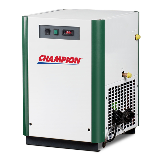
CRN SERIES
Models: CRN25, CRN35, CRN50, CRN75
CONTENTS
GENERAL SAFETY INFORMATION ....................... 2
RECEIVING, MOVING, AND UNPACKING .............. 2
1.0 INSTALLATION .............................................. 3
2.0 OPERATION ................................................... 4
3.0 MAINTENANCE ............................................. 5
SIZING ................................................................. 5
ENGINEERING DATA ........................................... 6
P&I DIAGRAM...................................................... 7
WIRING DIAGRAM ............................................... 8
DIMENSIONS / WEIGHTS ..................................... 9
TROUBLESHOOTING GUIDE ................................. 10
PARTS LIST .......................................................... 11
WARRANTY ......................................................... 12
SERVICE DEPARTMENT: (724) 746-1100
REFRIGERATED
TYPE
COMPRESSED
AIR DRYERS
Advertisement
Table of Contents

Summary of Contents for Champion CRN Series
-
Page 1: Table Of Contents
5004822 Rev. A 2/09 INSTRUCTION MANUAL CRN SERIES Models: CRN25, CRN35, CRN50, CRN75 CONTENTS REFRIGERATED GENERAL SAFETY INFORMATION ....... 2 TYPE RECEIVING, MOVING, AND UNPACKING ....2 1.0 INSTALLATION ..........3 2.0 OPERATION ........... 4 COMPRESSED 3.0 MAINTENANCE ..........5 SIZING .............. -
Page 2: General Safety Information
GENERAL SAFETY INFORMATION RECEIVING, MOVING, AND UNPACKING 1. PRESSuRIzED DEVICES: A. RECEIVING This equipment is a pressure This shipment has been thoroughly checked, packed containing device. and inspected before leaving our plant. It was received in good condition by the carrier and was so •... -
Page 3: Installation
IMPORTANT: 1.2 Mounting READ PRIOR TO STARTING THIS EQUIPMENT Mount the dryer on a level solid surface. Holes are provided in the dryer base to permanently mount the dryer to the 1.0 INSTALLATION floor. 1.1 location A. For typical placement in a compressed air system, see drawing. -
Page 4: Operation
1.4 Electrical connections 2.0 OPERATION A. Dryer is designed to operate on the voltage, phase, 2.1 Minimum/Maximum operating conditions and frequency listed on the serial number tag. B. Install in a receptacle of proper voltage. A. Maximum inlet air pressure: refer to dryer serial number tag NOTE: Refrigeration condensing unit is designed to run continuously and should NOT be wired to cycle on/off with... -
Page 5: Maintenance
3.0 MAINTENANCE SIZING 3.1 Condenser coil To determine the maximum inlet flow capacity of a dryer at various operating conditions, multiply the rated capacity Clean off accumulated dust and dirt monthly or as from Table 1 by the multipliers shown in Table 2. necessary in dirty environments. -
Page 6: Engineering Data
ENGINEERING DATA MODEl CRN25 CRN35 CRN50 CRN75 AIR SySTEM DATA 60 Hz Rated Air Flow at 100°F & 100 psig Inlet, 100°F Ambient (scfm) 50 Hz Rated Air Flow at 95°F & 100 psig Inlet, 77°F Ambient (scfm) Minimum / Maximum Inlet Compressed Air Pressure 30 / 232 psig (2.1 / 16.0 barg) Minimum / Maximum Inlet Compressed Air Temperature 40°... -
Page 7: P&I Diagram
P&I DIAGRAM Models CRN25 through CRN75... -
Page 8: Wiring Diagram
WIRING DIAGRAM Models CRN25 through CRN75... -
Page 9: Dimensions / Weights
DIMENSIONS / WEIGHTS MODEl CRN25 CRN35 CRN50 CRN75 FLOW RATE (SCFM) DIM “A” – AIR I/O CONNECTIONS 1/2" MPT 3/4” MPT WEIGHT, lbs (kg) 86 (39) 90 (41) 95 (43) 106 (48) NOTE: Dimensions and Weights are for reference only. Request certified drawings for construction purposes. 9.13/16 (249) 18 (457) 3.7/16 (87) -
Page 10: Troubleshooting Guide
TROUBLESHOOTING GUIDE SyMPTOM POSSIBlE CAuSE(S) CORRECTIVE ACTION A. Water downstream of 1. Residual free moisture remaining in Blow out system with dry air. dryer. downstream pipelines. 2. Air by-pass system is open. Check valve positions. 3. Inlet and outlet connections are Check for correct connection. -
Page 11: Parts List
PARTS LIST PARTS DESCRIPTION - 115/1/60 CRN25 CRN35 CRN50 CRN75 Condensing Unit G5004703 G5004704 G5004705 G5004706 Compressor G5004855 G5004856 G5004857 G5004858 Start Relay G5004863 G5004864 G5004865 G5004866 Start Capacitor G5004870 G5004871 G5004872 G5004873 Fan Motor G5004876 G5004876 G5004877 G5004876 Fan Blade G5004808 G5004808 G5004879... -
Page 12: Warranty
Phone: 815/875-3321 Fax: 815/872-0421 E-mail: Champion@championpneumatic.com © 2009 Gardner Denver Plants in Princeton, IL, and Manteca, CA Litho in U.S.A. Due to Champion’s continuing product development program,specifications and 5004822 Rev. A 2/09 materials are subject to change without notice or obligation.


Need help?
Do you have a question about the CRN Series and is the answer not in the manual?
Questions and answers
Air is continuously being release out of the system causing multiple issues down the production line.