Table of Contents
Advertisement
Advertisement
Table of Contents

Summary of Contents for Lambretta V125 Special 2018
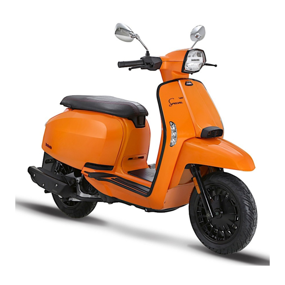
- Page 1 USER MANUAL | ENG mod.# V125 Special...
-
Page 3: Warranty Sheet
Furthermore, I agree to have all repairs and maintenance work carried out only by an authorized Lambretta dealer. Failure to do so, may lead to a loss of warranty. -
Page 5: Introduction
Introduction It is with great pleasure that we can announce that you have joined the family of Lambretta owners. We would like to thank you for the trust you have placed in us. Before you took possession of the Lambretta produced in our factories, it was subjected to countless tests, which allows us to guarantee its quality. -
Page 6: Important Manual Information
Important manual information In this manual, all important informations are distinguished by the following notations: Is a WARNING which has to be followed. Refusing to follow can lead to WARNING severe injury or death to the operator. CAUTION A CAUTION indicates an important information to avoid damage to the vehicle. CAUTION •... - Page 7 Important manual information Dealer label here...
-
Page 8: Table Of Contents
Table of contents Warranty sheet Operation and important riding points Lighting Starting the engine Introduction Troubleshooting Starting off Important manual information Clean and storage Acceleration / Deceleration Clean the vehicle Table of contents Braking Storage Parking Safety information Specifications Engine break in Description of the vehicle Dimensions Periodic maintenance and minor repair 22... -
Page 9: Safety Information
Safety information This Lambretta is a two wheeled vehic- Safe riding: • The posture of the operator and le. Safe driving and good operation de- • Always pre-check your vehicle befo- passenger is important for proper pends on the proper riding technique of re riding to ensure the safety of the control. - Page 10 Safety information protection, and can reduce the de- Be extremely cautious and follow the vehicle before riding gree of injuries from accidents. limitations below when equipped with • Never attach any large or heavy • Never wear loose clothes, otherwi- accessories / cargo.
- Page 11 Safety information • Accessories on the handlebar or • Take care not to spill any gasoline please see your doctor immedia- front suspension area will cause on the engine (hot) or exhaust sys- tely. Keep gasoline away from your bad influence on steering the vehic- tem when refueling.
-
Page 12: Description Of The Vehicle
Description of the vehicle Side view 1. Front disc brake 2. Front wheel 3. Front turn signal light 4. Headlight 5. Rear view mirror 6. Seat 7. Storage compartment 8. Fuel tank cap 9. Rear Carrier 10. Tail/brake light 11. Rear turn signal light 12. -
Page 13: Controls And Instruments
Description of the vehicle Controls and instruments 1. Left handlebar switches 2. Rear brake lever 3. Speedometer unit 4. Right handlebar switches 5. Throttle grip 6. Front brake lever 7. Main switch/steering lock... -
Page 14: Consumer Information
Consumer information Vehicle identification number (VIN) Please write down the VIN (vehicle identification number) to order replacement parts from your dealer or in case the vehicle gets stolen. The VIN is stamped into the frame and located in the glove compartment (1). The engine number is located under the engine near the main stand mount (2). -
Page 15: Instrument And Control Functions
Instrument and control functions Main switch Lock Open the seat: The steering is locked, and all electrical When in position „ “ (Off) , turn the key systems are off. The key can be remo- counterclockwise without pushing it in ved. -
Page 16: Dashboard Unit
Instrument and control functions Dashboard unit appears one by one from top to bottom. 9. Turn signal indicator right If only the last bar remains, it will start 10. Fuel warning indicator to blink, to indicate that there is very 11. -
Page 17: Handlebar Switches - Left
Instrument and control functions Handlebar switches - Left 12. Clock 8. Turn signal indicator left The clock shows the current time. This indicator light flashes when the Set the time: When in ODO mode hold turn signal light is activated. the SET button for 2 seconds to enter the clock setting. -
Page 18: Handlebar Switches - Right
Instrument and control functions Brake lever 3. Horn button 5. Electro start button Push this button to sound the horn. Push this button and pull a brake le- ver to the start the engine. Handlebar switches - Right CAUTION Before starting the vehicle check the operation and important riding points in the user manual. -
Page 19: Fuel Tank Cap
Instrument and control functions Fuel tank cap Fuel Catalytic converter The fuel cap is located under the seat. Make sure that there is sufficient fuel in This model is equipped with a catalytic the tank. Fill the fuel tank to the bottom converter in the exhaust system. -
Page 20: Seat
Instrument and control functions Seat CAUTION CAUTION • When you close the seat by force, Do not exceed the load limit of 10 kg for To open the seat parts can be damaged. the storage luggage box. 1. Place the vehicle on the main stand. •... -
Page 21: Side Stand
Instrument and control functions Side stand Main stand Combined brake system (CBS) The main stand (2) is located under the The CBS (Combined Brake System) is Vehicle. To engage the main stand, use a combined brake system which contri- your foot to step on the bracket of the butes to the road safety support of your main stand and then pull the vehicle on motorcycle. -
Page 22: Pre-Operation Checks
Pre-operation checks The condition of a vehicle is the owner’s responsibility. The operator should check the vehicle by a simple but thorough ins- pection, to make sure of the vehicle´s condition, checking some key and important parts, to prevent the vehicle from serious failure / accident. -
Page 23: Pre-Operation Check List
Pre-operation checks Pre-operation check list Checkpoint To verify Fuel Check fuel level in the fuel tank. Refuel if necessary. Check the fuel line for leakage. Engine / Transmission oil Check oil level. If necessary, add recommended oil to specified level. Check for oil leakage. -
Page 24: Operation And Important Riding Points
Operation and important riding points 2. Sit astride the seat, and then adjust 1. Turn the key to ON WARNING the rear view mirrors. 2. Pull the right brake lever otherwise • Before riding the vehicle, please 3. Switch the turn signal on to the di- the vehicle will not start. -
Page 25: Braking
Operation and important riding points Braking Parking Front When parking, stop the engine, and • Close the throttle completely. then remove the key from the main • Apply both front and rear brakes si- switch. multaneously while gradually incre- asing the pressure. WARNING Since the engine and exhaust system WARNING... -
Page 26: Periodic Maintenance And Minor Repair
Periodic maintenance and minor repair Owner’s tool kit CAUTION CAUTION Most of the Safety and condition of the If you do not have the tools or experi- The owner’s tool kit (1) is located inside vehicle depend on how you do the cor- ence required for a particular job, have the rear storage luggage box. -
Page 27: Battery Cover
Periodic maintenance and minor repair Battery cover Spark plug The spark plug is an important engine component, which is easy to check. Since heat and deposits will cause any spark plug to slowly erode, the spark plug should be removed and checked in accordance with the periodic mainte- nance and lubrication chart. -
Page 28: Engine Oil
Periodic maintenance and minor repair 2. Open the main stand, and take out WARNING the oil level gauge (1) to clean it. Spark plug gap: 0,6 - 0,7 mm Please note that no other spark plug 3. Reinsert oil level gauge (1), don’t model is allowed. -
Page 29: Final Transmission Oil
Periodic maintenance and minor repair Change the final transmission oil Engine Oil capacity: 1. Start the engine, warm up the final Tightening torque: 10-15 Nm 0,7 l at oil change transmission oil by riding the ve- hicle for several minutes, and then Viscosity: 10W-30 stop the engine. -
Page 30: Air Filter
Periodic maintenance and minor repair Air filter Throttle cable free play 6. Install the air filter case cover by in- stalling the screws. CAUTION • Make sure that the air filter element is properly seated in the air filter case. •... - Page 31 Periodic maintenance and minor repair Tire air pressure sign, and may cause damge or even Tire inspection The tire air pressure should be checked lead to an accident. and, if necessary, adjusted before each Allocation of your cargo and weight of ride.
-
Page 32: Rims
Periodic maintenance and minor repair cracked wheel must be replaced. CAUTION Dimensions tires / rims • The wheel should be balanced whe- The tread depth may vary depending on never either the tire or wheel has country. Observe local regulations. The Front been changed or replaced. -
Page 33: Brake Pads
Periodic maintenance and minor repair motorcycle. Air in the hydraulic system dicator almost touches the brake disc. and the brake system for leakage. will diminish the braking performance, In this case have a dealer replace the • When checking the fluid level, make which may result in loss of control and brake pads as a set. -
Page 34: Cables
Periodic maintenance and minor repair surfaces or plastic parts. Always Front brake lever WARNING clean up spilled fluid immediately. Damage to the outer housing of cables • As the brake pads wear, it is normal may result in internal rusting and cause for the brake fluid level to gradually interference with cable movement. -
Page 35: Main Stand / Side Stand
Periodic maintenance and minor repair Main stand / Side stand Front fork CAUTION The condition and operation of the front The operation of the main (1) and side fork must be checked as follows at the (2) stand should be checked before intervals specified in the periodic main- each ride, and the pivots and metal-to- tenance and lubrication chart. -
Page 36: Steering
Periodic maintenance and minor repair Steering Battery This model is equipped with a mainte- WARNING Worn or loose steering bearings may nance free battery. There is no need to cause danger. Therefore, the operati- check the electrolyte or to add distilled on of the steering must be checked as water. -
Page 37: Fuses
Periodic maintenance and minor repair • Batteries develop explosive hy- • Fully charge the battery before ins- then the positive cable. drogen gas. Keep open flames, tallation. Fuses smoking materials away from • After installation, make sure that the battery and make sure there the battery cables are properly con- is adequate ventilation when you nected to the battery terminals. -
Page 38: Lighting
Periodic maintenance and minor repair Lighting Specified fuses: 10, 15, 20 A All lights on this vehicle are equipped with LED. If a light is damaged, contact your dealer to replace it. WARNING Do not use a fuse of a higher amperage Headlight adjustment rating than recommended to avoid causing extensive damage to the elec-... -
Page 39: Troubleshooting
Troubleshooting Although all our Lambrettas receive a thorough inspection before the shipment from the factory, trouble may occur during operation. Any problem in the fuel, compression, or ignition system, for example, can cause poor starting ability and loss of power. The following troubleshooting chart represents a quick and easy procedure for checking these vital systems by yourself. - Page 40 Troubleshooting Troubleshooting chart Failure Cause To Do Wire harness is worn Check the wiring harness Contact problem in a plug Check the plugs of the wiring harness Engine turns but does not start or stalls No gasoline in the tank Refill gasoline Problem with the fuel pump Check the fuel pump...
-
Page 41: Clean And Storage
Clean and storage Clean the vehicle to the sensitive components of the Cleaning after riding in the rain, near vehicle to prevent damage. Dry the the sea or on salt-sprayed roads plastic parts with a soft, dry cloth or Cleaning the vehicle in a proper and sui- sponge. -
Page 42: Storage
Clean and storage Long-term (for weeks) • Check and correct the tire pres- WARNING • Clean the vehicle. sure and lift the vehicle, so that • Make sure that there is no oil or • Fill the fuel tank up completely or neither of the two wheels is on wax on the brakes or tires. -
Page 43: Specifications
Specifications Dimensions 1340 1890 1340 1890... - Page 44 Specifications Engine Type 4-stroke, forced air cooled Manufacturer SYNERJECT Cylinder arrangement Single cylinder Spark plug Displacement 124,6 cm3 Manufacturer Compression ratio 10,7:1 Type CR7HSA Starting system Electric starter Spark plug gap 0,6 - 0,7 mm Lubrication system Wet sump lubrication Clutch Engine oil Clutch type...
- Page 45 Specifications Brake system Electric system Front brake Ignition system Type Single Hydraulic disc brake Charging system ECU Magneto Size 226mm Battery Operation Right hand / Left hand (CBS) Voltage, capacity 12 V, 6 Ah Rear brake USB connector 5V 2A Type Single Hydraulic disc brake Lamps...
-
Page 46: Warranty Information
Warranty information Please carefully read the instruction manual of your vehicle before operating it in order to make yourself familiar with its handling. We explicitly point out that the instruction, maintenance, and care instructions given in the operating manual have to be complied with in order to sustain your claim towards warranty. -
Page 47: Service And Maintenance
Service and maintenance Important information The date for the implementation of maintenance depends on whichever limit is reached first. That means either the driven kilometers or the duration from initial startup. The warranty can be granted only when the vehicle is serviced in accordance with this plan and was not exposed to extraor- dinary stress. -
Page 48: Maintenance Schedule
Service and maintenance Maintenance schedule 4000km or 7000km or 10000km or 13000km or 1000km The inspection intervals are required, these will void the warranty. 1. year 2. year 3. year 4. year Component Perform Airfilter Clean/ Exchange Exchange ... -
Page 49: Service Record
Service and maintenance Service record In the delivery of the vehicle the customer data and vehicle data must be supplemented. Maintenance interval: Delivery inspection Maintenance interval: 1000 km Maintenance interval: 4000 km or 1. year Odometer reading: Odometer reading: Current odometer reading: Date: Date: Date:... -
Page 51: Space For Notes
Space for notes... - Page 53 The copyright is owned by Copyright © 2018 Distributed by: the Company / Manufacturer: All rights reserved. KSR Group GmbH Lambretta GmbH This user manual is copyrighted. Im Wirtschaftspark 15 Im Wirtschaftspark 15 Copying in mechanical, electronic or any 3494 Gedersdorf...
Need help?
Do you have a question about the V125 Special 2018 and is the answer not in the manual?
Questions and answers