Advertisement
Quick Links
Advertisement

Summary of Contents for Aesus AESFill AF1
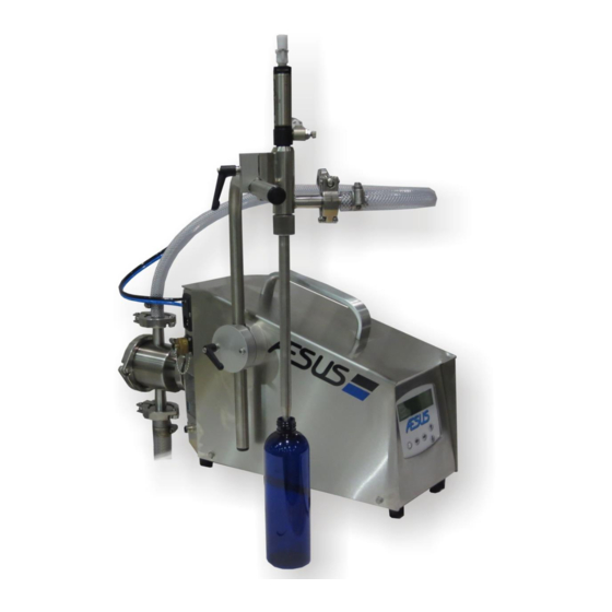
- Page 1 Owner’s Manual AESFill AF1 Single headgear pump filling machine **Note—Machine image may not be the same as what was purchased. Edition Date: 2018-09-04 Aesus Packaging Systems www.aesus.com 188 Oneida Drive Pointe-Claire Montréal, Quebec Canada H9R 1A8 (514) 694-3439 Fax (514) 694-4107...
-
Page 2: Notice Regarding Osha Regulations
Sellers shall not be responsible for designs or instructions furnished by the buyer or his agents. Seller makes no warranties with respect to noise and will not be responsible for any fines, penalties, or consequential damages. Aesus Packaging Systems Pointe-Claire (Montréal), Québec Canada... -
Page 3: Table Of Contents
Disclaimer and Limitation of Liability ..............................9 Installation ..................................10 Unpacking the Machine ................................10 Installing the Machine ................................10 2.2.1 Front of AESFill AF1 ................................. 10 2.2.2 Rear of AESFill AF1 ................................10 General Description ..............................12 AESPump ..................................13 To assemble the pump ................................ -
Page 4: Table Of Contents
Access continuous pumping ..............................31 Nozzle only ..................................... 32 Continuous pumping ................................32 7.10 Open spout ..................................... 32 7.11 Close spout ..................................... 32 7.12 Gating (Optional) ..................................33 7.12.1 Gap timer ..................................33 7.12.2 Gating delay ..................................33 7.12.3 Start eye delay ................................33 7.13 Dive (Optional) .................................. -
Page 5: Table Of Contents
Pneumatic Controls for Shut-Off Nozzles ..........................54 15. Recommended Spare Parts ............................55 16. Contact Information ..............................57 17. Some of the other Machinery Manufactured by Aesus Packaging Systems ..............58 List of Appendix Appendix 1: Assembly Drawings ..............................Apdx 1 Appendix 2: Electrical Drawings ................................ -
Page 6: Table Of Contents
Figure 4-7: Pump Assembly 5 ................................... 14 Figure 4-8: Pump Assembly 6 ................................... 15 Figure 4-9: Pump Assembly 7 ................................... 15 Figure 4-10: Standard Nozzle Assembly ..............................16 Figure 4-11: 1 ½“Nozzle ................................... 17 Figure 4-12: 1 ½“Custom Nozzle Assembly .............................. 17 Figure 4-13: Position of the equipment .............................. -
Page 7: Table Of Contents
Figure 7-18: Dive Screen ..................................34 Figure 7-19: Neck dive Screen .................................. 34 Figure 7-20: Bottom Delay Screen ................................34 Figure 7-21: Neck Clam Screen ................................34 Figure 7-22: Full-dive Screen ..................................35 Figure 7-23: Bottom Delay Screen ................................35 Figure 7-24: Neck Delay Screen ................................ -
Page 8: Warranty & Terms And Conditions Of Sale
An ”Aesus in attendance” run is a test of a duration that is acceptable to both Aesus and the customer (at suitable charges) at an Aesus facility or at the customer’s facility, with qualified Aesus engineer(s) in attendance for the purpose of qualifying and accepting the machine (FAT). -
Page 9: Disclaimer And Limitation Of Liability
Aesus or their representatives. WAIVER: Our failure to insist upon any of these terms and conditions shall not be deemed a waiver of any rights that Aesus may have, and shall not be deemed a waiver of any subsequent breach or default in these terms and conditions. -
Page 10: Installation
Front of AESFill AF1 The AESFill Body consists of one stainless steel encased unit. This body houses the drive of the AESFill AF1, which is an AC Inverter system with an exclusive frequency speed control. The machine is supplied to match your voltage but is convertible from 110/60/1 to 220/50–60/1. -
Page 11: Figure 2-3: Rear Of Aesfill Af1
Exhaust Muffler Power Chord Plug Black & Blue Nozzle air On/Off Switch connections 19 Pin Rating Plate Communication Cable Port Air Regulator 5 Pin AESPump Communication Cable Port Figure 2-3: Rear of AESFill AF1 11/58 General Description AESFill AF1C Machine Manual... -
Page 12: General Description
AESFill automatic fillers. If you find that manual filling using the AESFill AF1 fillers is too slow, you can add the automation package and the system can be automated over any conveyor. There are different options that can be added for different types of products such as neck dive for cleaner filling or full dive for foamy products. -
Page 13: Aespump
4. AESPump The AESPump consists of 17 pieces: 1. 1 Face Plate 2. 1 O-Ring BunaN (Other materials available) 3. 1 Pump Body 4. 2 Tri-Clover Sanitary Clamps (1–3” Dia. & 1–2” Dia.) 5. 2 Gears 6. 1 Stainless Steel Drive Shaft (4 1/8”, 10.5 cm) 7. -
Page 14: To Assemble The Pump
To assemble the pump Figure 4-2: Pump Assembly 1. If removed, replace the U-cup drive shaft seal by Figure 4-5: Pump Assembly 3 inserting the small diameter edge of the seal back into the drive shaft hole recess. Slide both gears onto the shafts making sure that they locate on the hexagonal sections of the shafts. -
Page 15: Figure 4-8: Pump Assembly 6
AESFill AF1. Place the AESPump on top of the docking plate and use the sanitary clamp to fasten the two pieces together. No sealing... -
Page 16: Nozzle
Nozzle 4.2.1 Standard Nozzles The nozzle consists of 11 pieces: 2–90 Degree Quick Connect Air 1. 1 Quick Connect Air Fitting Fitting 2. 1 90 degree Quick Connect Air Fitting 3. 1 Air Tubing Duo (Black and Blue) 1- Quick Connect 4. -
Page 17: Custom Nozzles
4.2.3 Custom Nozzles The 1 ½“nozzle is comprised of 14 parts. Quick Connect air fitting (Part EDT-75630) Adjustable Handle (Part EDT-88039) Tri-clover Seal (Part EDT-91105B) Tri-clover clamp (Part FIL333) Flow Control (Part FIL66984) Stem Top O ring (Part FIL85948) Stem bottom O ring (Part FIL85949) Spout O ring (Part FIL85955) 100. -
Page 18: Positioning The Equipment
Height Adjustments You can raise and lower the nozzle bar attached to the AESFill AF1, so that the nozzle is at the appropriate height for the bottles that you are filling by loosening the black ratchet handle and sliding the nozzle bar up or down. -
Page 19: Connections
The main power inlet is located at the back of the machine. Depending on your requirements, the machine has been configured to handle either 110 V or 220 V, 50/60 Hz. Check the rating plate to see if it matches your supply. If it does not, call Aesus. -
Page 20: Air Supply & Lubrication
Air Supply & Lubrication On the back of the machine there is a filter regulator. The filter cleans the air, the regulator controls the outlet pressure. The air valve solenoid inside the cabinet controls the air going to the air cylinder. At the appropriate time, when the nozzle needs to be opened or closed, the air is directed out of one connection or the other. -
Page 21: Quick Setup
5. Quick Setup Quick Setup in 5 Easy Steps 5.1.1 Nozzle 5.1.2 Pump Attach the nozzle to the nozzle bar. Using the triclover fittings, attach the hoses to the pump. You Attach the black air hose can identify the inlet and outlet fittings of the pump using the from the black tagged fitting arrow engraved on the back face of the pump. -
Page 22: Foot Switch
5.1.3 Foot switch Quick & Easy Priming Plug the foot switch cable into the matching connector on the 1. Take both air hoses off the nozzle, and attach the AF1. Plug the machine into a source of 117 VAC. Power up the black pressure hose to the side of the nozzle and the machine via the rocker switch located on the rear panel of blue hose to the top in order... -
Page 23: Setup For Machine With Conveyor And Gate Indexing System
6. Setup for Machine with Conveyor and Gate Indexing System **NOTE: The image contain up to 12 nuzzle and pump, but the setup steps are the same if the machine contains 1 or 12 pumps. Neck Clamps (Optional) The AESFill machine is equipped with neck clamps that allow each bottle to be perfectly placed and held in place during the filling. -
Page 24: Nozzle Barre Adjustment
Nozzle Barre Adjustment The nozzle barre is used to attach the nozzle. This barre will move automatically in synch with the gating system, but the general height of the barre needs to be manually adjusted to fit the size of the bottle to fill. Black crank Figure 6-4: Neck clamps Sideway adjustment 3 Orange Ratchet... -
Page 25: Guide Rails Adjustments
Guide rails adjustments The AESFill comes with a conveyor to get the bottle to the filling machine. For each different size of bottle the guide rails need to be correctly adjusted. Each guard rail will need to be adjusted in height and in the IN/OUT position. -
Page 26: Gates Adjustments
**NOTE: The pictures included in this section may not be exactly the same as your machine depending on your configuration. Height Adjustment Gates adjustments This filling machine is equipped with a set of gates to control the infeed of bottles under the nozzles and also allow the right amount of bottle to be filled at the same time. -
Page 27: St Container Sensor
1st Container Sensor Please note that depending on your container type and your machine, the exact type of sensor may differ. Figure 6-14: Outfeed gate adjustment Adjust the 1 container sensor 1” back from the Figure 6-16: Outfeed gate adjustment container, below the neck. -
Page 28: Gap Sensor
Gap Sensor Backup Sensor Gap Sensor Flow Direction 1 to 2 container diameters apart Figure 6-17: Outfeed gate adjustment vi. The gap sensor should be located 1 to 2 container diameters downstream from the outfeed gate. Backup Sensor Figure 6-19: Outfeed gate adjustment ix. -
Page 29: Pump Screens
7. Pump Screens Below, shows the screen hierarchy for the AF1C. To access and scroll through the settings press the menu key repeatedly. When extra options are available for that setting, press the marked arrow to access the extra options. Use the Up/Down arrows to change the feature’s setting. -
Page 30: Home Screen / Run Screen
Home screen / Run screen Fill Setting Figure 7-2: Home Screen Figure 7-4: Fill Screen Use left and right keys to change digits, up and down keys to change setting. Keep fingers pressed for rapid action. Change is instantaneous. Press the Menu key to access more Settings Figure 7-3: Run Screen Speed You see the programmed fill volume and the set filling speed. -
Page 31: Repeat Fill
Repeat Fill Slave Figure 7-6: Repeat Fill Screen Use up and down arrows to adjust the time delay between fills in semi-automatic mode. Setting to “0” turns off semi- automatic mode. Keep fingers pressed for rapid action. Change will affect the next delay. Press the Menu key to access more Settings Figure 7-8: Slave Screen Go to Special Settings... -
Page 32: Nozzle Only
Nozzle only 7.10 Open spout Figure 7-12: Spout Use the up and down arrow keys to adjust a pre-opening delay to allow the nozzle to be fully open before starting the pump. For most liquids, a setting of 1/10 seconds is desired. Keep fingers pressed... -
Page 33: Gating (Optional)
7.12 Gating (Optional) 7.12.2 Gating delay Figure 7-14: Gating Screen Use the up and down arrow keys to toggle on and off the Figure 7-16: Gating Delay Screen gating functions. When networking units together, use this setting only on the master unit. When gating is set to ON and Use the up and down arrow keys to adjust the gating delay. -
Page 34: Dive (Optional)
7.13 Dive (Optional) 7.13.2 Bottom delay Figure 7-18: Dive Screen Use the up and down arrow keys to switch the function from Off to ON in sequence. Figure 7-20: Bottom Delay Screen When the dive is set to ON settings and timers for the dive Use the up and down arrow keys to adjust the bottom delay function are made available through the right arrow key. -
Page 35: Full Dive
7.13.4 Full Dive speed of the pump, changing the pump speed will adjust the bottom delay time as well. If full dive is selected press the arrow to the right key to access other full-dive related settings. Press the arrow to the left key to go back to the Neck / Full- dive screen. -
Page 36: Container Height
Press the arrow to the right key to access more dive related 7.13.9 Neck clearance settings. Press the arrow to the left key to go back to the neck delay screen. 7.13.8 Container height Figure 7-27: Neck Clearance Screen Use the up and down arrow keys to adjust the travel of the nozzle bar to clear the neck and let the containers exit the filling area. -
Page 37: Profile Filling
7.14 Profile Filling 7.14.2 Slow start duration Figure 7-28: Profile Filling Screen Use the up and down arrow keys to toggle the profile filling function on and off. When the profile filling is set to on, you Figure 7-30: Slow start Screen can access the profile filling settings by pressing the arrow to the right key. -
Page 38: Slow End Duration
Press the arrow to the left key to go back to the Slow start Press the arrow to the left key to go back to the Pump speed duration screen. at the end screen. 7.15 Return to RUN SCREEN 7.14.4 Slow end duration Figure 7-33: Return Screen Figure 7-32: Slow end Screen... -
Page 39: Af1 Remote Screens (Optional)
8. AF1 Remote Screens (OPTIONAL) 8.1.1 Remote Screen Aesus Logo: To open the configuration menu (). The remote screen can be placed anywhere on the frame of the machine. : Monitor the lifting system’s position Alarms: To open the Alarms page (). -
Page 40: Alarms Screen
Neck Clamp: This enables or disables the neck clamp from running in the filling sequence. If you do not need a neck clamp, you can turn it off or on as necessary. Indexing System: This enables or disables the indexing system from working during the filling sequence. -
Page 41: Gating Setup Screen (Optional)
8.1.5 Gating Setup Screen (Optional) 8.1.6.1 Pump 1 Setup Screen Figure 8-8: Gating Setup Screen (Optional) Figure 8-10: Pump 1 Setup Screen 1— Start eye delay: Delay before the machine acknowledges Pre-Open Delay (ms): This is the time delay between the container presence or starts diving while the start eye is opening of the nozzles, and the pumps beginning to rotate. -
Page 42: Pump 2 Setup Screen (Optional)
8.1.6.2 Pump 2 Setup Screen (Optional) 8.1.6.3 Pump 3 Setup Screen (Optional) Figure 8-11: Pump 2 Setup Screen Figure 8-12: Pump 3 Setup Screen Pre-Open Delay (ms): This is the time delay between the Pre-Open Delay (ms): This is the time delay between the opening of the nozzles, and the pumps beginning to rotate. -
Page 43: Pump 4 Setup Screen (Optional)
8.1.6.4 Pump 4 Setup Screen (Optional) 8.1.7 Pump 1 Profile Filling Setup Screen This screen allows the setting of different pumping speed for one dispense. Example if you want to start fast and finish filling more slowly. If you change the set speed or volume, these settings will adjust accordingly. -
Page 44: Pump 3 Profile Filling Setup Screen (Optional)
ON/OFF: Enables or disables the profile filling for pump 2. 8.1.7.3 Pump 4 Profile Filling Setup Screen (Optional) Start Speed (%): This represents a % of the pump set speed for the beginning of the dispense process for pump 2. Duration (%): This represents a % of the full-filling volume for which you want to keep the start speed for pump 2. -
Page 45: Test Screen
The remaining 10% of the volume will be dispensed during the travelling of the nozzle of the last 55% of the container neck height (long thin neck). 8.1.9 Test Screen Figure 8-18: Profile Lifting Setup Screen Step 3: Is always 100% of volume at 100% neck height. Step 2: Settings are always equal to or greater than step 1. -
Page 46: Feed Tanks
You may have requested a feed tank be supplied with your AESFill AF1 unit(s). If you have multiple fillers, the feed tank should have multiple outlets on the bottom. Each AESFill AF1 should be attached to its own outlet at the bottom of the tank. Do not attach more than one pump to an individual outlet, as this can cause pump starvation, leading to inaccurate filling, and possible pump damage. -
Page 47: Nozzle Types
10. Nozzle Types The standard nozzle supplied with the AESFill AF1 is a No-Drip Nozzle, which is available in several standard diameters, and can be customized to meet your special needs. These nozzles have an air cylinder operated by an air solenoid requiring compressed air. -
Page 48: Exchanging Nozzles & Pumps
If the product is very viscous or needs a solvent in order to effect cleaning, the solvent can be run through the AESFill AF1 in order to begin the cleaning process. (Based on compatibility with the elastomeric seals.) 10.2... -
Page 49: Changeover
Simple Changeover The simple changeover is called simple, because it is just that. The only hitch in the process is that you need a second complete pump/nozzle assembly for each AESFill AF1 machine. Turn off the AESFill AF1 machine. Disconnect the air hoses from the nozzle. -
Page 50: Networking Multiple Af1S Together
12. Networking Multiple AF1s Together AF1s are wonderful stand-alone units for liquid filling but once production increases you may need to add more fillers together in order to fill faster. The AF1 is equipped with the ability to network together so that the start signal will start all of the AF1s that are networked at the same time. -
Page 51: Troubleshooting
13. Troubleshooting 13.1 General Troubleshooting **REMOVE POWER BEFORE PERFORMING ANY SERVICE** Table 2: Troubleshooting and quick solutions Fault Reason Remedy Check fuse in your supply line and in the machine. Machine will not start. It should be a 3 AG type, 10 amp slow blow for Fuse blown 110 volts supplied. -
Page 52: Inconsistent Fills
Warm liquid. Difficult liquid. Liquid too viscous Use overhead hopper. Attach the air hoses from the AESFill AF1 to the Air Nozzle stem plunger not moving Air hoses not attached to air fast enough. cylinders. -
Page 53: Dripping Nozzle
13.3 Dripping Nozzle **REMOVE POWER BEFORE PERFORMING ANY SERVICE** Table 4: Troubleshooting and quick solution 3 Cause Reason Remedy Be sure that suction hose is always completely Air entering pumping systems. Hose has come out of products in supply tanks. Supply tank is submerged. -
Page 54: General Maintenance
14. General Maintenance This is intended as a guide only. Actual maintenance intervals and service schedule will depend upon conditions of use. Product properties, production environment, quality of compressed air and other variables may contribute to establishing a suitable preventive maintenance schedule. 14.1 Before Each Production Run ... -
Page 55: Recommended Spare Parts
15. Recommended Spare Parts Please contact our spare parts department for an exact list of recommended spare parts for your specific machine: Tel. 514-694-3439 parts@aesus.com. Table 5: Recommended spare parts Item # Part Description Electrical 31066 10 A Slow Blow Fuse—110 V Machines 44003 5 A Slow Blow Fuse—220 V Machines... - Page 56 ELE1230 6 AMP FUSE ATMR ELE1232 8 AMP FUSE ATMR 56/58 Recommended Spare Parts AESFill AF1C Machine Manual...
-
Page 57: Contact Information
16. Contact Information For Spare Parts or Technical Help please contact us, quoting the machine serial number: Aesus Packaging Systems, Inc. 188 Oneida Drive Pointe-Claire, Québec H9R 1A8 Canada 514-694-3439 Fax: 514-694-4107 contactus@aesus.com www.aesus.com 57/58 AESFill AF1C Machine Manual Contact Information... -
Page 58: Some Of The Other Machinery Manufactured By Aesus Packaging Systems
17. Some of the other Machinery Manufactured by Aesus Packaging Systems Some other Machines Manufactured by Aesus See the rest at www.aesus.com Wrap and Panel Labellers Top and Bottom Labellers Single Spindle Cappers Retorquers Print and Apply Labellers Neck Banders...
Need help?
Do you have a question about the AESFill AF1 and is the answer not in the manual?
Questions and answers