Table of Contents
Advertisement
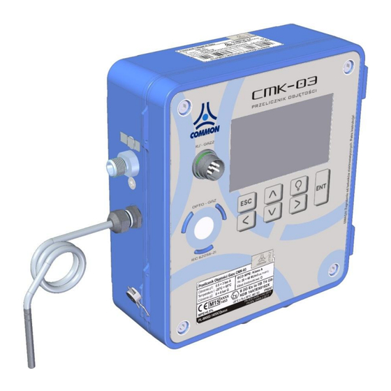
CMK-03 GAS VOLUME CONVERTER
OPERATING INSTRUCTION
Edition: CMK3 / 102U
Firmware version: 2.2.39-39-2.7.8
Lodz, June 2016
Technical specification and construction may change due to improvement. This publication serves as general information only, and all specifi-
cations are subject to confirmation by COMMON S.A.
Advertisement
Table of Contents

Summary of Contents for Common CMK-03
- Page 1 CMK-03 GAS VOLUME CONVERTER OPERATING INSTRUCTION Edition: CMK3 / 102U Firmware version: 2.2.39-39-2.7.8 Lodz, June 2016 Technical specification and construction may change due to improvement. This publication serves as general information only, and all specifi- cations are subject to confirmation by COMMON S.A.
-
Page 2: Table Of Contents
Connection the external pressure CPC-03 converter 5.6.1 Mechanical installation 5.6.2 Electrical connection of CPC-03 Connecting the LF input to the gas meter Mechanical installation of the CMK-03 — appendix 1 Battery 5.9.1 Main battery 5.9.2 Battery of LCD backlight 5.10... - Page 3 12.3 12.4 LCD power supply 12.5 Reserve1 configuration in GAZ-MODEM 12.6 Activity time of OPTO-GAZ port REMOTE CONTROL OF CMK-03, USERS, AUTHORIZATION 13.1 CCTool configurator 13.1.1 Connection by using COGUSB-03 13.1.2 Users and authorization DATA REGISTRATION, READING AND CONFIRGURATION IN TELEMETRIC SYSTEMS 14.1...
- Page 4 COMMON S.A. OPERATING INSTRUCTION CMK-03 14.1.2 Events 14.2 Reading and configuration in the telemetric systems ENVIRONMENTAL PROTECTION 15.1 Packaging waste 15.2 Disposal of used batteries and devices after life-time HISTORY OF THE DOCUMENTATION CHANGES NOTES...
-
Page 5: Introduction
2.2 Storage The elements of the CMK-03 should be storage in the original package in room with temperature from -20°C till +60°C and humidity which does not exceeding 80%, without vapour and chemically active compounds. -
Page 6: Warranty Repairs
The CMK-03 should be disassembled from the operating point in case of doubt regarding the correctness of instrument indications. The device should be pass to the appropriate laboratory for checking and verification. The checking may be carried out by means of control instruments without damage or removing the manufacturer's protection seals. - Page 7 COMMON S.A. OPERATING INSTRUCTION CMK-03 Assembly set: O-Type, flat handles Part name Quantity O-Type, flat handle bolt (cylinder type) M5x40 bolt (cylinder type) M5x12 washer M5 nut M5 see part 5.8.2 Assembly set: L-Type, flat handles, the replacement of the CMK-02...
- Page 8 The CPC-03 Pressure Converter The selected information about converter are described in the Table 4.5 — “The measuring converters of the CMK-03". The detailed information are contained in the service manual and the technical documentation of this device — available on the web site: www.common.pl...
-
Page 9: Construction
6 years. The CMK-03 is a volume converter of the gas Type 1. This is complete measurement system, equipped in the pressure converters, the temperature converters, the input of pulses/volume of the meter and the algorithms for converting the measured volume of gas to the basic conditions. -
Page 10: Technical Data , Conditions Of Usage, Measurement Inputs
OPERATING INSTRUCTION CMK-03 The CMK-03 is equipped in the LCD display with graphical-text menu. The LCD is readable in the entire tempera- ture range. The display backlight is supported by the additional battery which is independent of the converter main battery. - Page 11 The spare parts list PART DESCRIPTION: TYPE: EXAMPLE DRAWING Main battery BAT-03 manufactured by COMMON S.A. SL-760 Xtra manufactured by LCD backlight battery Tadiran Table 4.3 The examples of the CMK-03 available variants EXAMPLES OF THE CMK-03 VARIANTS CMK-03/x/12/-/-/0512/…. CMK-03/x/12/x/12/0512/…. CMK-03/x/e12/x/12/0512/….
- Page 12 COMMON S.A. OPERATING INSTRUCTION CMK-03 Technical parameters Table 4.4 The technical parameters MARKINGS meteorological markings and MID certifi- cate number 1450 PL-MI002-1450CQ0001 Explosion proof construction II 2G Ex ia IIB T4 Gb markings and ATEX certificate number 1453 KDB 14ATEX0102X...
- Page 13 Cable length – 2,5m. connection with CMK-03 volume con- verter POWER SUPPLY 2 sets of battery type: BAT-03 manufactured by COMMON S.A. (execution KOD(7)=S). main internal life time of battery set – minimum 5 years in typical operating conditions (detailed information –...
- Page 14 OUT2 – frequency output proportional to the selected parameter OUT4. OUT3 – representation of the LF input signal OUT3 – representation of the HF input signal ENC INPUTS The input compatible with the CWSL–N Type Encoder digital encoder manufactured by COMMON S.A.
- Page 15 There is a dual input dedicated to the connection for maximum two of the external CPC-03 digital pressure converters. The input assures the power supply for P3 and P4 converters and digital data transmission to the CMK-03 (also in the bat- tery supply working mode).
- Page 16 COMMON S.A. OPERATING INSTRUCTION CMK-03 Compressibility coefficient – the calculating methods Table 4.10 CALCULATING METHODS FOR COMPRESSIBILITY COEFFICIENT APPLICATION RANGE (extended) UNIT 0,5 3; 0,9 6; 2,5 17 bar abs -23,15 +65 °C 6 40; 10 70 bar abs -10 ...
-
Page 17: Intrinsically Safe Parameters
WARNING! Hazard of the electrostatic charges. The front cover of the CMK-03 (elevation, keyboard, display window) is a large surface made of plastic where the electrostatic charges can be accumulated. To avoid electrify effect and danger of discharge this surface can not be rubbed with dry materials! The intrinsically safe parameters are determinate during the analysis of the device structure. - Page 18 COMMON S.A. OPERATING INSTRUCTION CMK-03 ters. The conformity conditions of the intrinsically safe parameters for the connected devices are presented in the Table 4.12. Table 4.12 The conformity conditions of the intrinsically safe parameters CONFORMITY CONDITIONSOF THE INTRINSICALLY SAFE PARAMETERS...
-
Page 19: Assembly And Installation
Assembly and installation It is absolutely necessary to follow the recommendations of this operating instruction by the installation and connection of the CMK-03. The device should be used according to the regulation and rules concerning anti- explosion safety. The CMK-03 can be installed and operate in explosion hazard zone 1 or 2. The device can cooperate with the intrinsically safe circuits on the security level “ia”... -
Page 20: Tuchel Port
COM1 port. The pins designation is described in Figure 5.2. It is recommended to used CZAK-03 barrier to connect the power supply to the CMK-03. The CZAK-03 is manu- factured by COMMON S.A. (see Table 2.1 Additional Accessories). -
Page 21: Internal Clamps
WARNING! It is obligatory to connect correctly the intrinsically safe circuits of the device. It is not allowed to connect to the CMK-03 clamps any external devices with undefined pur- pose. For example: the connection between the output of external power supply (V+,GDN,A,B) with the ExtCPC output of the CPC-03 external converter may occurs permanent device damage and loss of intrinsically safe parameters. -
Page 22: Cables For Intrinsically Safe Circuits
The all cable glands are in EMC execution and are adjusted to connection of the cable shields in their entering place. In the CMK-03 there are two types of the cable glands: M12 and M16 — a ranges of the cable glands diameter are listed in the Table below. - Page 23 COMMON S.A. OPERATING INSTRUCTION CMK-03 DIAMETER OF THE CABLE GLANDS 4,5 6mm 6,5 8mm cable gland cable gland 4x M12 3x M16 Figure.5.4 The cables entering to the housing, the dimensions of cable glands M12, M16 The unused cable glands should be covered by using a cylindrical elements which are made from the hard or elastic material with the proper dimension.
- Page 24 T and P and active transmission on one of the COM ports full load means that CMK-03 is operating with the active options mentioned above and additionally with the activated read function from the Encoder and from the two external CPC-03 converters (connected to the extCPC port).
- Page 25 WARNING! The cable shields should be connected to the CMK-03 housing only on the grounded side by using the cable glands. The shielded cables can not create loops, closing points with different potentials, where could be flow equalizing currents.
- Page 26 2. Ground clamp connection The CMK-03 effective ground connection can be assure by using the ground clamp, which is located on the side of housing. There can be connected a single wire or multi-wire cable with cross-section up to 4mm.
-
Page 27: Connecting The Temperature Sensor
The thermometer serial number is recorded in the CMK-03 memory on the production phase and it is displayed on the LCD screen. The thermometer is formal combined and identified with model of CMK-03. - Page 28 Figure 5.8 Thermometer assembly in piping The Figure 5.9 presents the thermometer placement in the body of gas meter. Figure 5.9 The PT1000 thermo probes assembled in the body of CGT-02 Turbine Gas Meter manufactured by COMMON S.A.
-
Page 29: Common S.a. Operating Instruction Cmk
5.5 Connection of the P1 and P2 pressure sensors The CMK-03 has maximum two built-in pressure converters (P1 and P2 in the Figure 5.10). The connection pipe of the converter has a threat M12x1,5 in the typical application. The available variants and the pressure ranges are listed in the Table 4.5. -
Page 30: Connection The External Pressure Cpc-03 Converter
Connection of the external CPC-03 pressure converter The CMK-03 allows for a reading and registration of the pressure values from two CPC-03 external, digital con- verters manufactured by COMMON S.A. (Table 2.1. Additional Accessories). The technical data of the CPC-03 converter are available in the operating instruction. -
Page 31: Connecting The Lf Input To The Gas Meter
The connections between the converter port and converter clamps are presented in the Figure 5.14. Figure 5.14 The connections of the CPC-03 pressure sensor to the CMK-03 converter clamps . The clamps of the ExtCPC ports are doubled in the both terminal strips. This allows for easy, parallel connection for two cables to the electrical same ExtCPC port. -
Page 32: Mechanical Installation Of The Cmk-03 - Appendix
LFc+ LFc — the input of the LFc pulses from the gas meter index head (e.g. second, control LF transmitter) Mechanical installation of the CMK-03 The installation methods are described in the Appendix 1 – “The mechanical installation methods of the CMK-03”. 5.9 Battery WARNING! It is necessary to use the batteries according to the operating instruction. -
Page 33: Battery Of Lcd Backlight
The CMK-03 calculates in the real time a level of the battery usage. If the estimated battery working life time reaches the level lower than 10%, it will be registered an alerts in the bases: “Archive”, “MID Alarms”, and “Events”. - Page 34 Gas volume conversion Principle of the operation The CMK-03 converter sums the gas volume based on the LF pulses in measuring conditions Vm and also makes conversion of the gas to the basic conditions Vb based on: measured value of the absolute gas pressure p1, ...
- Page 35 COMMON S.A. OPERATING INSTRUCTION CMK-03 – volume counter value in the previous state. mpop The calculations of proper parameters in basic conditions are made in case of: changing the gas composition/parameters changing the reference temperature Tb changing the reference pressure pb ...
-
Page 36: Algorithms
For the “K1=const” method there is no necessary to define the gas composition. The K1 coefficient is equal with the Z/Zb ratio. The conception of this method is to use the CMK-03 on a bio-gas station or others stations where the gas components exceed applicability ranges of the implemented calculating methods in the converter, and operating pressure does not exceed determinate value. -
Page 37: Bio-Gas Configuration
Bio gas configuration AGA8 or SGERG-88 ( The CMK-03 converter is a MID device. The algorithms such as approved according to the standard) have a limits of the incoming parameters value. This limits do not allow to define a value of the compressibility coefficient for gases and their mixtures which are out of range of the approved applicability. -
Page 38: Energy Conversion
calculated K1 value, determined limits for t and p1 The set parameters should be sent (record) to the CMK-03. There are deviations of the K1’ and K1’’ values for selected gas and initially set ranges of limits for p1 and t. -
Page 39: Metrological Marks, Protection Seals, Name Plates
COMMON S.A. OPERATING INSTRUCTION CMK-03 The unit MJ/m is default for Hs parameter in the converter. The Hs value conversion per unit kWh/m is follow- ing: 1 MJ/m = 3,6 * 1 kWh/m Important! The algorithms which calculate the value of Hs heat combustion, take into consider the T1 temperature (parameter) as a reference temperature of the combustion process. -
Page 40: User Protection Seals - Seal
User protective seals – Seal 3 The CMK-03 construction predicts the places dedicated for a user protective seals (see Figure 8.13). User is obli- gated to place the protective seals after device installation. They should be placed after control of the device me- chanical installation and electrical connection what should be done accordingly to this operating instruction and other safety rules. -
Page 41: Diagram Of Sealing
Figure 8.9 The positioning and sealing of the CPC-03e name plate Diagram of sealing inside instrument’s housing The seals localization inside the CMK-03 housing is presented in the Figure 8.10. There are three types of the mechanical protective marking. TYPE OF PROTECTION SEALING SYMBOL Mark I.V. - Page 42 COMMON S.A. OPERATING INSTRUCTION CMK-03 - a loss of the credibility characteristic as a measuring–accounting instrument - a loss of the manufacturer guarantee and intrinsically safe characteristic - signal of the unauthorized interference in the measurement system...
- Page 43 COMMON S.A. OPERATING INSTRUCTION CMK-03 Figure 8.11 The sealing inside the CMK-03 housing...
-
Page 44: Mid Alarms
MID alarms Principle of operation and list of alarms The CMK-03 controls the correctness of values for all parameters incoming to the volume correction algorithm, both measurement results and configurable algorithm parameters in a real time. If there is an overflow of the converter measuring ranges, or an overflow of the applicability range or a change in the metrological parameters which affect on the metrological result, then it occurs as follows: ... - Page 45 COMMON S.A. OPERATING INSTRUCTION CMK-03 ALARM MESSAGE COUNTING ALARM ALARMS REASON - DESCRIPTION CODE REGISTERED PARAMETERS t, Vb Alg. Z range exceeded overflow of algorithm applicability range of the com- pressibility coefficient designation. p1, t, Z, , Vb p1 transduc. failed...
-
Page 46: Signalling, Authorization And Alarm Acknowledgement
COMMON S.A. OPERATING INSTRUCTION CMK-03 Signaling, authorization and alarms acknowledgement The every new alarm which is stored in the MID alarm register, causes the appearance of the flashing icon on the top bar of main display screens. This means the occurrence of new, un-acknowledged alarms. - Page 47 COMMON S.A. OPERATING INSTRUCTION CMK-03 If the calculating algorithm will find: uncorrect gas composition / gas parameters out of the applicability range p1 pressure out of the applicability range t temperature out of the applicability range an overflow of the indirect parameters calculated value, but there is still an algorithm solution, than the volume estimation follows to the Vbe emergency counter based on the K1 coefficient value, which is calculated by means of this algorithm.
-
Page 48: Local Service
11.1 LCD menu structure and main MID screens The CMK-03 is equipped in the LCD graphical screen with a backlight and an adjustable contrast. The display is operated by using the 7 buttons keyboard which allows for an information scrolling or parameters configuration. - Page 49 COMMON S.A. OPERATING INSTRUCTION CMK-03 – scrolling / switching right > – enter to lower level, acceptation of changes ϙ – screen backlight The main screen displays the basic accounting values as follows: – volume counter measuring conditions. Counter must be set on the value accordant to the gas meter counter (description below) Vb –...
- Page 50 COMMON S.A. OPERATING INSTRUCTION CMK-03 CRC – control sum of the MID software part The presentation of the measuring range overflow and an usage of the alternative value instead of p1 and t shown on the screen by using symbols “...
- Page 51 The screens with a technological parameters, which are not cover by the metrological control may be selected by ˄ ˅ using buttons . After this the logo of COMMON S.A. will appear instead of the icon in the top left corner of screen.
-
Page 52: Menu Measure
COMMON S.A. OPERATING INSTRUCTION CMK-03 inputs INx – current status of the inputs 1 – 6 (contact / NAMUR) outputs OUTx – current status of the double-stage outputs 1, 2, 3/LF, 4/HF inputs LFx – current status of the pulse inputs of converter button is to be select to enter the main menu, from any level of the above described screens. - Page 53 COMMON S.A. OPERATING INSTRUCTION CMK-03 average value in the registration period minimum and maximum measured value in the current gas day converter measuring ranges set alarm limits converter serial number The menu of the others measurements looks analogical. If there is no converter e.g. P2 or P3 or P4 is inactive, it will be displayed a message “Measurement inactive”...
-
Page 54: Menu Archive
COMMON S.A. OPERATING INSTRUCTION CMK-03 “Limit overflow” overflow of the set measuring limits 11.1.2 Menu Archive Menu contains the all values registered in the converter memory. Periodical – data registered according to the set period of time (default 10 minutes) –... - Page 55 Events, MID alarms, MID register According to the requirement of the MID directive the CMK-03 has two additional data base registers: MID alarms and MID regist. (register of MID interferences). The functionality of these registers have been checked and metrological approved.
- Page 56 COMMON S.A. OPERATING INSTRUCTION CMK-03 There is an saved information about the user who has made the changes. There is an example of event which is no MID type: the status change of the signaling input. The event is “on going” what is marked with icon in position of the event ending time.
-
Page 57: Menu Clock
COMMON S.A. OPERATING INSTRUCTION CMK-03 < The selection of the button causes a MID alarm confirmation. The acknowledgment can be done only by au- thorized user. The description of the log in procedure is contained in part 11.2.2. After the successfully acknowl- edgment it will be displayed screen with a confirmation message as below: There is the interference register of the accounting parameters. -
Page 58: Menu Name Plate
COMMON S.A. OPERATING INSTRUCTION CMK-03 If the option of the time “auto change” (summer / winter) is disabled, it will be not displayed the date which informs about time changing. It will be displayed a message “Auto.change: NO” The RTC clock and internal calendar is very precise. Typical error does not exceed 5 ppm, what means that is smaller than 0,5 s / 24h. -
Page 59: Parameters Settings - General Information
Clock – current data / time, time change summer / winter The parameters entering method is common for all of the entered figures. The method has been described in this instruction on the basis of configuration for serial ports parameters. -
Page 60: Log In
COMMON S.A. OPERATING INSTRUCTION CMK-03 button cancels every entered changes button confirms entered changes 11.2.3 Log-in The modification of the selected parameter requires to log in and user authorization. This is not necessary if the all parameters concerning the COM1 and OPTO-GAZ ports. There is no separated login function. The login screen is displayed, when there is no logged user: ˄... - Page 61 If there was no logged user, the screen will disable immediately. While a user is logged, there is displayed message: Log:x, where x indicate a user number: 0..3. The CMK-03 may have defined 4 users (USER-000 — USER-003). It may be assigned a different permissions levels and indi- vidual passwords for every of users.
- Page 62 COMMON S.A. OPERATING INSTRUCTION CMK-03 The COM1 port is located on the converters housing (TUCHEL socket) and COM2 and COM3 ports are located on the internal terminal strips. The COM1 and OPTO-GAZ ports parameters may be modified without authorization but the parameters of the COM2 and COM3 ports after logging.
-
Page 63: Registration
COMMON S.A. OPERATING INSTRUCTION CMK-03 button ends the parameter configuration and occurs the screen dis- playing with question regarding the changes saving. button cancels the all entered changes button confirms and saves changes. MODBUS config. – this function is using to configure a sequence of sent register bytes. Some drivers or systems can expect a another sequence and it can cause problems with configuration. -
Page 64: Measure
(t) and the gas pressure (p1). There are internal or external converters, which are permanent connected via cable with the CMK-03. These converters are set in their produc- tion process and are not configurable due to their accounting character. - Page 65 1 second. The CMK-03 operates with the CPC-03 external converters with baud rate on level 38400 bits/s. The CPC-03 converters baud rate should be set on mentioned value by means of dedicated configuration program (e.g.
-
Page 66: Limits And "Gas Guard" Function
COMMON S.A. OPERATING INSTRUCTION CMK-03 11.2.8 Limits and "gas guard” function There is a menu of the limit settings. The Limits are dedicated to overflows registration (information is recorded in the Events) registration of the double state outputs (OUT) activation — if such option has been previously defined. -
Page 67: Gas
COMMON S.A. OPERATING INSTRUCTION CMK-03 [66] next dVbsh1 limit exceeded (with prediction function – an overflow will occur in “n” minutes) The example: The OUT2 output is dependent from the prediction of the overflow alarm concern the set limit with the programmed estimation time. -
Page 68: Simulation
to program P1repl pressure substitute value (e.g. value which is close to pressure value at the actual mo- ment in the piping). to set Enable: YES. From this moment the CMK-03 will count the volume to the Vbe counter and the re- spectively alarm will be recorded in MID alarms and Events data bases. -
Page 69: Inputs In
There is no possibility to adjust the converter indications in the device which is in usage. The CMK-03 is sealed with the metrological marks after the Primary Verification. The CMK-03 converter assure an accuracy of measurements with the limiting error in the acceptable MPE range during all entire operating time. -
Page 70: Outputs Out
COMMON S.A. OPERATING INSTRUCTION CMK-03 The input activation and polarity setting of the IN5 and IN6 inputs is ana- logical for the NAMUR operating mode as for the ‘Contact’ Type operat- ing mode. There are two options available: Open NAMUR – YES / NO – the alarm is detected and registered when there is a breaking of the electrical circuit of NAMUR transmitter/input Clos. - Page 71 (the volume increases). If the Vbs volume increase is faster than possibility of pulse generation, the CMK-03 will buffer on- going the information about surplus of pulses which need to be generate and develops them succes- sively in the form of the cyclic pulses on the output.
-
Page 72: Lcd
COMMON S.A. OPERATING INSTRUCTION CMK-03 11.2.14 LCD The LCD settings such as: contrast, activity time of the display, unit format of the measured figures. Act. time – activity time in the battery working mode Contrast – display contrast P1…P4 Unit – selection of the pressure unit. Available units: kPA, MPa, P1…P4 Format –... -
Page 73: Clock
COMMON S.A. OPERATING INSTRUCTION CMK-03 The “USER-000” (default) user is active with password “0000” (default). This user can not be deactivated by other user both from the local level and from the authorized level. It is impossible to disable the ‘USER’ and ‘Firmware’... -
Page 74: Summary Alarms
CMK-03 Extended functionalities settings The CMK-03 volume converter has extended functionalities which are used in the special issues. These functions are not presented on the display and are available in the Gaz-Modem2/3 protocol via remote access mode and also visualized in the CCTool computer program. -
Page 75: Lcd Power Supply
Reserve1 configuration in the Gaz-Modem1 The CMK-03 operates a functions of the Gaz-Modem1 protocol where the ‘rez1’ position informs about the pres- sure value of external converter (P2, P3 or P4) in the read frame of current data. To define the number of used converter is to be set the ConfigRez1 parameter in DP Table —... -
Page 76: Cctool Configurator
The CCTool is a freeware program provided by COMMON S.A. which is dedicated to configure, to data reading and to manage of the CMK-03. The program requires Windows XP SP3 or higher version of operating system with installed Microsoft.NET Framework Version 2.0 and Microdsoft.NET Framework 4.0 to works correctly. - Page 77 13.1.1 Connection by using COGUSB-03 interface The COGUSB-03 optical interface assures connection between PC computer and the CMK-03, which is located in the explosion hazard area. The data exchange between read device and COGUSB-03 optical head is realized via IR radiation. The optical head should be placed on OPTO-GAZ port of the read device by using built-in permanent magnet.
- Page 78 “User 0”, allows for the modification all group of the parameters (COM ports, clock, users permissions, firmware, device manage, settings for limits and MID parameters). If the CMK-03 is ready to work, the owner / installer is obligated to change the default pass- word responsible for the authorization, acknowledgment and parameter modification.
- Page 79 11.2.3). The modification of user accounts from LCD menu level is described in the part 11.2.14. Data registration, reading and configuration in the telemetric systems The CMK-03 controls 348 gas parameters. Data are classified as follows: to read daily registered data ...
-
Page 80: Data Registered With Registration Period And And Daily Registered Data
2200 days (6 years). WARNING: The beginning of the gas day is defined as the ‘gas day’ parameter in the CMK-03 menu or as the ‘HD’ parameter in the DP Table. The reading of the registered data is possible locally from the menu (see part 11.1.2) or by means of Gaz- Modem 1/2/3 protocols via one of three communication COM (RS-GAZ2) ports or one OPTO-GAZ port. - Page 81 COMMON S.A. OPERATING INSTRUCTION CMK-03 real tpeakMin short Minimum t value in registration period real tpeakMax short Maximum t value in registration period real short Minimum t value in gas day tMinD real short Maximum t value in gas day...
-
Page 82: Events
Increase in Es in gas day dEsD_dbl 14.1.2 Events The following issues are registered as ‘Events’ in the CMK-03: change of the measured parameters over set limits occurrence of the outputs signals configuration change occurrence of the errors for calculating parameters ... -
Page 83: Reading And Configuration In The Telemetric Systems
Table 4.13. Example of the telemetric systems is presented in Figure 14.1. Figure 14.1 Example of telemetric system The connection diagram of the CZAK-03 clamps to the CMK-03 clamps is presented in Figure 14.2. -
Page 84: Environmental Protection
COM1 (TUCHEL), COM2 or COM3. If the CMK-03 will operate with NAMUR type reed transmitters, (the HF transmitter of gas meter or the proximi- ty detectors) which are connected to the IN5 and/or IN6 input, it is necessary to connect the additionally cable form CZAK-03 unit (except the external power supply V+, GND), which will provide the voltage +8,2V to NAMUR circuits marked with +8V label. - Page 85 COMMON S.A. OPERATING INSTRUCTION CMK-03 The items are marked with the symbol: The batteries (accumulators) and other parts of the devices contain hazardous and harmful substances. The substances subject under the regulation of Waste Collection and should be prevent against the penetration to natural environment.
-
Page 86: Notes
COMMON S.A. OPERATING INSTRUCTION CMK-03 Notes...
Need help?
Do you have a question about the CMK-03 and is the answer not in the manual?
Questions and answers