Table of Contents
Advertisement
Quick Links
Advertisement
Table of Contents

Related Manuals for Goldak 902

Summary of Contents for Goldak 902
-
Page 2: Table Of Contents
CONTENTS PAGE NO. A. General Description ......1 B. Major Components And Accessories ..1 1. -
Page 3: General Description
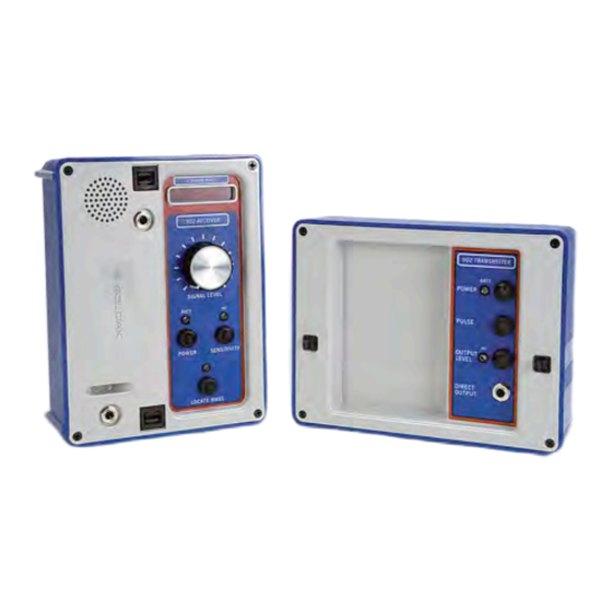
The Goldak Model 902 is a hand-held electronic pipe and cable locator, designed according to the classic “split-box” concept. Like its predecessors in the Model TR series, the Model 902 is used to trace underground conductive networks such as water and gas mains, telephone, cable TV and electric power cables, and any con- tinuously conductive pipe or cable. - Page 4 cable to the line to be traced. Section D of this manual, “Operating Procedures,” explains these transmission meth- ods in greater detail. A detailed explanation of the transmitter features and controls follows here (refer to Fig. 1): a) The POWER Switch. This booted push-button switch controls the power state of the transmitter.
-
Page 5: Receiver
Model 902 Pipe & Cable Locator c) The PULSE Switch. This switch controls whether the signal generated by the transmitter is continuous or pulsed at a frequency of 5 to 10 times per second. Pulsing the signal allows it to be easily identified and also conserves the transmitter's batteries. - Page 6 Procedures,” contains more details about these locating methods and others. Specific features and controls found on the 902 receiver panel are described here (refer to Fig. 2): a) The POWER Switch. This push-button switch activates and deactivates the receiver. The receiver is activated (“on”) when the POWER switch is depressed so that the...
- Page 7 That is, this switch controls the receiver’s overall sensitivi- ty to the signal produced by the 902 transmitter. The LED indicator above this switch monitors what the present sensitivity mode of the receiver is. (NOTE: This switch does NOT control the sensitivity of the receiver while in “locate mass”...
-
Page 8: Direct-Connection Cable (Dcc)
Speaker. A water-resistant, small but powerful mylar speaker delivers a strong audio output corresponding to the signal received by the 902. In tracing mode, the sound will track the LED meter response; however, in mass- locating mode, the speaker delivers a continuous tone, the frequency of which will rise when the receiver is brought near to a metallic mass. -
Page 9: Ground Rod
The Model GC-2 clamp is sold separately. 6. Headphones are also sold separately from the Model 902. Any set of headphones may be used with the Model 902 Locator, provided it has a standard quarter-inch plug. We recommend a comfortable “walkman” style of headphones,... -
Page 10: Carrying Bag
7. Carrying Bag. There are two kinds of carrying bag available for the 902 locator, both constructed from rugged nylon canvas. The smaller bag comes with the instrument originally and con- tains only enough room to carry the instrument and its basic set of accessories. - Page 11 2. Receiving Modes. As for the transmitter, there are two general modes of loca- tion for the 902 receiver: line tracing and mass locating. For line tracing, the operator may choose between two discrete levels of receiver sensitivity.
-
Page 12: Operating Procedures
D. Operating Procedures: 1. Energizing a Line to be Traced. The Model 902 is an "active" locator. This means that the 902 receiver is designed to detect lines that have been ener- gized by the signal generated from the 902 transmitter. - Page 13 Model 902 Pipe & Cable Locator by the radiated signal, the metallic line behaves like a large antenna, retransmitting the signal through the ground and air in a pattern that corresponds to its path. The line carries the signal on its path for several hundred...
- Page 14 iv) Place the transmitter on the ground at a known location directly above the line that you want to energize. As depicted in Figure 5, it is important to place the transmit- ter vertically and in the direction of the underground line. Since the transmitter radiates a signal directionally, this orientation over the line will optimize the signal transfer into the line.
-
Page 15: B) Conductive Energizing
Model 902 Pipe & Cable Locator of the line (Figure 6). The signal entering the line will still be nearly optimized, and line tracing near the trans- mitter box will be much truer. b) Conductive Energizing Unlike the inductive method, this energizing method requires the line to be exposed so that a direct connection can be made to it. -
Page 16: Tracing An Energized Line
(Figure 8). In general, the strength of the signal is strongest at the cen- ter of this cylinder and gradually decreases away from the center. The 902 receiver employs a directional antenna, so... -
Page 17: A) Peak Detection Method
“peaks”, is the most intuitive method of tracing, although not the most accurate. Both location and direction of a line can be determined simply by positioning the 902 receiver so that it indicates a maximum relative response. The following steps illustrate how this is accomplished. - Page 18 iv) Now move the receiver back and forth, causing the meter and sound response to increase and decrease and "peak" over the line. Continue peaking over the line as you walk in the direction of the line; the line will be directly below where the signal response is maximum as you walk.
- Page 19 Model 902 Pipe & Cable Locator sensitivity of the receiver, turn the SIGNAL LEVEL control in the clockwise direction, keeping the response between 1/4 to around 3/4 scale. When the signal from the line has faded so that it is no longer detectible, push the SENSITIVITY button so that the HI light glows.
-
Page 20: B) Null Detection Method
b) Null Detection Method Also called “centering,” tracing a line by finding points where the signal vanishes (“nulls”) is an alternate method to peaking. Because the receiver relies on a directional antenna, positioning it so that the front panel perfectly faces the line will cause it to detect no signal. - Page 21 Model 902 Pipe & Cable Locator i) Turn on the receiver and prepare for tracing as described in steps (i) and (ii) of section (a), Peak Detection Method. ii) Hold the receiver flat with respect to the surface above the line (Figure 11a). Set the SIGNAL LEVEL control between half and full scale.
-
Page 22: C) Determining Depth Of A Line
iv) As with the peak method, the signal on the line will gradually diminish as you continue to trace. Notice that as you trace further away from the transmitter, the null becomes wider and less sharp. To sharpen the null, continue to advance the SIGNAL LEVEL control. - Page 23 Model 902 Pipe & Cable Locator ii) Using the null method, pinpoint the spot on the surface directly above the line and mark it. iii) Turn the receiver to the 45° position. Use the level on the face of the receiver marked “45° LEVEL GUAGE”...
- Page 24 v) When you have obtained a sharp 45° null, mark the ground there. Note that for accurate results, you should mark the ground directly below the top edge of the bottom of the receiver, in order to account for the physical dimensions of the receiver box.
-
Page 25: Finding Lines Of Completely Unknown Location
Each person should now walk parallel to each other, making sure that the 902 boxes remain in line with each other and at a constant distance from each other. If the... - Page 26 two cross over a line that is at a right angle to the direc- tion they are walking, the transmitter will energize the line while the receiver detects the newly energized line. e) At this time, the person carrying the transmitter should move the transmitter back and forth across the line, caus- ing a maximum response at the receiver.
-
Page 27: Locating Hidden Valve Caps
Model 902 Pipe & Cable Locator 4. Locating Hidden Valve Caps and Manholes. The 902 receiver incorporates a feature that makes locating masses of metal buried below the surface simple and con- venient. Activating the LOCATE MASS button reconfigures the receiver antenna, making it sensitive to nearby metallic masses, such as manholes and valve caps. - Page 28 c) When the receiver passes over a mass, the frequency will increase. The rise in frequency depends on the proximity of the buried mass. A sharp increase indicates a shallow mass, probably no more than 6 inches deep. A slight increase indicates a depth probably greater than a foot.
-
Page 29: Miscellaneous Notes And Suggestions
Model 902 Pipe & Cable Locator E. Miscellaneous Notes and Suggestions: 1. Energizing Lines. a) When energizing a line inductively, avoid setting the transmitter directly on the line or within a foot of large masses of metal. The transmitter will continue to func- tion under these conditions, but the energizing efficien- cy might be reduced considerably. -
Page 30: Instrument Maintenance
F. Instrument Maintenance: 1. Battery Replacement. Both parts of the Model 902 Locator are powered by four alkaline “C” size batteries each (Eveready # E-93). When the transmitter and receiver are on, the power supply of each is constantly monitored by its own BATT light. When... -
Page 31: Mechanical Care
2. Mechanical Care. a) Although the Model 902 Locator has been designed to be rugged and can withstand a reasonable amount of shock, it should be handled with care. Heavy shock... - Page 32 then the transmitter is probably working properly, but the batteries are low. You may verify activation of the receiver by pressing either of the SENSITIVITY or LOCATE MASS buttons. If the status light accompany- ing the button glows, then the receiver is probably operating on low batteries.
-
Page 33: Servicing
Model 902 Pipe & Cable Locator G. Servicing: For more technical information about the Model 902, or if servicing and repairs are necessary, contact the factory at the following address: Goldak, Inc. 15835 Monte Street, Unit 104 Sylmar, CA 91342...
Need help?
Do you have a question about the 902 and is the answer not in the manual?
Questions and answers