Table of Contents
Advertisement
Quick Links
3-3/8" PROGRAMMABLE SPEEDOMETER
INSTALLATION INSTRUCTIONS
BACKLIGHT: LED
OPERATING VOLTAGE: 9-32 VDC
INPUT: MAGNETIC SENSOR, HALL EFFECT SENSOR OR PULSE GENERATOR
TRANSIENT PROTECTION: +100V, -400V
REVERSE VOLTAGE: PROTECTED
CALIBRATION: 450 PULSES PER MILE (PPM) TO 200,000 PPM (693,000 PPM max for 30 MPH gauge)
1
Disconnect batteries. Do not reconnect battery power until wiring is fully
completed to avoid risk of shock or fire.
2
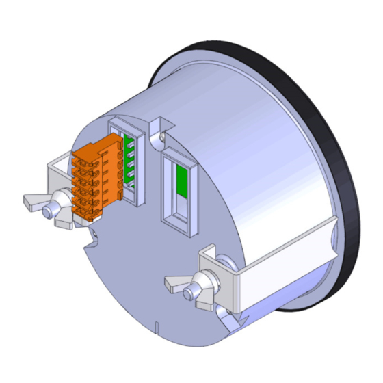
Connect wiring harness to the vehicle as listed below:
Pin 1 – Not used
Pin 2 – Red/Yellow: 5V output, used if a speed sensor (e.g., Hall Effect sensor) requires a 5V source.
Pin 3 – Black: Ground; connect to a clean ground, such as a factory ground bolt.
Pin 4 – Red: Gauge Power; connect to a circuit that switches on with the key switch. If the circuit does
not have a fuse or the existing fuse is higher than 3 amps, use a 3 amp inline fuse.
Pin 5 – Green: Speedometer input (see input list above); connect to the output of the speed sensor.
CARE SHOULD BE TAKEN WHEN ROUTING THIS WIRE FROM THE ENGINE COMPARTMENT TO THE
INTERIOR. SECURE THE WIRE SUCH THAT IT DOES NOT INTERFERE WITH MOVING PARTS AND USE A
GROMMET WHEN PASSING THROUGH THE FIREWALL OR ANY SHARP EDGES.
Pin 6 – Orange: Dimmer; connect to the factory dimmer circuit either by tapping into the in-cab fuse
block or by connecting directly to the wire running from the dimmer on the headlight switch.
ISSPRO, INC.
2515 N.E. Riverside Way
•
503-528-3400
800-888-8065
•
www.isspro.com
© 2010 ISSPRO, Inc. All Rights Reserved.
GENERAL INFORMATION
INSTALLATION
Post Office Box 11177
•
Fax: 503-528-3495
•
Portland, Oregon 97211-1899
•
I C O N K E Y
CAUTION
Tools may be required
Shown in picture
Form No. IS211 (Rev. A 08.12.16)
Advertisement
Table of Contents

Related Manuals for Isspro EV2

Summary of Contents for Isspro EV2
- Page 1 Form No. IS211 (Rev. A 08.12.16) ISSPRO, INC. 2515 N.E. Riverside Way Post Office Box 11177 Portland, Oregon 97211-1899 • • • 503-528-3400 800-888-8065 Fax: 503-528-3495 • • www.isspro.com © 2010 ISSPRO, Inc. All Rights Reserved.
- Page 2 • The speed light will continuously flash twice to indicate Program 2 and the display indicates bACL. Form No. IS211 (Rev. A 02.23.15 ISSPRO, INC. 2515 N.E. Riverside Way Post Office Box 11177 Portland, Oregon 97211-1899 • • • 503-528-3400 800-888-8065 Fax: 503-528-3495 • • www.isspro.com © 2010 ISSPRO, Inc. All Rights Reserved.
- Page 3 To discard the new value without saving, turn power off. DISPLAY FIRMWARE VERSION Form No. IS211 (Rev. A 02.23.15 ISSPRO, INC. 2515 N.E. Riverside Way Post Office Box 11177 Portland, Oregon 97211-1899 • • • 503-528-3400 800-888-8065 Fax: 503-528-3495 • • www.isspro.com © 2010 ISSPRO, Inc. All Rights Reserved.
- Page 4 Figure 1 Programming Overview Form No. IS211 (Rev. A 02.23.15 ISSPRO, INC. 2515 N.E. Riverside Way Post Office Box 11177 Portland, Oregon 97211-1899 • • • 503-528-3400 800-888-8065 Fax: 503-528-3495 • • www.isspro.com © 2010 ISSPRO, Inc. All Rights Reserved.
Need help?
Do you have a question about the EV2 and is the answer not in the manual?
Questions and answers