Table of Contents
Advertisement
Quick Links
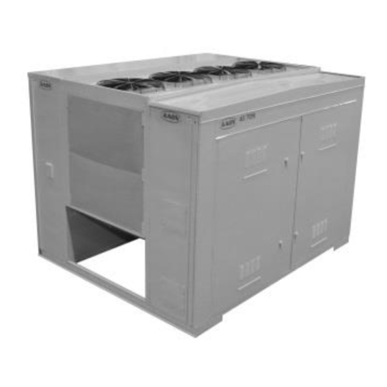
Chillers and Outdoor Mechanical Rooms
Installation, Operation,
WARNING
FIRE OR EXPLOSION HAZARD
Failure to follow safety warnings
exactly could result in serious injury,
death or property damage.
Be sure to read and understand the
installation, operation and service
instructions in this manual.
Improper
installation,
alteration, service or maintenance can
cause serious injury, death or property
damage.
A copy of this IOM should be kept with
the unit.
& Maintenance
adjustment,
LN Series
WARNING
Do not store gasoline or other
flammable vapors and liquids in the
vicinity of this or any other appliance.
WHAT TO DO IF YOU SMELL GAS
Do not try to light any appliance.
Do not touch any electrical switch;
do not use any phone in your
building.
Leave the building immediately.
Immediately call you gas supplier
from a phone remote from the
building. Follow the gas supplier's
instructions.
If you cannot reach your gas
supplier call the fire department.
Startup
and
service
performed by a Factory Trained
Service Technician.
must
be
Advertisement
Table of Contents

Related Manuals for AAON LN Series


Summary of Contents for AAON LN Series
- Page 1 LN Series Chillers and Outdoor Mechanical Rooms Installation, Operation, & Maintenance WARNING WARNING FIRE OR EXPLOSION HAZARD Do not store gasoline or other flammable vapors and liquids in the Failure to follow safety warnings vicinity of this or any other appliance.
-
Page 2: Table Of Contents
E-Coated Coil Cleaning ......................33 Microchannel Coil Cleaning ..................... 36 Service ............................38 Replacement Parts ........................38 AAON Technical Support ......................38 Automatic Air Vent Valves ....................... 39 Pumps - Installation and Operating Instructions ............... 41 Pump Piping - General ......................42 Pump Operation ......................... - Page 3 Index of Tables and Figures Tables: Table 1 - Service Clearances......................18 Table 2 - Mounting Dimensions ....................19 Table 3 - Nameplate Voltage Markings ..................22 Table 4- Tandem Circuited Variable Speed Compressor VFD Frequency Range ....... 24 Table 5 - Return/Exhaust Fan Pin Location .................. 27 Table 6 - Return/Exhaust Fan Pin Location ..................
- Page 4 ® AAON LN Series Features and Options Introduction Energy Efficiency Installation and Maintenance High Efficiency Air-Cooled Run Test Report and Installation Manuals Microchannel Condenser Included in Controls Compartment Staged or Tandem VFD Controlled Color Coded Wiring Diagrams Variable Speed R-410A Scroll ...
- Page 5 Safety Attention should be paid to the following statements: NOTE - Notes are intended to clarify the unit installation, operation and maintenance. CAUTION - Caution statements are given to prevent actions that may result in equipment damage, property damage, or personal injury. WARNING - Warning statements are given to prevent actions that could result in equipment damage, property damage, personal injury or death.
- Page 6 WARNING WARNING FIRE, EXPLOSION OR CARBON GROUNDING REQUIRED MONOXIDE POISONING HAZARD All field installed wiring must be Failure to replace proper controls completed by qualified personnel. could result in fire, explosion or Field installed wiring must comply with carbon monoxide poisoning. Failure to NEC/CEC, local and state electrical follow safety warnings exactly could code requirements.
- Page 7 WARNING CAUTION UNIT HANDLING PVC (Polyvinyl Chloride) and CPVC (Chlorinated Polyvinyl Chloride) are To prevent injury or death lifting vulnerable attack certain equipment capacity shall exceed unit chemicals. Polyolester (POE) oils weight by an adequate safety factor. used with R-410A other Always test-lift unit not more than 24 refrigerants, even in trace amounts, in...
- Page 8 WARNING WARNING Some chemical coil cleaning COMPRESSOR CYCLING compounds are caustic or toxic. Use these substances only in accordance 3 MINUTE MINIMUM OFF TIME with manufacturer’s usage prevent motor overheating instructions. Failure follow compressors must cycle off for a instructions may result in equipment minimum of 3 minutes.
- Page 9 LN Series Feature String Nomenclature Model Options Unit Feature Options LN A F A C 0 E 0 0 0 0 – – – – – – – 0 0 0 0 – 0 0 0 0 – 0 0 0 0 – 0 0 – 0 0 0 – 0 – 0 E 0 0 –...
- Page 10 LN Series Feature String Nomenclature Model Options Unit Feature Options 0 0 0 LN A – 140 – C – A – 3 – F A C 0 E – 0 0 0 0 : A 0 – 0 – 0 0 0 0 – 0 0 0 0 – 0 0 – 0 0 0 – 0 – 0 E 0 0 –...
- Page 11 LN Series Feature String Nomenclature Model Options Unit Feature Options 0 0 0 0 0 0 0 0 0 0 0 0 E 0 LN A – 140 – C – A – 3 – F A C 0 E – 0 0 0 0 : A 0 – 0 0 0 –...
- Page 12 LN Series Feature String Nomenclature Model Options Unit Feature Options LN A – 140 – C – A – 3 – F A C 0 E – 0 0 0 0 : A 0 – 0 0 0 0 – 0 0 0 0 – 0 0 0 0 – 0 0 – 0 0 0 – 0 – 0 E 0 –...
- Page 13 28: BLANK X = Special Pricing Authorization + Premium AAON 0 = Standard Gray Paint Exterior 1 = SPA + Premium AAON Gray Paint Exterior + 29: BLANK Shrink Wrap 0 = Standard 4 = Special Pricing Authorization + Special Exterior...
-
Page 14: Codes And Ordinances
General Information CAUTION AAON LN Series chillers are complete self- The Clean Air Act of 1990 bans the contained liquid chilling units. They are intentional venting of refrigerant as of assembled, wired, charged and run-tested. July 1, 1992. Approved methods of... -
Page 15: Storage
handling damaged goods, repairs, and freight Never turn off the main power supply to the claims: (918) 382-6450. unit, except for complete shutdown. When power is cut off from the unit, any Storage compressors using crankcase heaters cannot If installation will not occur immediately prevent refrigerant migration. -
Page 16: Wiring Diagrams
Never cut off the main power supply to the Chiller Primary Pumping unit, except for complete shutdown. Always Primary pumping uses a single pump to move control the system from the building water (or glycol) through the chiller barrel management system, or control panel, never and back to the building. -
Page 17: Automatic Air Vent
the other two needle valves. One gauge is Automatic Air Vent There is an automatic air vent installed at the used so that the calibration of the pressure high point of the system inside the pumping gauge is irrelevant in the calculation of the package compartment. -
Page 18: Chiller Placement
Installation Unit specific curb drawing is included with Chiller Placement job submittal. See SMACNA Architectural The AAON LN Series is designed for Sheet Metal Manual for curb installation outdoor applications and mounting at ground details. level or on a rooftop. It must be placed on a level and solid foundation that has been prepared to support its weight. -
Page 19: Lifting And Handling
Lifting and Handling If cables or chains are used to hoist the unit they must be the same length and care should be taken to prevent damage to the cabinet. See Figure 5 and Figure 6 for additional information. Before lifting unit, be sure that all shipping material has been removed from unit. -
Page 20: Figure 5 - Lifting Detail Of A 45-60 Ton Unit
Figure 5 - Lifting Detail of a 45-60 ton Unit Figure 6 - Lifting Detail of a 75-140 ton Unit Lifting slot locations are unit specific. Unit must be rigged at all marked lifting points. -
Page 21: Water Connection
CAUTION End Flashing Installation PVC (Polyvinyl Chloride) and CPVC On all LN Series units the cabinet width will (Chlorinated Polyvinyl Chloride) are overhang the shipping trailer on each side. vulnerable attack certain chemicals. -
Page 22: Low Ambient Operation
Size supply conductors based on the unit CAUTION MCA rating. Supply conductors must be rated a minimum of 167°F (75°C). In order to prevent water leakage into the roof curb, the factory provided Route power and control wiring, separately, sheet metal flashings MUST BE through the utility entry. -
Page 23: Figure 8 - Front View Of Utility Entry And Power Switch From Control Compartment
Wire control signals to the unit’s low voltage terminal block located in the controls compartment. All wiring beyond this point has been completed by the manufacturer and cannot be modified without effecting the unit’s agency/safety certification. CAUTION Scroll compressors are directional and will be damaged by operation in the wrong direction. -
Page 24: Variable Speed Compressors
Voltage imbalance is defined as 100 times the Table 4- Tandem Circuited Variable Speed maximum deviation from the average voltage Compressor VFD Frequency Range divided by the average voltage. Compressor VFD Model (LN-) Range (Hz) Example: 208V, 230V, 460V and 575V Units (218V+237V+235V)/3 230V, then... - Page 25 Use the general check list at the top of the Startup startup form to make a last check that all the (See back of the manual for startup form) components are in place, water flow is present, and the power supply is energized. WARNING Using the controller keypad, individually set the outputs in “Manual On”...
-
Page 26: Axial Flow Condenser Fans
Location A is with the bushing mount on air Axial Flow Condenser Fans inlet side of the fan. Multi-Wing Z Series Aluminum Fan Blade Location B is with the bushing mount on air Pitch Angle Setting Instructions discharge side of the fan. 1. -
Page 27: Table 5 - Return/Exhaust Fan Pin Location
5. Determine whether the pin is in the HUB or RET Figure 12 - Fan HUB and RET Castings 6. Determine the current blade pitch and the pin location for the new blades Table 5 - Return/Exhaust Fan Pin Location Blade Pitch Angle Bushing Type... -
Page 28: Table 7 - Fan Assembly Bushing Torque Specifications
4. Replace blades to their original location. Angle Setting Instructions 5. Replace all nuts, bolts, and washers on the Contact the AAON parts department to fan hub. acquire the new pitch pins for the fan blades. 6. Replace retaining plates and center boss to Note original position of retaining plates, original location. -
Page 29: General
WARNING Maintenance Service gauges MUST BE connected General before operating the isolation valves Qualified technicians must perform routine for the replaceable core filter. service checks and maintenance. This includes reading recording condensing and suction pressures and Suction Filter Removal Instructions checking for normal sub-cooling and... -
Page 30: Adjusting Refrigerant Charge
Adjusting Refrigerant Charge All AAON chillers are shipped with a full After adding or removing charge the system factory charge. Periodically adjusting the must be allowed to stabilize, typically 10-15 charge of a system may be required. -
Page 31: Table 8 - Acceptable Refrigeration Circuit Values
Checking Evaporator Superheat Table 8 - Acceptable Refrigeration Circuit Measure the temperature of the suction line Values close to the compressor. Air-Cooled Chiller with Scroll Compressors Read gauge pressure at the suction line close Sub-Cooling 12-18°F to the compressor. Superheat 10-15°F One compressor running in tandem Convert the pressure obtained to a saturated... -
Page 32: Table 9 - R-410A Refrigerant Temperature-Pressure Chart
Table 9 - R-410A Refrigerant Temperature-Pressure Chart psig psig psig psig psig 78.3 142.2 234.9 364.1 540.1 80.0 144.8 238.6 369.1 547.0 81.8 147.4 242.3 374.2 553.9 83.6 150.1 246.0 379.4 560.9 85.4 152.8 249.8 384.6 567.9 87.2 155.5 253.7 389.9 575.1 89.1... -
Page 33: Lubrication
Rotate the fan shaft by hand and add only coils is required to maintain coating warranty enough grease to purge the seals. DO NOT coverage. E-Coated Coil Maintenance Record document is available on the AAON OVERLUBRICATE. website. Air-Cooled Condenser The air-cooled condenser section rejects heat... - Page 34 Quarterly cleaning is required to maintain CAUTION warranty coverage and is essential to maintain the life of an E-coated coil. Coil Harsh chemicals, household bleach, cleaning shall be part of the unit's regularly or acid cleaners should not be used to scheduled maintenance procedures.
- Page 35 loose debris will not be blown into the coil and slowly move vertically coil. downward to the bottom. Then, 3. Remove panels or tops as required staying in the same vertical area, gaining access to the coil(s) to be slowly move back up to the top where cleaned.
-
Page 36: Microchannel Coil Cleaning
AAON will warrant as correct and are thoroughly rinsed. for cleaning microchannel coils. 6. Reinstall all panels and tops that were There are three procedures that are outlined removed. - Page 37 Spray from the fan side #1 Simple Green Simple Green is available from AAON Parts of the coil. Supply (Part# T10701) 2. Spray and rinse the coil from the face. biodegradable with a neutral 6.5 pH.
-
Page 38: Service
AAON testing has determined that unless a chemical has a neutral pH (6-8) it should not be used. Beware of any product that claims to be a foaming cleaner. The foam that is generated is caused by a chemical reaction to the... -
Page 39: Automatic Air Vent Valves
Appendix - Water Piping Component Information Automatic Air Vent Valves Automatic Vent Valves provide automatic air venting for hot or cold water distribution systems. These vents purge air that may be in the water system. The vent valve utilizes a float to actuate the valve plug which is located at the top of the valve. - Page 40 of at least 1⁄2" diameter between the “Float Vent” valves and installation. Installation When the air vent valve is installed as shown, the air will not be vented while the fluid is circulating in the system, but it can vent when the system is shut off.
-
Page 41: Pumps - Installation And Operating Instructions
Dimensions – Weights: Pumps - Installation and Operating Where under normal operating conditions the Instructions limit of 68°C/155°F (Restricted Zone) for Introduction normal touch, or 80°C/176°F (Unrestricted This document contains specific information Zone) for unintentional touch, may be regarding the safe installation, operating, and experienced, steps should be taken to maintenance of Vertical In-Line pumps and minimize contact or warn operators/users that... -
Page 42: Pump Piping - General
rotating element free and bearings fully Vertical Inline Pump Lifting Strap functional. Positioning: For long term storage, the pump must be placed in a vertical position in a dry environment. Internal rusting prevented by removing the plugs at the top and bottom of the casing and drain or air blow out all water to prevent rust buildup or the possibility of freezing. -
Page 43: Pump Operation
valve may be ‘cracked’ or open slightly at Alignment Alignment is unnecessary on close-coupled start up to help eliminate trapped air. pumps as there is no shaft coupling. When stopping the pump: Close the Split-coupled units are accurately aligned at discharge valve and de-energize the motor. -
Page 44: General Care
Check rotation arrow prior to operating the Large Series split-coupled units are installed unit. The rotation of all Vertical In-Line units with a shaft bushing located beneath the is “clockwise” when viewed from the drive impeller that is lubricated from the pump end. - Page 45 Mechanical seals may ‘weep’ slightly at Note start-up. Allow the pump to continue Particular care must be taken to check the operating several hours following before the pump is put into mechanical seal to ‘seat’ properly prior to operation: calling for service personnel. 1.
-
Page 46: Dual Pump Specific Information
Vibration Levels Vertical In-Line pumps are designed to meet vibration levels set by Hydraulic Institute Standard HI Pump Vibration 9.6.4. Standard levels are as detailed below: Dual Pump Specific Information Procedure for Starting the Pump after Servicing 1. Ensure serviced pump is fully re- Dual Pump Flapper Valve Operating assembled including all seal flush lines Instructions... - Page 47 5. Tighten set screw (11) to lock the locking Discharge Valve This valve performs the dual function of handle (3) in position. automatically sealing the discharge of the inactive pump when one pump is running and This handle should not be rotated past the can manually be closed and locked to isolate vertical position.
- Page 48 2. Rotate the suction side locking handle (3) so that the handle points towards the WARNING pump to be serviced and secure in the horizontal position, using set screw (11). Care should taken when This releases the suction locking arm (4). performing procedures 3 and 4.
-
Page 51: Suction Guides
Suction Guides Introduction Suction Guides are designed for bolting directly onto the suction flange of horizontal or vertical shaft centrifugal pumps. Operating Limits The suction guide is designed to be a four- Inspection function fitting. Each Suction Guide is a 90º Suction Guides are thoroughly tested and elbow, a Pipe Strainer and a Flow Stabilizer. -
Page 52: Flo-Trex Combination Valve
place. This will be detrimental to the Insert two bolts of specified size (Table A1) operation of the pump. to secure the halves of the flange adapter to the valve body (as shown). Inspect the cover O-ring and replace if necessary. - Page 53 4. Position the adjoining flange or the pipe to the Armgrip flange adapter and install the remaining bolts. The two locking Recommended Bolt Tightening Procedure bolts should be tightened first in order to position the flange correctly. Field Conversion (Straight to Angle Pattern Valve: Note: Care should be taken to ensure that 1.
- Page 54 Flow Measurement with the valve in the Wide Open position Where approximate indication of flow is acceptable the Flo-Trex valve can be used. Step 1. Measure and record the differential Step 2. With valve in fully open position, pressure across the valve. locate the pressure differential on left hand side of the Flo-Trex Performance Curve with Valve in Full Open Position chart and extend...
- Page 55 with the Valve Characteristic Curve and from Flow Measurement with the valve in the throttled position this point project line horizontally across to the left of the chart and record the percentage Step 1. The valve stem with its grooved rings of maximum flow rate.
- Page 56 Step 2. Turn the valve stem counterclockwise Example Continued: From the Flo-Trex performance curve, a 4in. until the valve is fully open and will not turn valve with 5.4 ft of pressure drop represents any further. Torque to a maximum of a flow of 400 USgpm 45 ft-lbs.
- Page 57 Pressure-Temperature Limits Flo-Trex Cross Section...
- Page 58 LN Series Startup Form Job Name:_____________________________________________ Date:____________ Address:____________________________________________________________________ ____________________________________________________________________________ Model Number:_______________________________________________________________ Serial Number:___________________________________________ Tag:___________ Startup Contractor:____________________________________________________________ Address:____________________________________________________________________ _____________________________________________________ Phone:____________ Pre Startup Checklist Installing contractor should verify the following items. 1. Is there any visible shipping damage? 2. Is the unit level? 3.
- Page 59 Water/Glycol System 1. Has the entire system been flushed and pressure checked? 2. Have isolation valves to the chiller been installed? 3. Has the entire system been filled with fluid? 4. Has air been bled from the heat exchangers and piping? 5.
- Page 60 Refrigeration System 1 - Cooling Mode Saturated Line Pressure Sub-cooling Superheat Temperature Temperature Discharge Suction Liquid Refrigeration System 2 - Cooling Mode Saturated Line Pressure Sub-cooling Superheat Temperature Temperature Discharge Suction Liquid Condenser Fans Alignment Check Rotation Nameplate Amps________ Number Pumping Package Flow (gpm) Chiller Building Pump #1...
- Page 61 This log must be kept with the unit. It is the responsibility of the owner and/or maintenance/service contractor to document any service, repair or adjustments. AAON Service and Warranty Departments are available to advise and provide phone help for proper operation and replacement parts.
- Page 63 Literature Change History February 2014 Initial version. July 2014 Corrected tonnages for the figures of the lifting details. January 2015 Updated cover picture and Feature 17-H minimum operation temperature. July 2015 Updated Microchannel Coil Cleaning section. Updated Flo-Trex images. Added Features and Options Information.
- Page 64 Parts: For replacement parts, please contact your local AAON Representative. It is the intent of AAON to provide accurate and current product information. However, in the interest of product improvement, AAON reserves the right to change pricing, specifications, and/or design of its product without notice, obligation, or liability.
Need help?
Do you have a question about the LN Series and is the answer not in the manual?
Questions and answers