
Summary of Contents for Lenze LDEC Series
- Page 1 LDEDS−CCU210B .Jf$ System Manual LDEC LDECBBF1xxxxxxHx Carriage control systems for monorail overhead conveyors...
- Page 2 0Fig. 0Tab. 0...
-
Page 3: Table Of Contents
............General safety and application notes for Lenze control systems . - Page 4 Contents Digital output signals ..........8.4.1 Description .
-
Page 5: About This Documentation
This System Manual is directed to all persons dimensioning, installing, commissioning and adjusting monorail overhead conveyors with carriage control systems. Tip! Information and auxiliary devices related to the Lenze products can be found in the download area at http://www.Lenze.com Document history... -
Page 6: Conventions Used
About this documentation Conventions used Conventions used Type of information Identification Examples/notes Spelling of numbers Decimal separator language−dependen In each case, the signs typical for the target language are used as decimal separators. For example: 1234.56 or 1234,56 Text Program name »... -
Page 7: Notes Used
About this documentation Notes used Notes used The following pictographs and signal words are used in this documentation to indicate dangers and important information: Safety instructions Structure of safety instructions: Danger! (characterises the type and severity of danger) Note (describes the danger and gives information about how to prevent dangerous situations) Pictograph and signal word Meaning... -
Page 8: Safety Instructions
(in accordance with Low−Voltage Directive 2006/95/EC) General Lenze controls can have live, even moving or rotating parts during operation − according to their enclosure. Surfaces can be hot. The unauthorised removal of the required cover, improper use, incorrect installation or operation will risk serious personal injury and damage to property. - Page 9 General safety and application notes for Lenze control systems Application as directed The Lenze control system is designed for operation on a travelling drive (short−time brake applications permissible only). Without protection of persons (optional) the control system is not suitable for hoist applications! Lenze control systems are components intended for installation in electrical systems or machines.
- Page 10 You may have to fit additional monitoring and protection devices to systems with built−in Lenze control systems in accordance with relevant safety regulations (e.g. law on technical equipment, regulations for the prevention of accidents). You may adjust the Lenze control systems to your application.
-
Page 11: Residual Hazards
Safety instructions Residual hazards Residual hazards Protection of persons The X1 power connector contacts (supply via flat connector field) can conduct ƒ hazardous voltages if the control system is connected to the mains. Therefore disconnect the control system before carrying out any work on it. The X2 power connector contacts also conduct hazardous voltages. -
Page 12: Device Description
Device description Device features Device description Device features Vehicle control system Description LDECBBF1xxxxxxHW Travelling drive for monorail overhead conveyors (MOC), frequency−controlled LDECBBF1xxxxxxHC Energy supply 3/PE/PEN AC 360 V − 0 % ... 528 V + 0 % 0.75/ 1.5/ 2.2 kW Connection of an external data memory to the control system Halve wave selection Halve wave feedback signal... -
Page 13: Overview
Device description Overview Overview Power 0.75 kW CCU210_002H Operational control and connections Pos. Function Description ^ 81 Important fault messages Short description of the most important fault messages ^ 78 Status display of device (LED) Readiness for operation, error Infrared receiver ... ^ 65 ... - Page 14 Device description Overview Power 1.5 kW CCU210_002A Operational control and connections Pos. Function Description ^ 81 Important fault messages Short description of the most important fault messages ^ 78 Status display of device (LED) Readiness for operation, error Infrared receiver ... ^ 65 ...
- Page 15 Device description Overview Power 2.2 kW CCU210_002A Operational control and connections Pos. Function Description ^ 81 Important fault messages Short description of the most important fault messages ^ 78 Status display of device (LED) Readiness for operation, error Infrared receiver ... ^ 65 ...
-
Page 16: Type Code
Type code Type code This documentation is valid for LDEC carriage control systems as of nameplate data: Nameplate Manufacturer code H ans- Lenze- St r asse 1 D - 31855 Aer zen Product Product family Order no. Material Type... - Page 17 Device description Type code Legend for LDECBBF1xxxxxxHW type code 0 Manufacturer code Lenze 1 Product family Local control unit Inductive control unit Conductive control unit General accessories 2 Equipment line Baseline Stateline Highline 3 Generation 1st generation 2nd generation 4 Design...
- Page 18 Device description Type code 9 Power of third axis / variants, customer version = 0.55kW = 0.75kW = 1.1kW = 2.2kW = 4.0kW = 7.5kW = 10.0kW Labelling (variants_customer version) Other characters Not relevant For the entry of numbers LDEDS−CCU210B EN 4.0...
-
Page 19: Technical Data
Technical data General data and operating conditions Technical data General data and operating conditions General data Conformity and approval Conformity 2006/95/EC Low−Voltage Directive 93/68/EEC EMC Directive (basis 89/336/EEC) Protection of persons and equipment Degree of protection EN 60529 IP54 Cover all unused connectors with protective caps or dummy plugs. - Page 20 Technical data General data and operating conditions Operating conditions Ambient conditions Climatic Storage IEC/EN 60721−3−1 1K3 (−25 ... +70 °C) < 6 months 1K3 (−25 ... +40 °C) > 6 months > 2 years: form DC−bus capacitors Transport IEC/EN 60721−3−2 2K3 (−25 ...
-
Page 21: Rated Data
Output current Duration For 60 s Switching frequency Optionally f [kHz] 2, 4, 8 Lenze setting f [kHz] Motor output frequency f [Hz] 0 ... 120 variable Power loss at rated load Power loss in idle state (only half wave power, 24V−sensors are not connected) - Page 22 Technical data Rated data Half wave system Control bar Z system Number Signal level Full wave Positive half wave Negative half wave Reference voltage or switched voltage L1 possible with different hardware configuration Rated voltage 400 ... 480 V AC, 50−60 Hz Switching threshold 50 Hz: 270 V AC (243 ...
-
Page 23: Mechanical Installation
Mechanical installation Important notes Mechanical installation Important notes Never install or commission damaged products. Please complain about damage ƒ immediately to the forwarder. Only mount the control system if the data on the nameplate of the control system ƒ correspond to the voltage mains. Ensure that the mounting location fulfils the following conditions: ƒ... -
Page 24: Dimensions
Mechanical installation Dimensions Dimensions Power 0.75 kW CCU210_002H LDEDS−CCU210B EN 4.0... - Page 25 Mechanical installation Dimensions Power 1.5 kW CCU210_002B LDEDS−CCU210B EN 4.0...
- Page 26 Mechanical installation Dimensions Power 2.2 kW CCU210_002_2_2kW LDEDS−CCU210B EN 4.0...
-
Page 27: Electrical Installation
Electrical installation Important notes Electrical installation Important notes Danger! The contacts for the X1 and X2 power connectors can carry dangerous ƒ voltages when the control system is connected to the mains. Therefore deenergise the control system before working on it. After the connection of a PTC thermistor or a thermal switch (NC contact), ƒ... - Page 28 Electrical installation Important notes EMC−compliant wiring Note! In order to ensure the trouble−free operation of Lenze control systems on monorail overhead conveyors, an EMC−compliant installation is requried. This includes the following: Conduct the motor cable as described in the technical data.
-
Page 29: Basic Circuit Diagram
Electrical installation Basic circuit diagram Basic circuit diagram Power 0.75 kW CCU210_105 Control cabinet LDEDS−CCU210B EN 4.0... - Page 30 Electrical installation Basic circuit diagram Power 1.5 kW and 2.2 kW CCU210_105 Control cabinet LDEDS−CCU210B EN 4.0...
-
Page 31: Mains Connection
Electrical installation Mains connection Mains connection CCU210_002C X1 − Mains connection Connection Description Data Connector: FASTON 6.3 x 0.8 mm flat connector, 10−pole Phase L1 3/PE/PEN AC 360 V − 0 % ... 528 V + 0 % 45 Hz − 0 % ... 65 Hz + 0 % Phase L2 Phase L3 PE conductor... -
Page 32: Motor Connection
Electrical installation Motor connection Motor connection CCU210_002D X2 − Motor connection Connection Description Data Connector: Socket, Harting HAN−10B Phase U Phase V Phase W + brake Brake supply voltage +PTC Motor temperature monitoring PTC thermistor (PTC) or thermal contact (NC contact) n.c. -
Page 33: Control Terminals
Electrical installation Control terminals Control terminals Device in a power range of 1.5 kW and 2.2 kW Devices in a power range of 0.75 kW CCU210_002E CCU_210_002G Common control terminals X50 − external data memory Signal Description Data EXMID1 Connector: socket, 8−pole, M12 Connection of external data Max. - Page 34 Electrical installation Control terminals X41 − digital input DIN2 / digital output DOUT1 Signal Description Data Connector: socket, 4−pole, M12 +24V DC Supply HIGH +16 ..+26.5 V DC DOUT1 Digital output 1 0 ... +4 V Reference potential 4 mA Current per input for 24 V DC DIN2 Digital input 2...
- Page 35 Electrical installation Control terminals X45 − digital inputs DIN5/DOUT2 − DIN6 Signal Description Data Connector: socket, 4−pole, M12 +24V DC Supply HIGH +16 ..+26.5 V DC DIN5 Digital input 5 0 ... +4 V DOUT2 Digital output 2 4 mA Current per input for 24 V DC Reference potential max.
-
Page 36: Connection Of System Bus (Can)
The system requirements and the steps required for installing the program are described in the Global Drive Control or Global Drive Control easy user manuals. the device description file (*.pdb) provided by Lenze. The PC uses this file to identify ƒ the control system. - Page 37 Electrical installation Connection of system bus (CAN) Connection to the PC After installing the "Global Drive Control" software program and the device description file, you can connect the device to your PC. 1. Remove the black cover on the control end of the device. Device in a power range of 1.5 kW and 2.2 kW Devices in a power range of 0.75 kW CCU210_002A...
-
Page 38: Commissioning
Commissioning Before switching on Commissioning Before switching on Before initial switch−on, check ..whether the drive is undamaged. ƒ ... the entire wiring with regard to completeness, short circuit and earth fault. ƒ ... whether the mains and the motor are connected in correct phase relation. ƒ... -
Page 39: Switch−On Sequence
Commissioning Switch−on sequence Switch−on sequence Note! Disconnect the control system from the mains before you attach or remove ƒ the external EXMID1 data memory! If the external EXMID1 data memory is attached or removed during voltage ƒ is applied, the data saved on it can be damaged: –... -
Page 40: Function Library
Function library Important notes Function library Important notes Linking signals correctly To operate the controller or to output status messages, you can freely link internal digital and analog signals to sources and targets. You can avoid faults if you observe the following: Always select the source from the target: ƒ... -
Page 41: Operating Mode
Operating mode The vehicle control system is operated in the "V/f characteristic control" operating mode. Codes for parameter setting Code Possible settings Description ñò < Byte Lenze Selection ^ 41 C0015 Operating mode V/f characteristic control Reserved Reserved ^ 41... -
Page 42: Digital Input Signals
For each control bar you can use the digital signals "positive half wave", "negative half wave" and "full−wave" for function links. Note! The reference phase in the Lenze setting is L3. On customer request, the reference phase L1 can be supplied by adapting the hardware. - Page 43 Function library Digital input signals Description Codes for parameter setting Code Possible settings Description ñò < Byte Lenze Selection ^ 42 C0406 Switch−on delay of digital input signals LOW ð HIGH ... 1 RW {ms} 10000 ... DIN1 ... DIN2 ...
-
Page 44: Connection Logic
Digital input signals Connection logic Code Possible settings Description ñò < Byte Lenze Selection ^ 42 C0408 Level inversion for digital inputs à inputs are LOW−active Add values of the inverted inputs: Possible values e. g. DIN1, DIN3 and DIN5 are No inversion LOW−active à... - Page 45 Function library Digital input signals Connection logic Codes for parameter setting Code Possible settings Description ñò < Byte Lenze Selection ^ 44 C0409 Logic operations of digital input signals Link ORx = OR operation Link ANDx = AND operation 1 RW...
-
Page 46: Assignment Logic
By this, you define the desired control functions and responses to specific events. Codes for parameter setting Code Possible settings Description ñò < Byte Lenze Selection ^ 46 C0410 Linking digital input signals to an internal device function ... 1 RW Not assigned ... - Page 47 Function library Digital input signals Assignment logic Code Possible settings Description ñò < Byte Lenze Selection ^ 46 C0410 (Continuation) Linking digital input signals to an internal device function ... Possible values Not assigned DIN1 Digital input DIN1 DIN2 Digital input DIN2...
- Page 48 Function library Digital input signals Assignment logic Code Possible settings Description ñò < Byte Lenze Selection ^ 46 C0410 (Continuation) Linking digital input signals to an internal device function HWC match code 1 HWC match code 1 HWC match code 2...
-
Page 49: Digital Output Signals
A message bar output (MS1) is provided. You can output the digital signals "positive half wave" and "negative half wave". Note! The reference phase in the Lenze setting is L3. On customer request, the reference phase L1 can be supplied by adapting the hardware. -
Page 50: Assignment Logic
In the assignment logic (C0415) you assign internal status signals to the message bar and the digital outputs. Codes for parameter setting Code Possible settings Description ñò < Byte Lenze Selection ^ 50 C0415 Linking internal status signals to digital output signal ... 1 RW Not assigned ...Digital output DOUT1... - Page 51 Function library Digital output signals Assignment logic Code Possible settings Description ñò < Byte Lenze Selection ^ 50 C0415 (Continuation) Linking internal status signals to digital output signal ... Possible values Motor is running Reserved Status On/Off: OFF active Status On/Off: OFF active or fault...
-
Page 52: Motor Control
(C0012/1 ... C0012/8 and C0013/1 ... C0013/8). The direction of rotation is controlled via C0410/9. A second parameter set can be activated via C0410/13. Codes for parameter setting Code Possible settings Description ñò < Byte Lenze Selection ^ 52 C0010 10000 Conversion factor: speed at 50 Hz drive frequency {mm/min}... - Page 53 Function library Motor control "Motor speed V1−V8" function Code Possible settings Description ñò < Byte Lenze Selection ^ 52 C0013 Deceleration time for ... 1 RW {Hz/s} 255 ... V1 ... V2 ... V3 ... V4 ... V5 ... V6 ...
-
Page 54: Stop Functions
You can set each function so that the stop function only is activated in the case of ƒ one direction of rotation of the drive. Codes for parameter setting Code Possible settings Description ñò < Byte Lenze Selection ^ 54 C0430 Configuration of function ... 1 RW ... Stop 1 ... Stop 2 ... Stop 3 ... -
Page 55: Frequency Limitation" Function (Speed Limit)
ƒ case of one direction of rotation of the drive. Codes for parameter setting Code Possible settings Description ñò < Byte Lenze Selection ^ 55 C0440 Configuration of function ... 1 RW ... Frequency limitation 1 ... Frequency limitation 2 ... -
Page 56: Open Brake" Function
If the "Motor V1−V8" functions are active, the motor brake always is open automatically. Codes for parameter setting Code Possible settings Description ñò < Byte Lenze Selection ^ 56 C0450 "Open brake" function: configuration Brake opens immediately Brake opens if C0410/15 = HIGH... -
Page 57: Monitoring
Function library Monitoring Anti−collision sensor SensoPart Monitoring 8.6.1 Anti−collision sensor SensoPart The SensoPart permanently measures the distance to a reflector on the vehicle ahead. The distance is read out via a serial interface RS485 by the vehicle control system and is evaluated according to the function parameterised. - Page 58 Function library Monitoring Anti−collision sensor SensoPart Mode of operation f [Hz] V [mm/min] C0478 C0476 C0468 C0466 C0468 x [mm] C0462 C0464 C0472 CCU210_101 Braking distance for braking to creeping speed, calculated for the respective speed LDEDS−CCU210B EN 4.0...
- Page 59 Codes for parameter setting Code Possible settings Description ñò < Byte Lenze Selection ^ 57 C0128 Configuration of SensoPart error monitoring Error Warning...
- Page 60 Function library Monitoring Anti−collision sensor SensoPart Code Possible settings Description ñò < Byte Lenze Selection ^ 57 C0461 SensoPart: distance for quick disconnection {mm} 65535 ^ 57 C0462 SensoPart: stop distance in ... 1 RW 2000 {mm} 65535 ... Parameter set 1 2000 ...
-
Page 61: I2T Monitoring
Function library Monitoring t monitoring Code Possible settings Description ñò < Byte Lenze Selection ^ 57 C0478 SensoPart: deceleration ramp Vx ð VLx for frequency limitation distance in ... 1 RW {Hz/s} 255 ... Parameter set 1 ... Parameter set 2... - Page 62 I set for approx. 13 s. Codes for parameter setting Code Possible settings Description ñò < Byte Lenze Selection ^ 61 C0022 Rated motor current in ... 1 RW 20.0 ... Parameter set 1 ... Parameter set 2...
-
Page 63: Non−Equivalence Monitoring
In C0403 you set the error deceleration times. Codes for parameter setting Code Possible settings Description ñò < Byte Lenze Selection ^ 63 C0401 Configuration: response of the non−equivalence monitoring at the digital inputs 1 RW 255 Non−equivalence monitoring 1... -
Page 64: Motor Temperature Monitoring
How to eliminate a parameter error: 1. Set all parameters to the Lenze setting (C0002 = 1). 2. Transfer the valid parameter set for the respective application again. 3. Wait until the PAr display goes out. -
Page 65: Infrared Data Transmission (Irda)
Flash lamps, laser scanners or other light sources can interfere the IrDA ƒ transmission! Codes for parameter setting Code Possible settings Description ñò < Byte Lenze Selection ^ 65 C0126 Configuration of IrDA error monitoring Error Warning LDEDS−CCU210B EN 4.0... -
Page 66: Irda Positioning
Function library IrDA positioning IrDA positioning By means of the IrDA positioning, an electric monorail overhead conveyor vehicle can be positioned to a millimeter value specified via fieldbus within the IrDA transmission range of the IRDS data station. This requires the connection of a CAN bus position measuring sensor and a digital reference sensor to the IRDS data station. - Page 67 Exiting the position and thus the deactivation of the positioning function is ƒ triggered by resetting the fieldbus control bit. Codes for parameter setting Code Possible settings Description ñò < Byte Lenze Selection ^ 66 C0131 Configuration of positioning error monitoring Error Warning ^ 66...
-
Page 68: Infrared Remote Control (Irrc)
Function library Infrared remote control (IrRC) Infrared remote control (IrRC) Via the infrared remote control you can operate the vehicle control system in manual operation. In C0480 you configure the change−over to the manual infrared operation via the key [green]. You exit the manual infrared operation by pressing the key [red] or by pressing the On/Off switch. - Page 69 Function library Infrared remote control (IrRC) Codes for parameter setting Code Possible settings Description ñò < Byte Lenze Selection ^ 68 C0480 Activation method for infrared remote control Ir−RC Ir−RC inactive Activation by key [green] How to activate the manual infrared operation: 1.
-
Page 70: Half Wave Code (Hwc)
Function library Half Wave Code (HWC) 8.10 Half Wave Code (HWC) The Half Wave Code (HWC) is used to specify commands from the higher−level system control to the vehicle control system. Like this, up to 200 different commands can be transmitted on one control bar (SS2). - Page 71 Vv = 500 mm/min + 1 * 25 mm/min = 525 mm/min Codes for parameter setting Code Possible settings Description ñò < Byte Lenze Selection ^ 70 C0240 Configuration of HWC control bar HWC via control bar 1 SS1 HWC via control bar 2 SS2...
- Page 72 Function library Half Wave Code (HWC) Code Possible settings Description ñò < Byte Lenze Selection ^ 70 C0244 HWC match codes 1 RW 201 HWC match code 1 HWC match code 2 HWC match code 3 HWC match code 4...
-
Page 73: Open And Closed Loop Control
(e.g. defective pulse encoder) is not working is output. Codes for parameter setting Code Possible settings Description ñò < Byte Lenze Selection ^ 70 C0129 Configuration of encoder error monitoring Error Warning... - Page 74 Function library Open and closed loop control Code Possible settings Description ñò < Byte Lenze Selection ^ 70 C0264 Voltage control V−boost minimum 25.5 ^ 70 C0265 Voltage control V−boost maximum 25.5 ^ 70 C0606 Status of encoder position value...
-
Page 75: Status Messages
By means of the status messages you are quickly provided with an overview of the vehicle control system status. Codes for parameter setting Code Possible settings Description ñò < Byte Lenze Selection ^ 75 C0050 Current drive frequency {Hz} 120.0 ^ 75 C0053 Current DC−bus voltage... - Page 76 Function library Status messages Code Possible settings Description ñò < Byte Lenze Selection ^ 75 C0601 Status of digital inputs (bit coded) 65535 Bit 0 Status DIN1 Digital input DIN1 Bit 1 Status DIN2 Digital input DIN2 Bit 2 Status DIN3...
- Page 77 Function library Status messages Code Possible settings Description ñò < Byte Lenze Selection ^ 70 C0605 Status of current HWC command ^ 70 C0606 Status of encoder position value {mm} 65535 ^ 70 C0607 Status of system deviation {mm} 32768...
-
Page 78: Troubleshooting And Fault Elimination
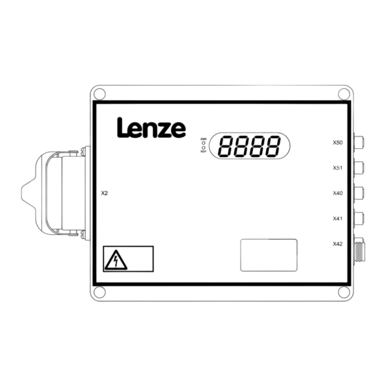
Troubleshooting and fault elimination Status display Troubleshooting and fault elimination Status display Pos. LED Colou Status Description No fault flashing Fault active green on Device enabled flashing Device inhibited CCU210_002F LED display: drive status 4−digit 7−segment display for error messages, warning signals, and status messages LDEDS−CCU210B EN 4.0... - Page 79 Troubleshooting and fault elimination Status display Standard displays Standard displays during operation (C0500 = 0) Pos. Display Description 8. 8. 8. 8. Power−up display for 0.5 s 4 Software version for 0.5 s 8 Error message (blinking) 8 Warning signal (blinking) Controller inhibit active (C0040) ON/OFF switch in OFFposition Parameters are saved in the EEPROM...
- Page 80 − 8. 8. 8. 8. User−specific display Codes for parameter setting Code Possible settings Description ñò < Byte Lenze Selection ^ 80 C0500 Display code for 7−segment display Standard display Drive frequency with sign [Hz] DC−bus voltage [V] Motor current [A] Output stage temperature [°C]...
-
Page 81: Fault Messages
The first error is always saved in C0168/10. ƒ Codes for parameter setting Code Possible settings Description ñò < Byte Lenze Selection C0160 No. of the current warning signal C0161 No. of the current error message C0167 Fault memory (C0168, C0169) and limit value memory (C0183−C0196) - Page 82 Troubleshooting and fault elimination Fault messages Code Possible settings Description ñò < Byte Lenze Selection C0169 Error memory: times of the 10 errors that occurred last {min} 7884000 Time error 1 (latest) Time error 2 Time error 3 Time error 4...
- Page 83 Connect PTC or thermal contact or switch off monitoring with C0120 = 0. Frequency inverter: parameter error Inconsistency within the parameters Load Lenze setting F008 of the frequency inverter, e. g. Transfer parameter data again. because the external data memory...
- Page 84 Troubleshooting and fault elimination Fault messages Display1 Fault Cause Remedy Control system: internal system error Various 1. Transfer parameter data again. F021 Thereby always wait until the PAr message goes out. Only then switch off the voltage. 2. Switch off mains voltage and then switch it on again.
-
Page 85: Appendix
Appendix Signal processing − overview Appendix 10.1 Signal processing − overview Signal processing without HWC function Drive function Manipulation logic Motor control allocation logic V/f-characteristic configuration C0015, C0016, C0017, C0018 C0024, C0029 Motor V1 SS1f C0410/1 C0011/1, C0012/1 SS1p X2.1 C0013/1 Motor V2 SS1n... - Page 86 Appendix Signal processing − overview Signal processing with HWC function C0251 Range HWC>=C0251/1 HWC<=C0251/2 HWC1 Dr i ve f unct i on HWC2 al l ocat i on l ogi c HWC3 HWC4 HWC5 … HWC16 C0244/ 1 HW C Li nk l ogi c Match C0245/ 1 HWC-OR1...
-
Page 87: Code Table
Internally in the Flash memory Externally in the data connector Byte Data length in bytes Possible settings Lenze Setting at delivery Setting after loading the Lenze setting with C0002 = 1 Selection 99 Minimum value {Unit} Maximum value Description Short description of the code... - Page 88 Appendix Code table Code Possible settings Description ñò < Byte Lenze Selection ^ 52 C0011 Drive frequency for ... 1 RW {Hz} 120.0 ... V1 ... V2 ... V3 ... V4 ... V5 ... V6 ... V7 ... V8 ^ 52 C0012 Acceleration time for ...
- Page 89 Appendix Code table Code Possible settings Description ñò < Byte Lenze Selection ^ 41 C0018 Switching frequency of the inverter in ... 1 RW 8 kHz ... Parameter set 1 8 kHz ... Parameter set 2 Possible values 2 kHz...
- Page 90 Appendix Code table Code Possible settings Description ñò < Byte Lenze Selection ^ 64 C0120 Configuration of motor temperature monitoring Error Warning ^ 61 C0121 Tripping class for I xt monitoring Tripping class CLASS 10A Tripping class CLASS 10 Tripping class CLASS 20...
- Page 91 Appendix Code table Code Possible settings Description ñò < Byte Lenze Selection C0161 No. of the current error message C0167 Fault memory (C0168, C0169) and limit value memory (C0183−C0196) [PWD] are deleted if: the service password has been entered in C0007 and C0167 is set to "1".
- Page 92 Appendix Code table Code Possible settings Description ñò < Byte Lenze Selection ^ 75 C0186 Limit values of the output stage temperature {°C} 255 Minimum Maximum ^ 75 C0196 Average output stage temperature {°C} C0200 Software ID (1 string) 82S8219V_xyz00...
- Page 93 Appendix Code table Code Possible settings Description ñò < Byte Lenze Selection ^ 70 C0244 HWC match codes 1 RW 201 HWC match code 1 HWC match code 2 HWC match code 3 HWC match code 4 HWC match code 5...
- Page 94 Appendix Code table Code Possible settings Description ñò < Byte Lenze Selection ^ 70 C0257 HWC control limitation (± of setpoint frequency) {Hz} 10.0 ^ 70 C0258 HWC maximum system deviation {mm} 5000 ^ 70 C0261 1000 Encoder constant {inc/m}...
- Page 95 Appendix Code table Code Possible settings Description ñò < Byte Lenze Selection ^ 63 C0403 Deceleration of non−equivalence detection 1 RW {ms} 10000 Deceleration for C0402/1 Deceleration for C0402/2 Deceleration for C0402/3 Deceleration for C0402/4 ^ 42 C0406 Switch−on delay of digital input signals LOW ð...
- Page 96 Appendix Code table Code Possible settings Description ñò < Byte Lenze Selection ^ 42 C0408 Level inversion for digital inputs à inputs are LOW−active Add values of the inverted inputs: Possible values e. g. DIN1, DIN3 and DIN5 are No inversion LOW−active à...
- Page 97 Appendix Code table Code Possible settings Description ñò < Byte Lenze Selection ^ 44 C0409 Logic operations of digital input signals Link ORx = OR operation Link ANDx = AND operation 1 RW 65535 Link OR1 Link OR2 Link OR3...
- Page 98 Appendix Code table Code Possible settings Description ñò < Byte Lenze Selection ^ 46 C0410 Linking digital input signals to an internal device function ... 1 RW Not assigned ... Motor V1 (incl. brake) Not assigned ... Motor V2 (incl. brake) Not assigned ...
- Page 99 Appendix Code table Code Possible settings Description ñò < Byte Lenze Selection ^ 46 C0410 (Continuation) Linking digital input signals to an internal device function ... Possible values Not assigned DIN1 Digital input DIN1 DIN2 Digital input DIN2 DIN3 Digital input DIN3...
- Page 100 Appendix Code table Code Possible settings Description ñò < Byte Lenze Selection ^ 46 C0410 (Continuation) Linking digital input signals to an internal device function HWC match code 1 HWC match code 1 HWC match code 2 HWC match code 2...
- Page 101 Appendix Code table Code Possible settings Description ñò < Byte Lenze Selection ^ 50 C0415 Linking internal status signals to digital output signal ... 1 RW Not assigned ...Digital output DOUT1 Not assigned ...Digital output DOUT2 Not assigned Reserved Not assigned...
- Page 102 Appendix Code table Code Possible settings Description ñò < Byte Lenze Selection ^ 50 C0415 (Continuation) Linking internal status signals to digital output signal ... Possible values Motor is running Reserved Status On/Off: OFF active Status On/Off: OFF active or fault...
- Page 103 Appendix Code table Code Possible settings Description ñò < Byte Lenze Selection ^ 49 C0416 Level inversion for digital outputs à outputs are LOW−active Add values of the inverted outputs: Possible values e. g. DOUT1 and message bar1 No inversion negative half wave are LOW−active...
- Page 104 Appendix Code table Code Possible settings Description ñò < Byte Lenze Selection Deceleration ramp Vx ð V0 for ... ^ 54 C0434 1 RW {Hz/s} 255 ... Stop 1 ... Stop 2 ... Stop 3 ... Stop 4 ^ 55 C0440 Configuration of function ...
- Page 105 Appendix Code table Code Possible settings Description ñò < Byte Lenze Selection ^ 56 C0451 "Open brake" function: maximum activation time 1000 C0451 = 0 s: – Brake opens if C0410/15 = HIGH – Brake closes if C0410/15 = LOW C0451 >...
- Page 106 Appendix Code table Code Possible settings Description ñò < Byte Lenze Selection ^ 57 C0469 SensoPart step monitoring: Step monitoring inactive Step monitoring active ^ 57 C0470 SensoPart step monitoring: 20 Error delay ^ 57 C0472 SensoPart: distance for switch−over to approach speed ...
- Page 107 Appendix Code table Code Possible settings Description ñò < Byte Lenze Selection ^ 66 C0491 IrDA positioning approach path {mm} 2000 ^ 66 C0492 IrDA positioning approach speed {Hz} 50.0 ^ 66 C0493 IrDA positioning deceleration time {Hz/s} ^ 66...
- Page 108 Appendix Code table Code Possible settings Description ñò < Byte Lenze Selection C0522 Disposable data memory 32 characters (e. g. for freight ID) 1 RW {ASCII} 255 Character 1 Character 2 Character 3 Character 4 Character 5 Character 31 Character 32...
- Page 109 Appendix Code table Code Possible settings Description ñò < Byte Lenze Selection ^ 75 C0602 Status of logic operations (bit coded) 65535 OR operations Bit 0 Status link OR1 Bit 1 Status link OR2 Bit 2 Status link OR3 Bit 3...
- Page 110 © 09/2012 Lenze Drives GmbH Service Lenze Service GmbH Postfach 10 13 52 Breslauer Straße 3 D−31763 Hameln D−32699 Extertal Germany Germany +49 (0)51 54 / 82−0 00 80 00 / 24 4 68 77 (24 h helpline) Ê Ê...
Need help?
Do you have a question about the LDEC Series and is the answer not in the manual?
Questions and answers