Table of Contents
Advertisement
www.belimo.eu
Product information
Adaptive VAV control system
for sensitive working areas
Table of Contents
Technical data sheets
VFP-.. static differential pressure sensors for neutral to slightly aggressive gases
Product information S4-VRP-M VAV • en • v2.0 • 11.2006 • Subject to changes
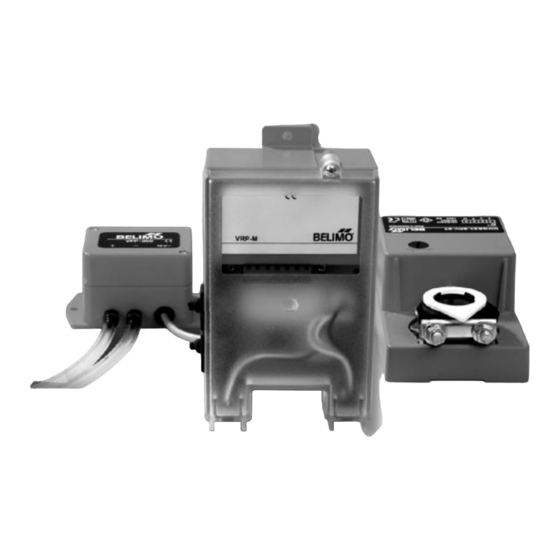
VRP-M VAV system
MP
BUS
®
TECHNOLOGY BY BELIMO
2
3
7
8
9
12
13
15
16
19
21
23
25
1 / 28
Advertisement
Table of Contents

Related Manuals for Belimo VRP-M


Summary of Contents for Belimo VRP-M
-
Page 1: Table Of Contents
VFP-.. static differential pressure sensors for neutral to slightly aggressive gases Fast-running damper actuator for VRP-M system solution NMQB24-SRV-ST Damper actuator for VRP-M system solution NM24A-V-ST Dimensions www.belimo.eu 1 / 28 Product information S4-VRP-M VAV • en • v2.0 • 11.2006 • Subject to changes... -
Page 2: Overview Of The System
< 5 s 110 ... 150 s Power supply From VRP-M From VRP-M VRP-M connection Ready to connect Ready to connect VAV functions 2 / 28 www.belimo.eu Product information S4-VRP-M VAV • en • v2.0 • 11.2006 • Subject to changes... -
Page 3: System Description
The actual value x is compared with the setpoint w set on the VAV controller and the connected damper actuator is controlled according to the resulting system deviation. The VRP-M controller can be controlled according to its function as a CAV constant controller (... - Page 4 / OPEN / bus operation Bus function Up to eight Belimo MP devices (VRP-M / VAV-Compact / damper actuator / valve) can be con- nected via the MP-Bus and integrated into the following systems: – DDC controller with integrated MP-Bus protocol –...
- Page 5 (AC/DC 24 V) and 4 (MP signal) to accessible terminals (floor distributor, control cabinet, etc.), in order to simplify access with the VRP-M-Tool for diagnostic and service work. www.belimo.eu 5 / 28 Product information S4-VRP-M VAV • en • v2.0 • 11.2006 • Subject to changes...
- Page 6 – The VAV / CAV unit must be mounted Prerequisites – The VRP-M system solution must have been set and calibrated for the VAV / CAV unit by the unit manufacturer – The electrical connection must have been made and checked –...
-
Page 7: Vrp-M Adaptive, Digital Pid Vav Controller
* See «Creep flow limitation and minimum setting limit», page 9 ** Not available with DC 24 V supply *** For bus operation, see pages 16...18 www.belimo.eu 7 / 28 Product information S4-VRP-M VAV • en • v2.0 • 11.2006 • Subject to changes... -
Page 8: Application
• The device does not contain any parts that can be replaced or repaired by the user. • The manufacturer of the VAV unit (OEM) is responsible for ensuring that the VRP-M- controller is installed and set correctly as well as for the overall precision of the VAV unit. If replacement devices are ordered, they are configured by the OEM at the factory according to the installed system. -
Page 9: Functions
Optimum range Setting with restriction Setting with greatest restriction Reference signal w Creep flow limitation <2 Pa Unit manufacturer’s minimum setting limit www.belimo.eu 9 / 28 Product information S4-VRP-M VAV • en • v2.0 • 11.2006 • Subject to changes... - Page 10 The operating mode control signals are connected to inputs 6 (z1) and 7 (z2). If signals appear at these two inputs simultaneously, input 6 (z1) for the OPEN function takes priority. 10 / 28 www.belimo.eu Product information S4-VRP-M VAV • en • v2.0 • 11.2006 • Subject to changes...
- Page 11 6 (z1) / 7 (z2) Terminal Priority Function OPEN CLOSED / / / … www.belimo.eu 11 / 28 Product information S4-VRP-M VAV • en • v2.0 • 11.2006 • Subject to changes...
-
Page 12: System Configuration
Calibration – The values are specified and fixed-programmed by the unit manufacturer. Each VRP-M system solution is optimally adapted to the VAV unit by means of the setting. corresponds to the maximum volumetric flow of the VAV unit at which the pressure drop and noise are still within the permissible operating conditions. -
Page 13: Operating Data Settings (With Vrp-M-Tool)
(mode setting – voltage range) directly on the system if necessary. The VRP- M-Tool adapter must be connected to the diagnostics socket on the VRP-M or to the MP connec- tion routed to the terminals for this purpose (see Note on page 15). - Page 14 DC 2.0 ... 10 V VRP-M-Tool – Availability The current version of the VRP-M-Tool and the associated documentation can be downloaded from www.belimo.eu. 14 / 28 www.belimo.eu Product information S4-VRP-M VAV • en • v2.0 • 11.2006 • Subject to changes...
-
Page 15: Connection Of The Vrp-M-Tool
MP connection (terminal 4). A level converter is required for communication, e.g.: ZIP-RS232. Conventional operation (PP) VRP-M runs with a locally connected reference signal (0 ... 10 V on connection 3). VRP-M detects that there is no tool connected and switches back to the connected analogue reference signal automatically after 120 s. -
Page 16: Bus Operation
2...8 s, depending on the number of connected bus users and integrated sensors. The local VRP-M control function is not affected by the cycle time. The cycle time of the MP-Bus must always be taken into account, however, when selecting setpoints via the MP-Bus. - Page 17 Bus fail function Last setpoint The VRP-M saves the current setpoint, i.e. the last setpoint to have been received from a bus master (VRP-M-Tool, UK24LON). If the MP network fails, the connected VRP-M detects this and retains this setpoint until it receives a new one from the MP master.
- Page 18 – VAV-Compact NMV-D2-MP Product Information – Bus and communication systems section Addressing If the VRP-M system solution is integrated in a bus system, each connected VRP-M must be assigned an MP address in the range 1 ... 8. Procedure – Start the addressing procedure on the MP-Bus master with the VRP-M-Tool, UK24LON, etc.
-
Page 19: Vfp
• The devices contain electrical and electronic components and are not allowed to be disposed of as household refuse. All locally valid regulations and requirements must be observed. www.belimo.eu 19 / 28 Product information S4-VRP-M VAV • en • v2.0 • 11.2006 • Subject to changes... - Page 20 VFP-.. Static differential pressure sensors Product features Together with a VRP-M controller and a Belimo NM..-ST actuator, the VFP-.. static pressure Application sensors form a control system for pressure-independent variable (VAV) and constant (CAV) air volume controls. The pressure sensors are used for static differential pressure measurement with differential pressure pickups installed in air ducts.
-
Page 21: Fast-Running Damper Actuator For Vrp-M System Solution Nmqb24-Srv-St
• The device contains electrical and electronic components and is not allowed to be disposed of as household refuse. All locally valid regulations and requirements must be observed. www.belimo.eu 21 / 28 Product information S4-VRP-M VAV • en • v2.0 • 11.2006 • Subject to changes... - Page 22 High functional reliability stop is reached. Electrical installation The ready-to-connect actuator unit is connected to the VRP-M controller with the 6-pin plug. 22 / 28 www.belimo.eu Product information S4-VRP-M VAV • en • v2.0 • 11.2006 • Subject to changes...
-
Page 23: Damper Actuator For Vrp-M System Solution Nm24A-V-St
• When the required torque is calculated, the cross section, design and installation site as well as the air flow conditions must be observed. www.belimo.eu 23 / 28 Product information S4-VRP-M VAV • en • v2.0 • 11.2006 • Subject to changes... - Page 24 The local and currently valid regulations and requirements must be observed. Product features The actuator is controlled with a Belimo VRP-M controller and travels to the position Mode of operation defined by the control signal. Simple direct mounting on the damper spindle with a universal spindle clamp, supplied with an Simple direct mounting anti-rotation strap to prevent the actuator from rotating.
-
Page 25: Dimensions
Damper spindle Length Clamp, top min. 40 8 ... 26,7 Clamp, bottom * min. 20 8 ... 20 * Option (accessorie K-NA) www.belimo.eu 25 / 28 Product information S4-VRP-M VAV • en • v2.0 • 11.2006 • Subject to changes... - Page 26 Notes 26 / 28 www.belimo.eu Product information S4-VRP-M VAV • en • v2.0 • 11.2006 • Subject to changes...
- Page 28 Guarantee Worldwide present Complete assortment from a single source Examined Quality Short delivery time Comprehensive support Headquarters Subsidiaries, Representatives and Agencies BELIMO Holding AG Agentina Denmark Lebanon Rumania Brunnenbachstrasse 1 Australia Egypt Liechtenstein Russia CH-8340 Hinwil Bahrain Estonia Lithuania Saudi Arabia Tel.
Need help?
Do you have a question about the VRP-M and is the answer not in the manual?
Questions and answers