Advertisement
Quick Links
VC 1100
1
Overview
2
Technical Data
3
Connectors and Interfaces
4
Built-in Operating Panel and Display
5
List of Setup Parameters
6
Installation and Commissioning
VC1100E/contents
© Schenck VIBRO GmbH, D-64273 Darmstadt, November 97
Contents
VIBROCONTROL 1100
C01 / C02 / C11 / C12
Version 2 →
C01 / C02 - C11 / C12
CONTENTS
1
Advertisement

Summary of Contents for Schenck Vibrocontrol 110 C01
- Page 1 C01 / C02 / C11 / C12 Overview Technical Data Connectors and Interfaces Built-in Operating Panel and Display Error messages List of Setup Parameters Installation and Commissioning Version 2 → VC1100E/contents © Schenck VIBRO GmbH, D-64273 Darmstadt, November 97 C01 / C02 - C11 / C12...
- Page 2 Apart from the bearing condition, which is not applicable to the instrument types C11 and C12, the descriptions for all instruments are the same. Version 2 → contents/VC1100E C01 / C02 - C11 / C12 © Schenck VIBRO GmbH, D-64273 Darmstadt, November 97...
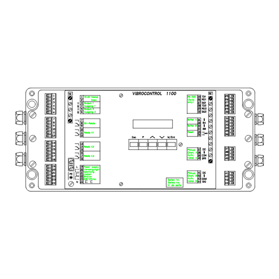
- Page 3 The wiring is done through removable terminal strip connectors. Vibration analyzers or data collectors can be connected to the buffered outputs without interrupting the monitoring functions. Version 2 → VC1100E/overview © Schenck VIBRO GmbH, D-64273 Darmstadt, November 97 C01 / C02 - C11 / C12...
-
Page 4: Measured Values
BCU limit value. If for instance the measuring result is divided by two due to the scaling factor, also the limit value must be divided by two. Version 2 → overview//VC1100E C01 / C02 - C11 / C12 © Schenck VIBRO GmbH, D-64273 Darmstadt, November 97... - Page 5 After the parameter input of all scaling factors, the re-spective measuring point must display the desired BCU initial value. Version 2 → VC1100E/overview © Schenck VIBRO GmbH, D-64273 Darmstadt, November 97 C01 / C02 - C11 / C12...
- Page 6 The averaging be switched on and off separately for channel A and channel B (parameters J15 ... J18). Version 2 → overview//VC1100E C01 / C02 - C11 / C12 © Schenck VIBRO GmbH, D-64273 Darmstadt, November 97...
- Page 7 The measuring ranges for BCU-Monitoring are independent of the measuring ranges for vibration monitoring. Measured Parameter Measuring Range Unit Bearing Condition 0 ... 1.00 0 ... 140 Version 2 → VC1100E/overview © Schenck VIBRO GmbH, D-64273 Darmstadt, November 97 C01 / C02 - C11 / C12...
- Page 8 The built-in signal conditioners are microprocessor controlled. Gain factors, filters, and the integrator are set automatically. The settings are determined by the microprocessor from the configuration. Version 2 → overview//VC1100E C01 / C02 - C11 / C12 © Schenck VIBRO GmbH, D-64273 Darmstadt, November 97...
- Page 9 Outside the measuring times, the current display values of the other channel are frozen, the current measured value, however, is monitored in intervals of 0.25 seconds. Version 2 → VC1100E/overview © Schenck VIBRO GmbH, D-64273 Darmstadt, November 97 C01 / C02 - C11 / C12...
- Page 10 Detector, the measurement of Bearing Condition is indepen- dent of the vibration measurement. The settling time is 2.75 s and the measuring time is 1.25 s. Version 2 → overview//VC1100E C01 / C02 - C11 / C12 © Schenck VIBRO GmbH, D-64273 Darmstadt, November 97...
- Page 11 At this point the alarm event is acknowledged. In case 2 the alarm delay time is prolonged by the measurement cycle of the other channel. Version 2 → VC1100E/overview © Schenck VIBRO GmbH, D-64273 Darmstadt, November 97 C01 / C02 - C11 / C12...
- Page 12 The Log Book is deleted every time the VIBROCONTROL 1100 is powered up. It can also be deleted using the built-in operator panel or via the serial interface. Version 2 → overview//VC1100E 1-10 C01 / C02 - C11 / C12 © Schenck VIBRO GmbH, D-64273 Darmstadt, November 97...
- Page 13 TROL 1100 is disconnected. Mode No Alarm Alarm Normally Energized Relay active Relay not active Normally De-Energized Relay not active Relay active Version 2 → VC1100E/overview © Schenck VIBRO GmbH, D-64273 Darmstadt, November 97 C01 / C02 - C11 / C12 1-11...
- Page 14 Since the OK-Relay is normally energized, the messages are output in the operating state network ON/OFF. Version 2 → overview//VC1100E 1-12 C01 / C02 - C11 / C12 © Schenck VIBRO GmbH, D-64273 Darmstadt, November 97...
- Page 15 (ER -31) – no valid calibration data in the EEPROM (ER -37) a hardware error is present. This error can only be eliminated by a Schenck service station or in the parent company. Version 2 → VC1100E/overview ©...
-
Page 16: Inputs And Outputs
Book, and measured values can be read, stored, displayed, printed, etc. In addition the configuration of each VIBROCONTROL 1100 can be confirmed and modified. Version 2 → overview//VC1100E 1-14 C01 / C02 - C11 / C12 © Schenck VIBRO GmbH, D-64273 Darmstadt, November 97... - Page 17 Beispiel: zero-to-peak value = rms value x 1.41 [pc] peak-to-peak value = rms value x 2.82 [ppc] Version 2 → VC1100E/overview © Schenck VIBRO GmbH, D-64273 Darmstadt, November 97 C01 / C02 - C11 / C12 1-15...
- Page 18 Overview VC 1100 This page has been reserved for your notes. Version 2 → overview//VC1100E 1-16 C01 / C02 - C11 / C12 © Schenck VIBRO GmbH, D-64273 Darmstadt, November 97...
- Page 19 2 x 30 mA short-circuit- proof • EMC Emitted interference according to EN 50081-1 Immunitity from interferences according to EN 50082-2 Version 2 → VC1100E/tedata © Schenck VIBRO GmbH, D-64273 Darmstadt, November 97 C01 / C02 - C11 / C12...
- Page 20 • Operating Temperature Range 0 ... + 50 °C (32 ... 122 °F) • Rel. Humidity max. 95 % non condensing Version 2 → tedata/VC1100E C01 / C02 - C11 / C12 © Schenck VIBRO GmbH, D-64273 Darmstadt, November 97...
-
Page 21: Frequency Range
2) The setup is microprocessor controlled via the built-in operator panel or Remote Interface. 3) The respective selection is made software-controlled in dialog mode. Version 2 → VC1100E/tedata © Schenck VIBRO GmbH, D-64273 Darmstadt, November 97 C01 / C02 - C11 / C12... - Page 22 Bearing Condition 3) The respective selection is made software-controlled in dialog mode. 4) Ranges between min. and max. are infinitely variable. Version 2 → tedata/VC1100E C01 / C02 - C11 / C12 © Schenck VIBRO GmbH, D-64273 Darmstadt, November 97...
- Page 23 0.25 s 3) The respective selection is made software-controlled in dialog mode. 4) Ranges between min. and max. are infinitely variable. Version 2 → VC1100E/tedata © Schenck VIBRO GmbH, D-64273 Darmstadt, November 97 C01 / C02 - C11 / C12...
- Page 24 70 pF/m : ≤ 16 m (Wire against wire) 3) The respective selection is made software-controlled in dialog mode. Version 2 → tedata/VC1100E C01 / C02 - C11 / C12 © Schenck VIBRO GmbH, D-64273 Darmstadt, November 97...
-
Page 25: Limit Values
A spark extinguisher must be installed as close to the spark generator as possible ! 3) The respective selection is made software-controlled in dialog mode. Version 2 → VC1100E/tedata © Schenck VIBRO GmbH, D-64273 Darmstadt, November 97 C01 / C02 - C11 / C12... - Page 26 1200, 2400, 4800 or 9600 Parity none Data Bits 8 Stop Bits 1 3) The respective selection is made software-controlled in dialog mode. Version 2 → tedata/VC1100E C01 / C02 - C11 / C12 © Schenck VIBRO GmbH, D-64273 Darmstadt, November 97...
- Page 27 Power 19 ... 24 Pickup Channel A 37 ... 40 Pickup Channel B 41 ... 44 Relay Reset 35 ... 36 Version 2 → VC1100E/connect © Schenck VIBRO GmbH, D-64273 Darmstadt, November 97 C01 / C02 - C11 / C12...
- Page 28 Signal Ground (RS-232-C) Buffered Output Channel A Buffered Output Channel B TE (0VA) and 0VD can be connected at a central point. Version 2 → connect/VC1100E C01 / C02 - C11 / C12 © Schenck VIBRO GmbH, D-64273 Darmstadt, November 97...
- Page 29 1100 and its placement in the operating environment. Special care should be taken when installing pickups in hazardous areas. Apply safety standards properly. Version 2 → VC1100E/connect © Schenck VIBRO GmbH, D-64273 Darmstadt, November 97 C01 / C02 - C11 / C12...
-
Page 30: Power Supply
PE and TE by removing this jumper wire. Please consult the General Grounding Recommendation in this manual. Version 2 → connect/VC1100E C01 / C02 - C11 / C12 © Schenck VIBRO GmbH, D-64273 Darmstadt, November 97... - Page 31 200 m (600 feet) requires proper installation including appropriate junction boxes and signal cables. For more information, please consult the manual for the pickup used. Version 2 → VC1100E/connect © Schenck VIBRO GmbH, D-64273 Darmstadt, November 97 C01 / C02 - C11 / C12...
- Page 32 Fig. 3 - 4 : Connection of a galvanically free switch to the Relay Reset-Input Version 2 → connect/VC1100E C01 / C02 - C11 / C12 © Schenck VIBRO GmbH, D-64273 Darmstadt, November 97...
- Page 33 ! Fig. 3 - 5 : Connecting the-Relays Figure 3 - 5 shows the contacts in the de-energized position. Version 2 → VC1100E/connect © Schenck VIBRO GmbH, D-64273 Darmstadt, November 97 C01 / C02 - C11 / C12...
- Page 34 The thicker lines show energized circuits. Fig. 3 - 6: Explanation of the Normally De-Energized and Normally Energized Mode for Relays Version 2 → connect/VC1100E C01 / C02 - C11 / C12 © Schenck VIBRO GmbH, D-64273 Darmstadt, November 97...
-
Page 35: Analog Outputs
Current Output: 0/4 ... 20 mA Load Voltage Output: 0 ... 10 V R > 1 kΩ, short-circuit proof Fig. 3 - 7: Connecting Analog Outputs Version 2 → VC1100E/connect © Schenck VIBRO GmbH, D-64273 Darmstadt, November 97 C01 / C02 - C11 / C12... - Page 36 ≤ 16 m of 70 pF/m (Wire against wire) Fig. 3 - 8: Connecting to the Buffered Outputs for On Site Analysis Version 2 → connect/VC1100E 3-10 C01 / C02 - C11 / C12 © Schenck VIBRO GmbH, D-64273 Darmstadt, November 97...
- Page 37 TD = Transmit Data (send) SG = Signal Ground (Ground) Fig. 3 - 10: Interfacing a HOST with one VC 1100 Version 2 → VC1100E/connect © Schenck VIBRO GmbH, D-64273 Darmstadt, November 97 C01 / C02 - C11 / C12 3-11...
- Page 38 Fig. 3 - 11: Interfacing a HOST with several VC-1100’s Use commercially available shielded data transfer cables with two twisted pairs. Version 2 → connect/VC1100E 3-12 C01 / C02 - C11 / C12 © Schenck VIBRO GmbH, D-64273 Darmstadt, November 97...
- Page 39 15 minutes, and the display will be turned off after an additional 15 minutes of inactivity. Version 2 → VC1100E/bult-in © Schenck VIBRO GmbH, D-64273 Darmstadt, November 97 C01 / C02 - C11 / C12...
- Page 40 The last parameter is P02. Exit "Display Setup Parameters" mode and return to the main menu. Version 2 → built-in/VC1100E C01 / C02 - C11 / C12 © Schenck VIBRO GmbH, D-64273 Darmstadt, November 97...
- Page 41 The longer you hold a key down, the faster the parameter numbers change. The last parameter is P02. Access the change parameter value mode by pressing Version 2 → VC1100E/bult-in © Schenck VIBRO GmbH, D-64273 Darmstadt, November 97 C01 / C02 - C11 / C12...
- Page 42 The following parameters I03 Vibration velocity transducer v J05 Unit of the measured parameter g Error messages see explanations on page 16. Version 2 → built-in/VC1100E C01 / C02 - C11 / C12 © Schenck VIBRO GmbH, D-64273 Darmstadt, November 97...
- Page 43 Parameter numbermode is selectable Press to return to the select parameter number mode. Press again to return to the main menu. Version 2 → VC1100E/bult-in © Schenck VIBRO GmbH, D-64273 Darmstadt, November 97 C01 / C02 - C11 / C12...
- Page 44 If not, an error message will appear (see previous page). The consistency check takes about 15 s. During this time the mo- nitoring function is suspended. Version 2 → built-in/VC1100E C01 / C02 - C11 / C12 © Schenck VIBRO GmbH, D-64273 Darmstadt, November 97...
- Page 45 Step to next measured values: − Bearing condition channel A − Vibration level channel B − Bearing condition channel B Relay status Relay identification Event Version 2 → VC1100E/bult-in © Schenck VIBRO GmbH, D-64273 Darmstadt, November 97 C01 / C02 - C11 / C12...
- Page 46 Do not reset relays. Accept reset command and return to display mode. Press , and show Log Book. Step to first Log Book entry. Version 2 → built-in/VC1100E C01 / C02 - C11 / C12 © Schenck VIBRO GmbH, D-64273 Darmstadt, November 97...
- Page 47 Exit the Display measured values mode and return to the main menu. Find an explanation of the Log Book entries and events on pages 14 and 15 of this chapter. Version 2 → VC1100E/bult-in © Schenck VIBRO GmbH, D-64273 Darmstadt, November 97 C01 / C02 - C11 / C12...
- Page 48 Hold down the key, and press the key to enter the service mode.The service functions all start with an S. Version 2 → built-in/VC1100E 4-10 C01 / C02 - C11 / C12 © Schenck VIBRO GmbH, D-64273 Darmstadt, November 97...
- Page 49 Function S04 checks the OK-Relay. OK off : OK-Relay not active. OK on : OK-Relay active. Press to exit the OK-Relay test. Version 2 → VC1100E/bult-in © Schenck VIBRO GmbH, D-64273 Darmstadt, November 97 C01 / C02 - C11 / C12 4-11...
- Page 50 10 to 0 is displayed. OK will appear on the display if the test is completed successfully. The self-test does not suspend the monitoring mode. Version 2 → built-in/VC1100E 4-12 C01 / C02 - C11 / C12 © Schenck VIBRO GmbH, D-64273 Darmstadt, November 97...
- Page 51 ??? to 0, at which time the display returns to: Press to exit self-calibration and return to the main menu. Version 2 → VC1100E/bult-in © Schenck VIBRO GmbH, D-64273 Darmstadt, November 97 C01 / C02 - C11 / C12 4-13...
- Page 52 OK-Relay is active for 15 safter po- wer is returned. OK A OK-Relay is active. Malfunction Channel A OK B OK-Relay is active. Malfunction Channel B Version 2 → built-in/VC1100E 4-14 C01 / C02 - C11 / C12 © Schenck VIBRO GmbH, D-64273 Darmstadt, November 97...
- Page 53 RESET DIALOG Relay reset via built-in operator panel RESET EXTERN Relay reset via reset input RESET RS-232 Relay reset via Remote-I/O Version 2 → VC1100E/bult-in © Schenck VIBRO GmbH, D-64273 Darmstadt, November 97 C01 / C02 - C11 / C12 4-15...
-
Page 54: Error Messages
Therefore, a parameter other than the one displayed could be the cause of the inconsistency. A list of error messages appears on the next page. Version 2 → built-in/VC1100E 4-16 C01 / C02 - C11 / C12 © Schenck VIBRO GmbH, D-64273 Darmstadt, November 97... - Page 55 No valid configuration stored in EEPROM. (Re-configure) / Hardware error If no valid configuration can be made, a hardware error is present. Version 2 → VC1100E/bult-in © Schenck VIBRO GmbH, D-64273 Darmstadt, November 97 C01 / C02 - C11 / C12 4-17...
- Page 56 (J03/J04); e.g. vibration displacement cannot be measu- red in g. The selected measuring range (J09/J10; J13/J14) is too small or too large. Version 2 → built-in/VC1100E 4-18 C01 / C02 - C11 / C12 © Schenck VIBRO GmbH, D-64273 Darmstadt, November 97...
- Page 57 (I03) has been selected. Parameter transfer is not possible since presently another transfer is made or the self-calibration is running. Repeat the command! Version 2 → VC1100E/bult-in © Schenck VIBRO GmbH, D-64273 Darmstadt, November 97 C01 / C02 - C11 / C12 4-19...
- Page 58 Re-do configuration or download consistent setup. If this is not successful, send unit to SCHENCK for repair. Repeat command using correct data. Version 2 → built-in/VC1100E 4-20 C01 / C02 - C11 / C12 © Schenck VIBRO GmbH, D-64273 Darmstadt, November 97...
- Page 59 "Parameter Specifier" consists of a group and a number within the group. The first character specifies the group and the two digit number specifies the individual parameter. Version 2 → VC1100E/paralist © Schenck VIBRO GmbH, D-64273 Darmstadt, Juni 98 C01 / C02 - C11 / C12...
- Page 60 Define device address and baud rate. Group S Service Functions Check relay operation. Set analog outputs to predefined levels. Run self-test and Self-calibration. Version 2 → parqalist/VC1100E C01 / C02 - C11 / C12 © Schenck VIBRO GmbH, D-64273 Darmstadt, Juni 98...
- Page 61 The following is a list of the symbols that are used in the block diagrams, and their meaning. Symbols Fig. 5 - 1: Legend Version 2 → VC1100E/paralist © Schenck VIBRO GmbH, D-64273 Darmstadt, Juni 98 C01 / C02 - C11 / C12...
- Page 62 List of Setup Parameters VC 1100 This page has been reserved for your notes. Version 2 → parqalist/VC1100E C01 / C02 - C11 / C12 © Schenck VIBRO GmbH, D-64273 Darmstadt, Juni 98...
- Page 63 For measured value acquisition, connect a pickup to channel A. I01 = N : Disables all measuring and monitoring functions for channel A. Version 2 → VC1100E/paralist © Schenck VIBRO GmbH, D-64273 Darmstadt, Juni 98 C01 / C02 - C11 / C12...
- Page 64 VIBROCONTROL 1100 ge- nerates error-message: -58. Select mV/g or mV/m/s for accelerometers mV/mm/s or mV/ips for vibration velocity transducers. Version 2 → parqalist/VC1100E C01 / C02 - C11 / C12 © Schenck VIBRO GmbH, D-64273 Darmstadt, Juni 98...
- Page 65 Frequency response linearization is not active At a switch-on of the frequency response linearization, the Schenck vibration velocity pickup supplies an exact measurement even in low frequency ranges, e.g. measurements below the natu- ral frequency of the pickup(f < 8 Hz or f <...
- Page 66 List of Setup Parameters VC 1100 This page has been reserved for your notes. Version 2 → parqalist/VC1100E C01 / C02 - C11 / C12 © Schenck VIBRO GmbH, D-64273 Darmstadt, Juni 98...
- Page 67 The range is conti- nuously adjustable within the minimum and maximum values shown in the table. Version 2 → VC1100E/paralist © Schenck VIBRO GmbH, D-64273 Darmstadt, Juni 98 C01 / C02 - C11 / C12...
- Page 68 0... 6.00 0... 40.0 Bearing condition (BEARCON) 0... 1.00 0...140 Fig. 5 - 4: Parameter Group J, Signal Detection Type Version 2 → parqalist/VC1100E 5-10 C01 / C02 - C11 / C12 © Schenck VIBRO GmbH, D-64273 Darmstadt, Juni 98...
- Page 69 Choises : a, v, s Function : Define the measured vibration parameter for channel B Vibration acceleration Vibration velocity Vibration displacement Version 2 → VC1100E/paralist © Schenck VIBRO GmbH, D-64273 Darmstadt, Juni 98 C01 / C02 - C11 / C12 5-11...
- Page 70 If the unit does not match the selected measured parameter (J04), the consistency check generates the error-message - 61. Version 2 → parqalist/VC1100E 5-12 C01 / C02 - C11 / C12 © Schenck VIBRO GmbH, D-64273 Darmstadt, Juni 98...
- Page 71 B. You can use diffe- rent full scale values for channel A and B. For more information see parameter J09 Version 2 → VC1100E/paralist © Schenck VIBRO GmbH, D-64273 Darmstadt, Juni 98 C01 / C02 - C11 / C12 5-13...
- Page 72 You can use different full scale values for channel A and B. If you enter values outside the defined range, the consistency check ge- nerates error-message: -62. Version 2 → parqalist/VC1100E 5-14 C01 / C02 - C11 / C12 © Schenck VIBRO GmbH, D-64273 Darmstadt, Juni 98...
- Page 73 10 ... 3600 Dimension Seconds Function Define time constant for BCU averaging chan- nel B. Condition Averaging channel B (J16) = active. Version 2 → VC1100E/paralist © Schenck VIBRO GmbH, D-64273 Darmstadt, Juni 98 C01 / C02 - C11 / C12 5-15...
- Page 74 Factor Function Setting of all BCU measuring points to the same initial value by means of the BCU scaling factor. Version 2 → parqalist/VC1100E 5-16 C01 / C02 - C11 / C12 © Schenck VIBRO GmbH, D-64273 Darmstadt, Juni 98...
- Page 75 10 Hz ISO Lower frequency corner special Lower frequency corner ∗ Possible only if a supplementary filter is installed as an option. Version 2 → VC1100E/paralist © Schenck VIBRO GmbH, D-64273 Darmstadt, Juni 98 C01 / C02 - C11 / C12 5-17...
- Page 76 10 kHz Upper frequency corner special Upper frequency corner ∗ Possible only if a supplementary filter is installed as an option. Version 2 → parqalist/VC1100E 5-18 C01 / C02 - C11 / C12 © Schenck VIBRO GmbH, D-64273 Darmstadt, Juni 98...
- Page 77 Signal Range Choises : 0 ... 10 V, 0 ... 20 mA, 4 ... 20 mA Function : Select signal type. Version 2 → VC1100E/paralist © Schenck VIBRO GmbH, D-64273 Darmstadt, Juni 98 C01 / C02 - C11 / C12 5-19...
- Page 78 In connection with an indicator or a plotter, the ana- log output can be scaled to an optional full scale value within the present range limits. Version 2 → parqalist/VC1100E 5-20 C01 / C02 - C11 / C12 © Schenck VIBRO GmbH, D-64273 Darmstadt, Juni 98...
- Page 79 After removing the OK error and acknowledging it by "Relay reset", they perform their normal function again. Fig. 5 - 6 : Parameter Group M, Limit Value Configuration Version 2 → VC1100E/paralist © Schenck VIBRO GmbH, D-64273 Darmstadt, Juni 98 C01 / C02 - C11 / C12 5-21...
- Page 80 Enable or disable monitoring of limit value lim_1 B. Y = Monitoring lim_1 B. N = Do not monitoring lim_1 B. Version 2 → parqalist/VC1100E 5-22 C01 / C02 - C11 / C12 © Schenck VIBRO GmbH, D-64273 Darmstadt, Juni 98...
- Page 81 Enable or disable monitoring of limit value lim_b (BCU channel B). Y = Monitoring lim_b. N = Do not monitoring lim_b. Version 2 → VC1100E/paralist © Schenck VIBRO GmbH, D-64273 Darmstadt, Juni 98 C01 / C02 - C11 / C12 5-23...
- Page 82 Resolution 0.020 ... 0.999 1.00 9.99 10.0 99.9 Function Enter limit value lim_2 B in the measured para- meter units. Version 2 → parqalist/VC1100E 5-24 C01 / C02 - C11 / C12 © Schenck VIBRO GmbH, D-64273 Darmstadt, Juni 98...
- Page 83 Channel B : Alarm Delay Time lim_1 Choises 1 ... 99 Dimension Seconds Function Define alarm delay time for channel B lim_1. Version 2 → VC1100E/paralist © Schenck VIBRO GmbH, D-64273 Darmstadt, Juni 98 C01 / C02 - C11 / C12 5-25...
- Page 84 Channel B : Alarm Delay Time lim_b Choises 3 ... 99 Dimension Seconds Function Define alarm delay time for channel B lim_b. Version 2 → parqalist/VC1100E 5-26 C01 / C02 - C11 / C12 © Schenck VIBRO GmbH, D-64273 Darmstadt, Juni 98...
- Page 85 It is common to assign alarm levels lim_1 of channel A and B to relay K1 and alarm levels lim_2 of channel A and B to relay K2. Version 2 → VC1100E/paralist © Schenck VIBRO GmbH, D-64273 Darmstadt, Juni 98 C01 / C02 - C11 / C12 5-27...
- Page 86 K1 = lim_1B controls relay K1 K2 = lim_1B controls relay K2 K3 = lim_1B controls relay K3 Version 2 → parqalist/VC1100E 5-28 C01 / C02 - C11 / C12 © Schenck VIBRO GmbH, D-64273 Darmstadt, Juni 98...
- Page 87 K1 = lim_bB controls relay K1 K2 = lim_bB controls relay K2 K3 = lim_bB controls relay K3 Version 2 → VC1100E/paralist © Schenck VIBRO GmbH, D-64273 Darmstadt, Juni 98 C01 / C02 - C11 / C12 5-29...
- Page 88 Select normally energized or normally de-energized mode for relay K1 Y = Relay K1 operates normally energized. N = Relay K1 operates normally de-energized. Version 2 → parqalist/VC1100E 5-30 C01 / C02 - C11 / C12 © Schenck VIBRO GmbH, D-64273 Darmstadt, Juni 98...
- Page 89 Exceedance of at least one of the assigned alarm levels trips relay K3. Only exceedance of all assigned alarm levels trips relay K3. Version 2 → VC1100E/paralist © Schenck VIBRO GmbH, D-64273 Darmstadt, Juni 98 C01 / C02 - C11 / C12 5-31...
- Page 90 List of Setup Parameters VC 1100 This page has been reserved for your notes. Version 2 → parqalist/VC1100E 5-32 C01 / C02 - C11 / C12 © Schenck VIBRO GmbH, D-64273 Darmstadt, Juni 98...
- Page 91 Y = OK monitoring for pickup channel B is active N = OK monitoring for pickup channel B is not active Version 2 → VC1100E/paralist © Schenck VIBRO GmbH, D-64273 Darmstadt, Juni 98 C01 / C02 - C11 / C12 5-33...
- Page 92 OK-lower value, an OK error message is displayed. The typical setting values for the OK-upper limit and the OK-lower limit are dependent on the transducer type. For SCHENCK trans- ducers the following settings are recommended: Velocity transducer (series VS - ...)
- Page 93 1200 Baud rate: 1200 Bd 2400 Baud rate: 2400 Bd 4800 Baud rate: 4800 Bd 9600 Baud rate: 9600 Bd Version 2 → VC1100E/paralist © Schenck VIBRO GmbH, D-64273 Darmstadt, Juni 98 C01 / C02 - C11 / C12 5-35...
- Page 94 List of Setup Parameters VC 1100 This page has been reserved for your notes. Version 2 → parqalist/VC1100E 5-36 C01 / C02 - C11 / C12 © Schenck VIBRO GmbH, D-64273 Darmstadt, Juni 98...
-
Page 95: Analog Output Test
If the self-test detects an error, the error message is displayed for x seconds and automati- cally restarts the system. The error message is stored in the Log Book. Version 2 → VC1100E/paralist © Schenck VIBRO GmbH, D-64273 Darmstadt, Juni 98 C01 / C02 - C11 / C12 5-37... - Page 96 OK on, OK off Funktion : Test OK-relay. OK on = OK-Relay is active OK off = OK-Relay is not active Version 2 → parqalist/VC1100E 5-38 C01 / C02 - C11 / C12 © Schenck VIBRO GmbH, D-64273 Darmstadt, Juni 98...
- Page 97 4 mA = The output current is 4 mA 12 mA = The output current is 12 mA 20 mA = The output current is 20 mA Version 2 → VC1100E/paralist © Schenck VIBRO GmbH, D-64273 Darmstadt, Juni 98 C01 / C02 - C11 / C12 5-39...
- Page 98 S 09 TEST Function : Start self-test of VIBROCONTROL 1100. S 10 CALIBRATION Function : Start self-calibration of VIBROCONTROL 1100. Version 2 → parqalist/VC1100E 5-40 C01 / C02 - C11 / C12 © Schenck VIBRO GmbH, D-64273 Darmstadt, Juni 98...
- Page 99 Analog Output 1: Full Scale [______________] Analog Output 2: Full Scale [______________] ∗ Possible only if a supplementary filter is installed as an option. Version 2 → VC1100E/paralist © Schenck VIBRO GmbH, D-64273 Darmstadt, Juni 98 C01 / C02 - C11 / C12 5-41...
- Page 100 2400 [ ] 1200 [ ] P02 Serial Port 2: 9600 [ ] 4800 [ ] 2400 [ ] 1200 [ ] Version 2 → parqalist/VC1100E 5-42 C01 / C02 - C11 / C12 © Schenck VIBRO GmbH, D-64273 Darmstadt, Juni 98...
- Page 101 OK error must clear show- ing everything is configured correctly. Connect peripheral devices to relays and analog outputs. Connect serial interfaces as required Version 2 → VC1100E/mounting © Schenck VIBRO GmbH, D-64273 Darmstadt, November 97 C01 / C02 - C11 / C12...
- Page 102 (S10). Recommendation Run auto-calibration under operating conditions with the machi- nery running. The auto-calibration function does not change setup parameters. Version 2 → mounting/VC1100E C01 / C02 - C11 / C12 © Schenck VIBRO GmbH, D-64273 Darmstadt, November 97...
Need help?
Do you have a question about the Vibrocontrol 110 C01 and is the answer not in the manual?
Questions and answers