Advertisement
Quick Links
W O R K
A R E A
P R O T E C T I O N
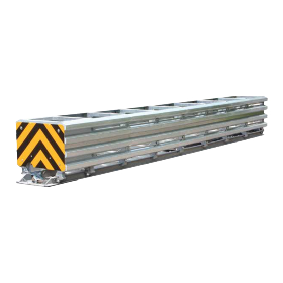
SCI70GM AND SCI100GM
DESIGN & INSTALLATION MANUAL
The World's Only
Speed-Dependent
Crash Attenuator
SMART CUSHION
INNOVATIONS
®
MASH and
N C H R P 3 5 0 A p p r o v e d
Corporate Office:
2500 Production Drive
St. Charles, Il 60174
•
Telephone: 800-327-4417
workareaprotection.com
Advertisement

Summary of Contents for Work Area Protection SMART CUSHION INNOVATIONS SCI70GM
- Page 1 W O R K A R E A P R O T E C T I O N SCI70GM AND SCI100GM DESIGN & INSTALLATION MANUAL The World’s Only Speed-Dependent Crash Attenuator SMART CUSHION INNOVATIONS ® MASH and N C H R P 3 5 0 A p p r o v e d Corporate Office: 2500 Production Drive St.
-
Page 3: Table Of Contents
TABLE OF CONTENTS OVERVIEW ................1 Product . - Page 4 APPENDICES SCI ATTENUATOR PARTS LIST ............A EQUIPMENT LIST.
-
Page 5: Overview
Product The SMART CUSHION impact attenuators are manufactured by SCI Products, Inc./Work Area Protection Corp. They are NCHRP ® Report 350, Test Levels 2 and 3 (TL2 and TL3) compliant (Models SCI 70 GM and SCI 100 GM, respectively) and are fully redirec- tive, non-gating, and bi-directional. -
Page 6: Specifications
SPECIFICATIONS Description The SMART CUSHION is a re-directive, non-gating crash attenuator that consists of a base, supporting frames, a sled, side ® panels, a wire rope cable, sheaves, and a shock-arresting cylinder. The base is anchored to the mounting surface and provides support for the frames that are mounted on it. -
Page 7: Support Structure
30 inch (760 mm) upon impact. This area is known as the travel zone. SMART CUSHION ® transitions provide this travel zone in front of wider barriers and obstacles. See appendices for SMART CUSHION transition drawings. Work Area Protection Corp. can design transitions for other frequently ® used applications. Contact us for details. - Page 8 Transitions Necessary Locations (see Figure 1 – Necessary Locations): There is reverse direction traffic within the clear zone. • The barrier intrudes into the side panels’ travel zone. • Transition required on this side SCI ATTENUATOR Median Figure 1 – Necessary Locations Examples are median applications with bidirectional traffic, two lane roads with crossover potential, etc.
-
Page 9: Drawing List
Drawings The following SMART CUSHION transitions and layouts are available from Work Area Protection Corporation. Diagrams are ® shown in the Appendices as follows: Layout – Gore Assembly, Appendix F & F2 - Rigid design for wide obstacles • Layout – Gore Assembly Calculations, Appendix F3 - Used to calculate longitudinal distances and parts requirements •... -
Page 10: Installation
INSTALLATION Installation and Performance Statements Proper performance within these limits depends on correct installation of the SMART CUSHION on an approved foundation. ® Any SMART CUSHION not installed according to the drawings and the requirements of this installation manual may present an ®... -
Page 11: Placement Of Crash Cushion
Installing the SMART CUSHION on an existing foundation may result in anchor bolt locations corresponding to rebar posi- ® tions in the foundation. It may be necessary to use more elaborate drilling equipment than simply an impact drill with standard concrete bits. -
Page 12: Delineator Panel Attachment
Using the holes in the base as a template, drill 7/8 inch diameter holes to the proper depth as previously defined. If the SMART CUSHION is being installed on an existing foundation and the drills are hitting rebar, use a core drill or rebar cutter to ensure ®... -
Page 13: Final Inspection
5. Pull the sled forward one to two feet to give you slack on the cable. 6. If necessary, use Work Area Protection Corp’s cable release tool to break cable loose from the sheave at the front of the attenuator if the zinc coating has attached the cable to the sheave. - Page 14 11. Remove the anti-rotation pins, which are the two outer pins, inserted through the holes in the sheaves from both the front and back sheaves. This will be easily done with Work Area Protection Corp’s anti-rotation pin removal tool. Caution: Do not remove the center pin. The rear pins are longer than the front sheave pins and cannot be intermixed so leave them by their locations.
-
Page 15: Side Impact Inspection & Repair
15. Finish pulling out the mobile sheaves until you can see through the shear bolt holes but do not put in the shear bolts yet. 16. If the cable passes inspection, release any tension on your pulling strap and reinstall the anti-rotation pins in the front and back sheave assemblies and reinstall the cover plates for those sheaves using marine grade anti-seize on the bolt threads. -
Page 16: Cylinder Inspection
Cylinder Inspection The cylinder should be inspected for: Dented or swollen tube jacket • Visible cracks in any welds and fluid leakage from the welds • Piston rod surface damage, bending or fluid leakage in seal area • If fully collapsed or over design impact speed, disconnect piston rod from the mobile sheave after the unit is pulled out •... -
Page 17: Final Inspection
Final Inspection After the resetting of the SMART CUSHION is complete, verify by visual inspection that all assembly bolts are tight and show no ® sign of damage. Finally, check that no tools and other equipment or debris have been left within the SMART CUSHION structure. - Page 18 APPENDIX A - SCI SMART CUSHION ATTENUATOR PARTS LIST ® Part Qty Per Unit Unit of Prod No. Description TL2/TL3 Measure 270128 9400 Attenuator 24” wide w/Concrete Anchors TL3 270127 9450 Attenuator 24” wide w/Asphalt Anchors TL3 270126 9451 Attenuator 24” wide w/Concrete Anchors TL2 270125 9452 Attenuator 24”...
- Page 19 APPENDIX A - SCI SMART CUSHION ATTENUATOR PARTS LIST ® (continued) Part Qty Per Unit Unit of Prod No. Description TL2/TL3 Measure 273994 9495 Tool Anti Rotation Pin Removal EACH 270069 9507 Anchor Drop In EACH 273590 9508 Pin Anti-Rotation Front EACH 273608 9509...
- Page 20 APPENDIX B - EQUIPMENT LIST The following tools and equipment will be required to install and repair the Crash Cushion: Standard roadside work area safety equipment • Personal safety equipment (gloves, latex gloves for epoxy, eye/face protection, etc.) • Means of safely unloading 3500 lbs. •...
- Page 46 APPENDIX FIG P SINGLE SLOPE BARRIER...
- Page 52 APPENDIX FIG S-2 SPANNER 06-50...
- Page 55 APPENDIX U - TRANSITION, CONCRETE BLOCK, 36-44 INCH (914-1118 mm)
- Page 60 W O R K A R E A P R O T E C T I O N SCI70/100GM CRASH CUSHION COMMERCIAL 1-YEAR WARRANTY SCI PRODUCTS INC. warrants this product to be free from defects in material and workmanship under normal use and service for a period of one (1) year beginning on the date of installation.
Need help?
Do you have a question about the SMART CUSHION INNOVATIONS SCI70GM and is the answer not in the manual?
Questions and answers