Advertisement
APS Resource
®
Your Aftermarket Solution
6219 West Eastwood Court • Mequon, Wisconsin 53092 • TEL: (262) 518-1000 • FAX: 1-800-827-7491
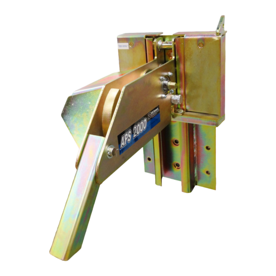
APS 2000
®
VEHICLE
RESTRAINT
Installation and Owner's Manual
This manual applies to Vehicle Restraints manufactured beginning
AUGUST 2013 with the serial numbers 15,017,001 and higher.
Do not install, operate or service this product
unless you have read and understand the
Safety Practices, Warnings, and Installation
and Operating Instructions contained in this
manual. Failure to do so could result in death
or serious injury.
©2017 4Front Engineered Solutions, Inc. - APS Resource
5609 RS 01/17
Advertisement
Table of Contents

Summary of Contents for APS 2000
- Page 1 Safety Practices, Warnings, and Installation and Operating Instructions contained in this manual. Failure to do so could result in death or serious injury. ©2017 4Front Engineered Solutions, Inc. - APS Resource 5609 RS 01/17...
-
Page 2: Table Of Contents
Notice is used to address practices not related to Indicates a potentially hazardous situation which, if personal injury. not avoided, could result in death or serious injury. ©2017 4Front Engineered Solutions, Inc. - APS Resource 5609 RS 01/17 PAGE 1... -
Page 3: Limited Warranty
® be as set forth in this Limited Warranty. This Limited Warranty will be null and void if the original purchaser does not notify APS Resource’s warranty department within ninety (90) days after the product deficiency is discovered. THERE ARE NO WARRANTIES, EXPRESS OR IMPLIED, WHICH EXTEND BEYOND THE DESCRIPTION ON THE FACE HEREOF, INCLUDING, BUT NOT LIMITED TO, A WARRANTY OF MERCHANTABILITY OR OF FITNESS FOR A PARTICULAR PURPOSE, ALL OF WHICH APS RESOURCE HEREBY DISCLAIMS. -
Page 4: Safety Practices
Be certain bystanders in the driveway stand clear when a lifting device. Lifting by hand may result in back injury. the Vehicle Restraint is operated. If you have any problems or questions, contact APS Re- Do not install the Vehicle Restraint anchor bolts into aged source at 262-518-1000. -
Page 5: Installation
Do not install the Vehicle Restraint anchor bolts into aged or unsound concrete. TOOLS REQUIRED 1. The dock face on which the APS 2000 Vehicle - Welder Restraint will be mounted must be flat and vertical - Impact or rotary drill with 5/8" diameter concrete drill bit to prevent binding of carriage assembly. - Page 6 3. Drill 5/8" dia holes into pit wall a minimum of 4-5/8" ALL 15 deep using holes in roller track as a guide. HOLES MUST BE ANCHORED ©2017 4Front Engineered Solutions, Inc. - APS Resource 5609 RS 01/17 PAGE 5...
- Page 7 7. If the APS 2000 vehicle restraint is being installed at TYPICAL ALONG SIDES a loading dock with a pit-style dockleveler that does &...
- Page 8 APS Resource INCH NONE PART DESCRIPTION Your Aftermarket Solution APS 2000 SUB-ASSEMBLY FIGURE 7 MOUNT CONTROL BOX ON LEFT SIDE OF DOOR OPENING. MOUNTING HARDWARE SUPPLIED BY OTHERS. ©2017 4Front Engineered Solutions, Inc. - APS Resource 5609 RS 01/17 PAGE 7...
- Page 9 *MOUNTING HARDWARE SUPPLIED BY OTHERS *DIMENSIONS ARE REFERENCE ONLY. USE OF A STANDOFF OR OTHER MOUNTING BRACKET COULD AFFECT THE DIMENSIONS SHOWN OR THE REQUIRED CABLE LENGTH. ©2017 4Front Engineered Solutions, Inc. - APS Resource 5609 RS 01/17 PAGE 8...
-
Page 10: Wiring Diagram
WIRING DIAGRAM ©2017 4Front Engineered Solutions, Inc. - APS Resource 5609 RS 01/17 PAGE 9... -
Page 11: Wire Harness Key
WIRE HARNESS KEY ©2017 4Front Engineered Solutions, Inc. - APS Resource 5609 RS 01/17 PAGE 10... -
Page 12: Operation
The notch on top of the hook must wrap over the RIG. See Figure 10. If vehicle cannot be hitched, red light will illuminate and the alarm will sound. ©2017 4Front Engineered Solutions, Inc. - APS Resource 5609 RS 01/17 PAGE 11... - Page 13 The APS 2000 control board has three optional features that can be selected by adjusting the DIP switch settings on the APS 2000 control board. See Figure 12 for the DIP switch setting location. For the DIP switch setting to take effect, the service tech- nician must disconnect power to the APS 2000 control panel prior to adjusting the DIP switch setting.
- Page 14 Reference Figure 14 for this DIP switch setting detail. • When DIP Switch #2 is in the OFF position, the hook will lower when the APS 2000 is switched to "RE- STRAINT OVERRIDE/HORN SILENCE". The APS FIGURE 14 2000 comes from the factory with this setting.
-
Page 15: Planned Maintenance
Without properly securing the carriage assembly, the Vehicle Restraint is unsafe to work on or around. Call an approved and qualified technician familiar with the APS Resource line of products. For a list of approved and qualified technicians call APS Resource at 1-262-518-1000. - Page 16 Push the buttons on the control box to be certain both lights are working. Replace LED modules as required. See the PARTS LIST for part numbers. ©2017 4Front Engineered Solutions, Inc. - APS Resource 5609 RS 01/17 PAGE 15...
- Page 17 MOTOR TOLERANCES ARE IN INCHES The information contained herein is proprietary and confidential to 4Front Engineered Solutions, Inc. - APS Resource and is to be UNLESS OTHERWISE SPECIFIED used solely for the express purpose of consideration and development of the article described herein and may not be reproduced or disseminated without the express written permission of 4Front Engineered Solutions, Inc.
- Page 18 - CRITICAL QUALITY DIMENSION herman.mckinney 11/19/2012 - REFERENCE DIMENSION SCALE JOB/REF NUMBER INCH PART DESCRIPTION PART NUMBER ISSUE MOVE ON GREEN CONTROL PANEL, APS2000 6013795 ONLY SIGN 709832 QTY. 1 ©2017 4Front Engineered Solutions, Inc. - APS Resource 5609 RS 01/17 PAGE 17...
-
Page 19: Troubleshooting
5. Hook and horn work but the lights do not change from red to green or green to red. Not wired properly. Check wiring. Limit switch LS2 not working. Replace. ©2017 4Front Engineered Solutions, Inc. - APS Resource 5609 RS 01/17 PAGE 18... -
Page 20: Parts List
Screw, 5/16-18 x 3/4 AP2548 Nut, U-Clip, 5/16-18 C51556 Bolt-On Lip Deflector AP5636 Washer, Flat, 1/2 000524 Bolt, Hex Head, 1/2-13 x 1.75 131370 Nut, Hex, 1/2-13 SE214241 ©2017 4Front Engineered Solutions, Inc. - APS Resource 5609 RS 01/17 PAGE 19... - Page 21 Motor Assy (Includes Items 16 & 17) AP2515 Pin, Cotter, 5/32 x 1-1/2 AP2509 Sprocket, Motor 713582 Slope Extension AP2550 Key, Drive Sprocket AP4164 Pin, Slope Extension C105495 Washer, Lock, 5/16 000501 ©2017 4Front Engineered Solutions, Inc. - APS Resource 5609 RS 01/17 PAGE 20...
- Page 22 Light Assy, LED, Grn AP2770 (Includes 2 Grn LRU's) Lens, Red SE823100 Lens, Green AP0027 LED Light Replacement Unit (LRU), Red 6006375 LED Light Replacement Unit (LRU), Grn 6006377 ©2017 4Front Engineered Solutions, Inc. - APS Resource 5609 RS 01/17 PAGE 21...
- Page 23 6007801 Circuit Board Retaining Clip AP4454 Washer, #8 AP4615 Screw, Pan Head AP4453 Wall Mounting Plate 6007802 Bolt, Hex Head AP4614 Sign, Move On Green Only 709832 ©2017 4Front Engineered Solutions, Inc. - APS Resource 5609 RS 01/17 PAGE 22...
- Page 24 Please direct questions to your local distributor or to 4Front Engineered Solutions, Inc. - APS Resource Your local APS Resource distributor is: ©2017 4Front Engineered Solutions, Inc. - APS Resource 5609 RS 01/17...
Need help?
Do you have a question about the 2000 and is the answer not in the manual?
Questions and answers