Table of Contents
Advertisement
Quick Links
Advertisement
Table of Contents

Related Manuals for MFJ MFJ-1224


Summary of Contents for MFJ MFJ-1224
- Page 1 MFJ RTTY/CW COMPUTER INTERFACE MODEL MFJ-1224 OWNER'S MANUAL...
-
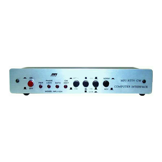
Page 2: Front Panel
Thank you for purchasing the MFJ-1224 Interface. The MFJ-1224 will allow you to transmit and receive RTTY and CW when used with your transceiver. During reception, the MFJ-1224 con- verts the CW or AFSK tones from your receiver into computer compatible TTL level signals. The computer then translates these signals into the represented alpha-numeric characters and displays them on the screen. -
Page 3: Back Panel
BACK PANEL The MFJ-1224 provides inputs and outputs to allow interfacing to nearly any possible com- bination of computer and transceiver. The back panel diagram below shows all the interface con- nections and the paragraphs below describe their uses. Only a few of the available connections will be used for any given application;... - Page 4 Next is a eight pin general purpose connector which allows you to adapt the interface to al- most any computer and software. An internal DIP switch allows the inputs and outputs to be in- verted if necessary to correspond to the requirements of your computer. From left to right, the pins are as follows: RTTY DEMOD This output is a TTL version of a received RTTY signal.
-
Page 5: Preliminary Connections
PRELIMINARY CONNECTIONS Input and output signals must be TTL level (+5 VDC and ground). Inputs are RTTY and CW KEY (RTTY and CW on general purpose connector). There is also a separate CW ID input for identi- fying in MORSE while operating RTTY. Outputs are DEMOD (RTTY DEMOD and CW DEMOD on the GENERAL PURPOSE CONNECTOR) and DIRECT and GRID BLOCK. -
Page 6: Internal Controls
If your radio teletype provides TTL voltages for input and output, you can hook it directly to the MFJ-1224. If not, you will have to use the loop supply circuit and a current loop to the TTL in- terfaces. (SEE November 1983, page 49.) - Page 7 Turn ON the RIT. Please do not touch the VFO. Transceivers without CW Filters: Adjust RIT for a higher pitch until the MFJ-1224's PHASE LOCK and DATA LEDs light. Finish the setting under the heading "FINISH". Transceivers with CW Filters, RIT and IF-SHIFT: Adjust RIT for a higher pitch.
- Page 8 Log the settings of the CONTROL(s) for future reference. Turn the X-TAL CAL OFF. With the controls of the MFJ-1224 set for CW, all Morse Tuning will be made with the VFO. Your transmit signal will appear on the frequency to which the other station is listening. If the transceiver has a digital display frequency counter, then your actual transmit frequency will be dis- played DURING TRANSMIT.
- Page 9 DATA LED is blinking on and off the most pronounced. 1. Set the switches on the MFJ-1224 for RTTY, 170 Hz shift, and NORMAL (SEE Fig. 3A). 2. Set the computer for 60 WPM RTTY. Most RTTY on the Amateur HF bands is set at 60 WPM, 170 Hz shift.
- Page 10 Computer Interface. CALIBRATION OF THE PLL FREQUENCY 1. Set the MFJ-1224 Computer Interface to receive ASCII at 300 baud, 170 Hz shift. 2. Record from AFSK Connector of the GENERAL PURPOSE CONNECTOR, two minutes of "*" and "U" (Capital U) repeatedly on a tape recorder. NOTE: The audio tone control should be set high.
-
Page 11: Software Considerations
4. If the counter doesn't read 2295 Hz, then adjust VR3 (see Fig 4) for a reading of 2295 Hz (±2 Hz). Calibration of the 850 Hz Shift 1. Set the MFJ-1224 front panel switches for 850 Hz shift. 2. Connect a frequency counter as in Calibration of the MARK Frequencies. 3. The frequency counter should read 2975 Hz. - Page 12 The MFJ-1223 is used to connect the MFJ-1224 to RS-232 Ports. Since the MFJ-1224 uses TTL voltage (+5 VDC) and RS-232 ports are ±12 VDC, a interface becomes necessary to intercon- nect. Our MFJ-1223 allows the use of the port.
- Page 13 II. C-64™ A. Using the MFJ-1265 or MFJ-1253 Software. NOTE: The connector cable supplied with the software has the proper connections for the GENERAL CONNECTION PORT and the C-64 USERS PORT. The DIP Switches are set at the factory for this computer, software, and cable.
- Page 14 III. APPLE™ A. Using the C. H. GALFO Software. NOTE: The DIP Switches must be set for this software as follows: MFJ-1224 General Connector Apple Game Port MFJ-1224 DIP Switches RTTY DEMOD CW DEMOD CW ID NOT USED RTTY PTT (IN)
- Page 15 NOT USED NOTES: 1. A TTL TO RS-232 CONVERTER MUST BE USED WITH THE CLAY ABRAMS SOFTWARE. (We recommend the MFJ-1223). 2. PLACE A 1 µF ELECTROLYTIC CAPACITOR FROM PIN 2 (DATA IN) OF THE SERIAL I/O TO GROUND. Hamsoft™ and Hamtext™ are trademarks of Kantronics, Inc.
- Page 16 Figure 4 Page 15...
- Page 17 Page 16...
Need help?
Do you have a question about the MFJ-1224 and is the answer not in the manual?
Questions and answers