Table of Contents
Advertisement
5009272
For replacement parts visit
WENPRODUCTS.COM
Your new tool has been engineered and manufactured to WEN's highest standards for dependability,
ease of operation, and operator safety. When properly cared for, this product will supply you years
of rugged, trouble-free performance. Pay close attention to the rules for safe operation, warnings,
and cautions. If you use your tool properly and for intended purpose, you will enjoy years of safe,
reliable service.
NOTICE: Please refer to wenproducts.com for the most up-to-date instruction manual.
VARIABLE SPEED
ELECTRIC ROUTER
IMPORTANT:
NEED HELP? CONTACT US!
Have product questions? Need technical support?
Please feel free to contact us at:
800-232-1195
techsupport@wenproducts.com
WENPRODUCTS.COM
Model # 6033
bit.ly/WENvideo
(M-F 8AM-5PM CST)
Advertisement
Table of Contents

Subscribe to Our Youtube Channel
Summary of Contents for Wen 6033
- Page 1 WENPRODUCTS.COM IMPORTANT: Your new tool has been engineered and manufactured to WEN’s highest standards for dependability, ease of operation, and operator safety. When properly cared for, this product will supply you years of rugged, trouble-free performance. Pay close attention to the rules for safe operation, warnings, and cautions.
-
Page 2: Table Of Contents
Know Your Electric Router Assembly and Adjustment Operation Maintenance Troubleshooting Guide Exploded View and Parts List Warranty Statement TECHNICAL DATA Model Number: 6033 Motor: 120V, 60Hz, 15A, 2.5HP Variable Speed: 8,000 - 23,000 RPM Collet Size: 1/2", 1/4" Net Weight: 18 lbs Assembled Dimension: 12.5 x 6.2 x 12.7 in. -
Page 3: General Safety Rules
GENERAL SAFETY RULES Safety is a combination of common sense, staying alert and knowing how your item works. SAVE THESE SAFETY INSTRUCTIONS. WARNING! Read all safety warnings and all instructions. Failure to follow the warnings and instruc- tions may result in electric shock, fire and serious injury. To avoid mistakes and serious injury, do not plug in your tool until the following steps have been read and understood. - Page 4 GENERAL SAFETY RULES POWER TOOL OPERATION 1. Avoid accidental start-ups. Make sure the power switch is in the OFF position before connecting the plug to a power source or carrying the tool. 2. Check power tool for damaged parts. Check for misalignment of moving parts, jamming, breakage, improper mounting, or any other conditions that may affect the tool’s operation.
-
Page 5: Electrical Information
ELECTRICAL INFORMATION DOUBLE INSULATION Double insulation is a concept in safety in electric power tools, which eliminates the need for the usual three-wire grounded power cord. All exposed metal parts are isolated from the internal metal motor components with protecting insulation. Double insulated tools do not need to be grounded. WARNING: The double insulated system is intended to protect the user from electric shock resulting from a break in the tool’s internal insulation. -
Page 6: Specific Rules For Electric Router
SPECIFIC RULES FOR ELECTRIC ROUTER 1. The speed range of the router is 8,000 - 23,000 RPM. Make sure that the router bit you wish to use is suitable for your router. Check the router bit’s maximum speed rating specified by the manufacturer. It must be capable of operating at the maximum rotation speed of 23,000 RPM. -
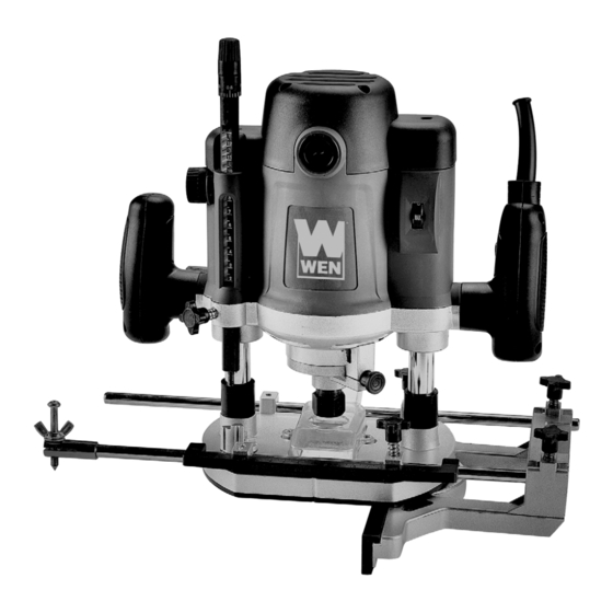
Page 7: Know Your Electric Router
KNOW YOUR ELECTRIC ROUTER Use the diagram below to become familiarized with all the controls and accessories of your electric router. Refer to the next page for explanations of each control. Make sure to account for all the parts and accessories. If any part is damaged or missing, please contact our Customer Service at (800) 232-1195, M-F 8-5 CST. - Page 8 KNOW YOUR ELECTRIC ROUTER WARNING: Do not attempt to plug in or operate your router until the entire operator’s manual has been read and understood. Failure to do so could result in personal injury and damage to the tool. 1. FINE-TUNE ADJUSTMENT DIAL The fine-tune adjustment dial (Fig.
-
Page 9: Assembly And Adjustment
KNOW YOUR ELECTRIC ROUTER 8. POWER CONTROL Press down the trigger to start the router. Always ensure you are holding the router properly before starting the tool. Your router is built with a lock-on button (Fig. 5). To lock the switch ON, press the trigger all the way down and then press down the lock-on button. - Page 10 ASSEMBLY AND ADJUSTMENT INSTALLING & REMOVING ROUTER BITS WARNING: Router bits are extremely sharp. Take care when handling bits as they can cause serious injury. What you need: • Wrench • Router Bit (not included) • 1/4" Shank Adaptor (Optional) Make sure that the router bit you wish to use is suitable for your router.
- Page 11 ASSEMBLY AND ADJUSTMENT SETTING THE CUTTING DEPTH The cutting depth of the router is indicated by the distance between the bottom of the depth stop pole and the depth set turret. 1. Install the desired router bit as described in page 10. 2.
- Page 12 ASSEMBLY AND ADJUSTMENT SETTING THE ROUTER SPEED The router is equipped with a variable speed dial (Fig. 13) that can control the bit rotation speed from 8,000 - 23,000 RPM. If the router speed is too high, friction will generate excessive heat and scorch the workpiece. If the router speed is too low, the bit will tear the material and result in rough or uneven cuts.
-
Page 13: Operation
ASSEMBLY AND ADJUSTMENT DIRECTION OF FEED If you are looking down from the top of the router, the bit will revolve in a clockwise direction. This gives the router a tendency to twist coun- terclockwise in your hands, particularly when starting the tool. For maximum safety and control, feed the router in a counterclockwise direction when routing the exterior edges of your workpiece. - Page 14 OPERATION CUTTING ALONG A STRAIGHT EDGE What you need: • Straight Guide Fence • Two Fence Poles • Fence Pole Scale (optional) • Workpiece with a straight edge The straight guide fence is used to create straight cuts along a workpiece with a straight edge that can be followed.
- Page 15 (6033TGA) with a center hole diameter of 1-3/16" from wenproducts.com, to fit other template guides and bushings. 1. Remove the four M5 X 10 screws (Part No. 6033-076) holding the plastic base plate, and remove the base plate.
-
Page 16: Maintenance
MAINTENANCE WARNING: To avoid accidents, always disconnect the tool from the power supply before cleaning or performing any maintenance. CLEANING 1. Regularly clean the router with a soft cloth or compressed air. Remember to wear safety goggles when cleaning tools with compressed air. 2. -
Page 17: Troubleshooting Guide
1195, M-F 8-5 CST for a replacement car- 007) falls out eration affected the thread tolerance. bon brush cap ( 6033-007) that will resolve this issue. 1. Unlock the plunge lock lever by moving 1. The plunge lock lever is locked. - Page 18 EXPLODED VIEW AND PARTS LIST EXPLODED DIAGRAM & PART LIST...
-
Page 19: Exploded View And Parts List
EXPLODED VIEW AND PARTS LIST Part No. Description Qty. Part No. Number Qty. 6033-001 Depth Adjusting Dial 6033-041 Bolt M6 X 20mm 6033-002 Fine Adjustment Rod 6033-042 1/2" Collet & Nut Assembly 6033-003 Fine Adjustment Dial 6033-043 Position Rod 6033-004... - Page 20 LIMITED TWO YEAR WARRANTY WEN Products is committed to building tools that are dependable for years. Our warranties are consistent with this commitment and our dedication to quality. LIMITED WARRANTY OF WEN CONSUMER POWER TOOLS PRODUCTS FOR HOME USE GREAT LAKES TECHNOLOGIES, LLC (“Seller”) warrants to the original purchaser only, that all WEN con- sumer power tools will be free from defects in material or workmanship for a period of two (2) years from date of purchase.
Need help?
Do you have a question about the 6033 and is the answer not in the manual?
Questions and answers