
Summary of Contents for ORMELABS MW1008P
- Page 1 LCR meter MW1008P User Manual Copyright Ormelabs © 2010-2015 http://www.ormelabs.com MW1008P, user manual...
-
Page 2: Table Of Contents
Precision Precision of resistances/impedances Precision of inductances Precision of capacitors Theory of operation Signal generator Phase detector and analog/digital converter Transformers Calibration Parameterizing the calibration Calibration Error messages Diagnostics Keyboard test Buzzer test i/v complex A/D results MW1008P, user manual... -
Page 3: General Information
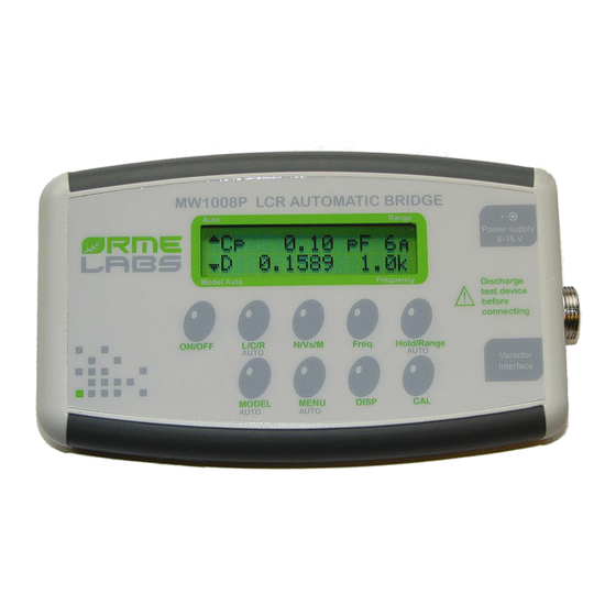
The MW1008P LCR Meter is a multi-frequency impedance measuring instrument capable of measuring resistance, capacitance, inductance or transformer parameters from 1 mΩ to 100 MΩ. The MW1008P LCR meter has a basic accuracy of 0.2% and has 11 test frequencies plus one user definable. -
Page 4: Terms And Symbols
Admittance, 1/Z Siemens, S ohm, Impedance module Z Rs or ESR Serial resistance, ohm, Real part of impedance Reactance, ohm, imaginary part of impedance Conductance, siemens, S Real part of admittance (Y) Susceptance, siemens, S MW1008P, user manual... -
Page 5: Glossary
Impedance ranges that the instrument uses to perform measurements. Impedance : Complex value characterizing a passive component. The impedance has a real component (résistance) in series with an imaginary component (reactance). A pure resistance doesn’t have reactance while pure coils and capacitors doesn’t have resistance. MW1008P, user manual... - Page 6 This is the rms value delivered from the instrument with no load for creating a current through the device under test. The source resistor as well as the actual DUT impedance imply that actual voltage across the DUT is always below this value. MW1008P, user manual...
-
Page 7: Generalities
GENERALITIES This chapter gives an overview of the MW1008P characteristics. For further information please refer to the operation section. DISPLAY The two lines of the LCD show measured values, selected parameters, instrument status and various messages. When making normal measurements,... -
Page 8: Keypad
Auto Range mode. In Manual or Hold ranging mode, this letter becomes a blinking “H” character. Pressing this key for two seconds or longer returns to the Auto mode. See also chapter “Impedance ranges” page 24 for more details about impedance ranges. MW1008P, user manual... - Page 9 Pressing the ‘Change’ key will step the value of the selected digit. When the desired value has been entered, pressing the key will record this value. Pressing the key under the right arrow will allow the user to set the MW1008P, user manual...
- Page 10 Sorting mode is disabled, pressing DISP. cycles through the following display types: The value being measured The deviation of the value from the current value – The D symbol next to the measured parameter indicates that this function is active. MW1008P, user manual...
- Page 11 LCR meter for the currently selected test frequency. Pressing the key for more than two seconds displays the zeroing options – OPEN SHORT Exit (note that the options are in all capital letters). This option performs an open/short calibration through the entire range of test frequencies. MW1008P, user manual...
-
Page 12: Passive Components
COG/NPO capacitors, which can exhibit only a 0.003%/°C variation. Inductors, especially those with non-air cores, may vary largely with temperature. Ambient and DUT temperature drifts introduce error into measurement. Control ambient temperature changes to reduce errors. MW1008P, user manual... - Page 13 During normal operation, the AC current source swings negative 50% of the time, which results in an inverse polarization of the capacitor under test. To prevent this inverse polarization, a DC bias can be applied to prevent the voltage across the part from MW1008P, user manual...
- Page 14 (100 Ω for ranges 1 and 2). A value of 470 µF/63V will be sufficient in most cases. The value of resistor R2 will be of 390 Ω. A short zeroing should be performed replacing the capacitor by a MW1008P, user manual...
- Page 15 For low value inductors, the reactance becomes relatively low, so the series resistance is more significant and the series model is the appropriate choice. For very small inductance values a higher measurement frequency will yield better accuracy. MW1008P, user manual...
- Page 16 L mode will give the value of the inductor. Inductors biasing For measurement in range 1 or 2 one will take the following values : R2 = R3 = 390 Ω/1W C1 = C4 = 470 µF/160V MW1008P, user manual...
- Page 17 The measurement is done with no current. It is possible to connect shortly a parallel resistor in order to drain some current. It is only necessary then to do a little calculation to find the actual internal resistance. MW1008P, user manual...
-
Page 18: Displayed Parameters
Pressing more than 2s the L/C/R key switches the instrument in automatic mode. The instrument determines the function the most appropriate function according to some criterias resumed in the graphic below. When impedance is below 10 m the resistance function is selected. MW1008P, user manual... - Page 19 MEASUREMENTS ON TRANSFORMERS The MW1008P has a special function for measuring a transformer ratio between primary and secondary windings, calculation of the equivalent secondary voltage for a supply transformer and for measuring mutual inductance between primary and secondary windings. The use of this function needs use of the 4 wires mini-pincers cable MW10. To use this mode...
- Page 20 When 2 winding are close to each other, the flux created by one can establish in the second. The mutual inductance coefficient is the ratio of the flux produced by coil 1 in coil 2 to the current that flows through coil 1. MW1008P, user manual...
- Page 21 SORTING COMPONENTS The MW1008P allows comparison of components parameters to a pre-defined value. The instrument will calculate the difference to the pre-programmed value, which could be displayed in absolute difference or percentage formats. To access sorting function, press key Menu. For the other...
- Page 22 The difference in percentage to the current value. The symbol and unit in % indicates that this function is activated. MW1008P, user manual...
-
Page 23: Test Conditions
Modification of coefficients N1 and N2 : L/C/R Increments N1 of 10 units Increments N1 of one unit n/Vs/ Decrements N1 of 10 units MODEL Decrements N1 of one unit MENU Multiply N2 by 2 Frequ. Divide N2 by 2 DISP. MW1008P, user manual... -
Page 24: Impedances Ranges
IMPEDANCE RANGES The MW1008P has 6 ranges of impedance Resi- Inductance Capaci- (R1-R6). The impedance range can be Range stance tance source selected manually or the instrument can be 0.01 µH - 99.9 mF- 1mΩ- 100 Ω configured in auto range mode, which is the 2.4/f... -
Page 25: Open-Short Calibration
The values of Gpp and Cpp being measured during an open circuit measurement. The MW1008P takes these elements into account by applying the correction given on the schematics (a) above. The calibration should be done at each time one proceed to... - Page 26 Case of measurements on transformers The OPEN/SHORT calibration must not be used. MW1008P, user manual...
-
Page 27: Connecting To A Passive Component
CONNECTING TO A PASSIVE COMPONENT The MW1008P uses a Kelvin type The impedance is measured connection with 4 wires to measure the between those two points component. This allows the instrument to let a current pass through the component using wires LD (Low Drive) and HD... - Page 28 For a classical use, you just need to use a standard 5 pins male DIN plug. The cables should be shielded type, the shields being connected to ground (pin 3) HS (High Sense) HD (High Drive) 0V (GND) LD (Low Drive) LS (Low Sense) MW1008P, user manual...
-
Page 29: Precision
= 1 mΩ / 1 kΩ = 10 = 1 kΩ / 1GΩ = 10 Precision of the resistance = ±(0,2 + 0,0002)% ≈ ± 0,2% Precision of Q : ∆Q = (0,2/100) ×(1+0,0005 ) = 0,002 MW1008P, user manual... -
Page 30: Precision Of Inductances
= (Cm × f ) / 160 mF f : Test frequency in kHz Precision of Q = (A / 100) (1+Q With A precision of capacitor calculated as above Note : The precision of Q is an absolute value and not a percentage MW1008P, user manual... - Page 31 Base precision MW1008P, user manual...
-
Page 32: Signal Generator
Figure X shows the block diagram of MW1008P and shows how the instrument measures unknown impedances. A sinusoidal signal is applied to the unknown impedance ZX through a source resistance R , which changes according to the impedance range. - Page 33 20 ms or 16.67 ms depending on whether one is dealing with an mains of 50 Hz or 60 Hz. The resulting value is obtained by measuring the discharge of the integrating capacitor with a meter. MW1008P, user manual...
-
Page 34: Transformers
In mutual inductance measurement mode, the instrument measures the primary current and secondary voltage to determine an impedance Z then the mutual inductance is / ω calculated by M = Z MW1008P, user manual... -
Page 35: Calibration
CALIBRATION The MW1008P can be calibrated using a standard kit of six reference resistors (10 Ω, 100 Ω, 1 k, 10 k, 100 kΩ and 1 MΩ) or an external calibrator. The value of each resistor is marked on the packaging of these resistors. - Page 36 The instrument will now carry out the calibration of impedance for each of the ranges and at all frequencies. There are six steps STP3 to STP8 where you should connect the calibrating resistors supplied with the kit and whose values have been previously programmed MW1008P, user manual...
-
Page 37: Error Messages
X takes values from 1 to 6 depending on the relevant range Y takes the values A to J according to the frequency of interest (A = 100 Hz, J = 15.625 kHz) Checksum Error Consult Ormelabs maintenance. MW1008P, user manual... -
Page 38: Diagnostics
(0 to 1023) and the position of the key. The output of the keyboard test mode occurs when all keys have been tested. First screen when you enter the test mode of the keyboard. MW1008P, user manual... - Page 39 Each of these two vectors has a component in phase (real) and a quadrature component (imaginary). The absolute coordinates of these two vectors are relative to the reference resistance of the current range. To give a physical meaning to these MW1008P, user manual...
-
Page 40: A/D Results
0 ° to 270 ° by 90 ° due to the key n/Vs/M. Press the L/C/R key to select the voltage measurement, then press n/Vs/M to select an angle of 0 °. Note that this angle is an angle MW1008P, user manual... - Page 41 Vi = 0.79745 - 0.23967 = 0.55778 You can do the same thing with the current by pressing the L/C/R key. The values shown are normalized values directly taken from the converter from 0 to 1. MW1008P, user manual...
- Page 42 ORMELABS 87, Avenue Victor Hugo 94100 St Maur des Fossés , FRANCE Web : www.ormelabs.com Email : infos@ormelabs.com Tel: +33 (0) 1 82 52 27 11 MW1008P, user manual...
Need help?
Do you have a question about the MW1008P and is the answer not in the manual?
Questions and answers