Table of Contents
Advertisement
Quick Links
Advertisement
Table of Contents
Troubleshooting

Subscribe to Our Youtube Channel
Summary of Contents for Hach Ultra MET ONE 237AB
- Page 1 701076 MET ONE 237AB Particle Detector USER MANUAL June 2008, Edition 5...
- Page 2 701076 MET ONE 237AB Particle Detector USER MANUAL June 2008, Edition 5 © Hach Ultra Analytics, Inc., 2008. All rights reserved. Printed in the U.S.A.
-
Page 4: Table Of Contents
Table of Contents Section 1 Specifications ........................3 Section 2 General Information ......................5 2.1 Safety information ........................5 2.1.1 Use of hazard information....................5 2.1.2 Precautionary labels ......................5 2.1.3 Laser safety information...................... 6 2.1.4 Electrostatic discharge (ESD) considerations ..............6 2.1.5 Battery safety information .................... - Page 5 Table of Contents Section 11 Certification ........................39 Appendix A Optional Accessories ....................41 A.1 Relative humidity/Temperature (RH/T) probe ................41 A.2 High-pressure diffuser........................41 A.3 RS485 converter ........................41 A.4 External printer...........................42 A.5 PortAll software..........................42 A.6 Carrying case..........................42 Appendix B Computer Interface Operations ................43 B.1 Data analysis for ISO 14644 ......................43 B.1.1 Computer communications ....................43 Appendix C PortAll Software...
-
Page 6: Section 1 Specifications
Section 1 Specifications Specifications are subject to change without notice. General Size 170.94 mm x 58.42 mm x 165.10 mm (6.7" W x 4.5" H x 11.7" D) Weight 3.0 kg (6.8 lb) Maximum count displayed 9,999,999 Sample flow rate 0.1 cfm Number of size ranges 2, 4, 5, 6 (specified at the time of order) - Page 7 Specifications...
-
Page 8: Section 2 General Information
Section 2 General Information 2.1 Safety information Read this entire manual before unpacking, setting up or operating this equipment. Pay attention to all danger and caution statements. Failure to do so could result in serious injury to the operator or damage to the equipment. To make sure that the protection provided by this equipment is not impaired, do not use or install this equipment in any manner other than that specified in this manual. -
Page 9: Laser Safety Information
General Information 2.1.3 Laser safety information This particle counter contains a laser-based sensor that is a Class 1 product (as defined by 21 CFR, Subchapter J, of the Health and Safety Act of 1968) when used under normal operation and maintenance. The manual contains no procedures for service of internal parts within this unit. -
Page 10: General Product Information
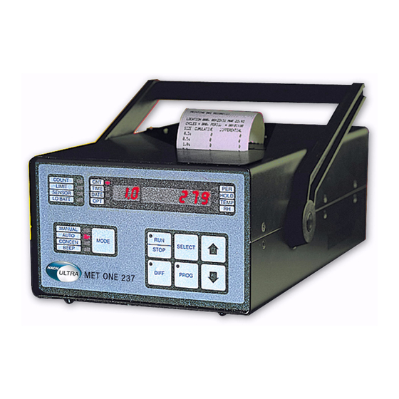
General Information 2.2 General product information The MET ONE 237 particle counter is a battery operated, laser based particle counter that is used in a walk-around sampling routine. The counter can store up to 500 records for each sample with a different location label on the record. The data records may later be printed or downloaded to a computer for analysis. -
Page 11: Theory Of Operation
General Information 2.3 Theory of operation The MET ONE 237A/B particle counter is a compact, fully featured particle counter that includes sensor, pump, electronics and the printer. Both the variants use the same sensor, pump, CPU and display electronics. The MET ONE 237A particle counter is calibrated with channel one sensitivity of 0.5 µm and the MET ONE 237B particle counter is calibrated with a channel one sensitivity of 0.3 µm. -
Page 12: Section 3 Installation
Section 3 Installation DANGER Only qualified personnel should conduct the tasks described in this section of the manual. This section describes the setup of the MET ONE 237 particle counter and connections to the equipment. If necessary, contact the Technical Support Department with questions regarding the compatibility or suitability of this product for a specific application. -
Page 13: Mechanical Installation
Installation 3.2 Mechanical installation The MET ONE 237 particle counter is ready to use when unpacked. Check for all the connections to the equipement. 3.2.1 Install the isokinetic probe The isokinetic sample probes are used for accurate air sampling in particle counting applications. -
Page 14: Install The Purge Filter
Installation 3.2.2 Install the purge filter The purge filter (refer to Figure 3 on page 9, item 3) is used for maintenance (purge and zero count) of the MET ONE 237 particle counter. The purge filter permits direct sampling of pressurized air at pressures ranging from 30 to 150 psi. Note: It is recommended that the purge filter be applied to the counter before moving the MET ONE 237 particle counter to avoid cross contamination. -
Page 15: Connect The Ac Adapter
Installation 3.2.4 Connect the AC adapter The AC adapter (refer to Figure 3 on page 9, item 6) is used to charge the internal battery and use the MET ONE 237 particle counter with a standard 115 VAC outlet. To connect the AC adapter: 1. -
Page 16: Section 4 System Start Up
Section 4 System Start Up 4.1 Power up Turn on the switch at the back of the MET ONE 237 particle counter (refer to Figure 6 on page 12). The counter will display the main screen when turned on (Figure 7 on page 15). - Page 17 System Start Up...
-
Page 18: Section 5 Operation
Section 5 Operation The MET ONE 237 particle counter must be configured before operation for parameters such as sample time and count alarm thresholds. 5.1 Front panel overview The front panel of MET ONE 237 (refer to Figure 7) particle counter consists of: •... -
Page 19: Setup
Operation Table 1 Indicators and key features or functions (continued) Name Description DIFF Helps to operate the different settings of the counter. Helps to select the different settings of the counter. This is used to set the date and time, SELECT enable the printer, change the sample period, set the alarm limits, set the number of sampling cycles and so on. - Page 20 Operation Table 2 Default parameter settings (continued) Parameter Setting Baud rate 9600 Sample time 1 minute (length of sample period) Hold time 1 second (hold time between samples in Automatic mode) Program mode Unlocked (allows user programming). In the Manual counting mode, the counter will take one sample of the programmed length (default is 6-seconds) and stop.
- Page 21 Operation 5.3.1.3 Enable the printer To enable the printer in the manual mode: 1. Press and hold the key until the light is lit. SELECT 2. Press the arrow key until the 3-digit display shows Prn and the 7-digit DOWN display shows the status of the printer.
-
Page 22: Automatic Mode
Operation 5.3.2 Automatic mode In the automatic mode, the MET ONE 237 particle counter automatically takes a specified number of samples and stops, allowing unattended operation. The automatic mode covers the typical programming requirements for the common functions associated with the MET ONE 237 particle counter. - Page 23 Operation 5.3.2.3 Set the sample period and hold time Note: Set the HOLD time to a minimum of 10 seconds when the printer is enabled. A sample record will be overlooked when calculating the average counts, because of printer operation during the calculations.
-
Page 24: Concentration Mode
Operation To sample the room in the automatic mode: 1. Carry the MET ONE 237 particle counter to the center of the first area of the large room to be tested. 2. Place or hold the counter about 4 feet off the floor. 3. - Page 25 Operation Figure 9 Calculation using 3-second period 3-second period Recalculation and display update Seconds Figure 10 Calculation using 10-second period 10-second period Recalculation and display update Seconds To program the MET ONE 237 particle counter for Concentration mode: 1. Press and hold the key until CONCEN is lit.
-
Page 26: Beep Mode
Operation 2. Press and hold the key. The light on the key turns red and all the digits PROG PROG begin to flash. 3. Press the arrow keys to change the digits to the required value. DOWN Note: The period will not accept settings exceeding 10 seconds. 4. -
Page 27: Environmental Alarms
Operation To program the settings for relative humidity/temperature: 1. To change the alarm limits, press and hold the key until the TEMP light is lit. SELECT The 7-digit display will show the temperature reading and the scale being used. 2. Press and hold the key. -
Page 28: Section 6 Maintenance
Section 6 Maintenance DANGER Only qualified personnel should conduct the tasks described in this section of the manual. DANGER Electrocution hazard. Always disconnect the power to the instrument before making any electrical connections. WARNING Harmful radiation exposure. Do not use the controls or adjustments or performance of procedures other than those specified. -
Page 29: Battery Replacement
Maintenance Figure 11 Position of screws on the top cover of the counter Position of three screws on one side (Screws that hold top cover) 6.2.1 Battery replacement WARNING An explosion can occur if the internal battery is replaced incorrectly. To replace the rechargeable battery pack: 1. -
Page 30: Replace The Printer Ribbon
Maintenance 6.3.3 Replace the printer ribbon To replace the printer ribbon: 1. Remove the two screws that hold the printer bar and remove the printer bar. 2. Remove the four ¼” nuts that hold the print head assembly. 3. Tilt the chassis tray up as in section 6.3 on page 26, step 1. - Page 31 Maintenance...
-
Page 32: Section 7 Troubleshooting Procedures
Section 7 Troubleshooting Procedures 7.1 Common problems Table 3 Trouble shooting procedures Message displayed on the LCD Description User action Turn off the counter and attach the AC adapter/charger to Indicates that the the power input jack at the bottom of the counter. LO BATT battery requires Place the counter on the stand or on any stable surface and... -
Page 33: Pump Troubleshooting
Troubleshooting Procedures 7.3 Pump troubleshooting If the vacuum pump does not operate, or exhibits any questionable symptoms such as unusual sound or vibration, it may be removed for maintenance to restore it to optimum operation. 7.3.1 Disassembly and cleaning of the pump Prerequisites: •... - Page 34 Troubleshooting Procedures Figure 13 Removal of the bracket Bracket Figure 14 Removal of top of the pump Locator pin Top of the pump Figure 15 Removal of the pump body Pump body...
-
Page 35: Pump Optimization
Troubleshooting Procedures Figure 16 Removal of carbon vanes Carbon vane 7.3.2 Pump optimization To optimize the pump: 1. Assemble the pump again. Loosen the setscrew plug in top bracket and make the electrical connection to the MET ONE 237 particle counter. 2. -
Page 36: Accessories
Section 8 Replacement Parts and Accessories 8.1 Accessories Description Quantity Catalog Number Isokinetic probe—Wand style 203015–3 Isokinetic probe—Direct mount 2080613 Purge filter 2080442 770007 (115 VAC) AC adapter 770012 (230 VAC) 770009 (100 VAC) Thermal printer paper (optional) 460519 RH/Temp probe (optional) 2080825–1 High-pressure diffuser (optional) 2080372–6... - Page 37 Replacement Parts and Accessories...
-
Page 39: Section 10 Limited Warranty
Section 10 Limited Warranty Hach Ultra warrants this instrument to be free of defects in materials and workmanship for a period of one year from the shipping date. If any instrument covered under this warranty proves defective during this period, Hach Ultra will, at its option either repair the defective part without charge for extra parts and labor or provide an equivalent replacement in exchange for the defective product. -
Page 41: Section 11 Certification
Section 11 Certification This section contains copies of certification documents and a statement of conformity to WEEE requirements. DECLARATION of CONFORMITY Pacific Scientific Instruments 481 California Avenue Grants Pass, Oregon 97526 declare under sole responsibility that the Particle Counter, Model 227, part number 2082611 conforms to Directive 89/336/EEC for Electromagnetic Compatibility and Directive 73/23/EEC for Low Voltage. - Page 42 Certification Warranty Pacific Scientific Instruments (“Seller”) warrants that the Products will operate substantially in conformance with Seller’s published specifications, when subjected to normal, proper and intended usage by properly trained personnel, for a period of one (1) year from the date of shipment to Buyer (the “Warranty Period”). Seller agrees during the Warranty, provided it is promptly notified in writing upon the discovery of any defect and further provided that all cost of returning the defective Products to Seller are prepaid by Buyer, to repair or replace, at Seller’s option,...
-
Page 43: Appendix A Optional Accessories
Appendix A Optional Accessories A.1 Relative humidity/Temperature (RH/T) probe The RH/T probe (refer to Figure 4 on page 10) monitors relative humidity (10% to 90%) and temperature (5 to 125 °F or –15 to 50 °C). The MET ONE 237 particle counter displays the reading and includes it in the internal particle count data record. -
Page 44: External Printer
A.4 External printer An external printer option provides the printout of the count and temperature/relative humidity data. Refer to Appendix D on page 49 for additonal information. A.5 PortAll software The PortAll software (refer to Figure 21) is used to transfer count data from the buffer of the buffer and to display the data on the computer in a spreadsheet format. -
Page 45: Appendix B Computer Interface Operations
Appendix B Computer Interface Operations B.1 Data analysis for ISO 14644 The primary reason for a computer interface with the MET ONE 237 particle counter is to download the count data for analysis. ISO 14644 is the governing standard for clean-rooms. The MET ONE 237 particle counter cannot perform the calculations internally. - Page 46 B.1.1.1 Communication protocol The counter has the following fixed parity and protocol: • Eight (8) data bits • One (1) stop bit • No parity Table 4 describes the ASCII commands that are supported by the MET ONE 237 particle counter.
- Page 47 B.1.1.2 Data record format Each counter can send a record of the data available. The data record is a string of ASCII characters where the position in the string identifies the meaning of the character. The length of the string changes with the amount of data points available from the counter. Each data point is preceded by a 3-character tag that identifies the type of data that follows in the next six data characters.
-
Page 49: Appendix C Portall Software
Appendix C PortAll Software The clean-room classification standards FS 209E and ISO 14644–1 require specific particle count measurements and calculations to verify the cleanliness level of a clean-room or clean area. The PortAll software automatically generates clean-room verification results from the measurement data from the MET ONE 237 particle counter. C.1 Connections In order to communicate with a computer, the MET ONE 237 RS232 mode found in the SIO menu is set to normal (printer disabled). - Page 50 • The total count data returned from the particle counter must be normalized to counts per unit volume to obtain a correct classification. The PortAll software will automatically normalize (counts x 10) the count data, but this feature must be setup (refer to the online User's Guide for instructions).
-
Page 51: Appendix D Dpu-414 Printer
Appendix D DPU–414 Printer The clean-room classification standards FS 209E and ISO 14644–1 require specific particle count measurements and calculations to verify the cleanliness level of a clean-room or clean area. D.1 Printer setup The MET ONE 237 particle counter may be purchased without an internal printer and the Model DPU-414 printer is available as an optional accessory. -
Page 52: Counter Setup For The Printer
7. Press the button to set the second switch position to ON. The printer will print ONLINE “2 (ON): Printing speed = High” and open the next switch position for programming. 8. Continue programming the remaining positions using the button to set ON ONLINE conditions and the button to set OFF conditions. - Page 53 Index ASCII commands ............. 44 Maintenance guidelines ........... 25 Automatic mode ............19 Manual mode ............16 Mode Key ..............15 Battery replacement ..........26 Battery safety information .......... 6 operation, principle ............. 8 Beep ................ 23 bracket ..............30 PortAll software ............
- Page 54 Index...
- Page 55 Electrical equipment marked with this symbol may not be disposed of in European public disposal systems after 12 August of 2005. In conformity with European local and national regulations (EU Directive 2002/96/EC), European electrical equipment users must now return old or end-of life equipment to the Producer for disposal at no charge to the user.
- Page 56 Trademarks are property of their respective owners. Specifications subject to change without notice.
- Page 57 Thank you for reading this data sheet. For pricing or for further information, please contact us at our UK Office, using the details below. UK Office Keison Products, P.O. Box 2124, Chelmsford, Essex, CM1 3UP, England. Tel: +44 (0)330 088 0560 Fax: +44 (0)1245 808399 Email: sales@keison.co.uk...
Need help?
Do you have a question about the MET ONE 237AB and is the answer not in the manual?
Questions and answers