Table of Contents
Advertisement
Quick Links
Advertisement
Table of Contents

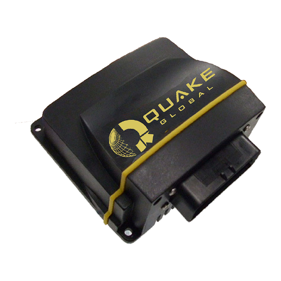
Summary of Contents for Quake Global QPRO
- Page 1 QPRO Technical Data Sheet 1137-0901 Revision A Document Number 1137-0901 Rev: A...
- Page 2 QPRO Technical Data Sheet Revision History ECO# REASON DATE Rev. A 00261 Initial Production Release Representante autorizado no Brasil: Hidromec Indústria e Comércio Ltda Rua Sacadura Cabral - 351 Rio de Janeiro RJ Fone: + 55 21 3622 8000 info@hidromechc.com.br...
-
Page 3: Table Of Contents
) .................. 17 USTOMER NTERFACE NTERNAL 4.7.1 Memory ..........................17 4.7.2 Real-Time Clock (RTC) ......................17 ................. 17 NVIRONMENTAL ONSIDERATIONS QPRO Data Interface Specifications ................19 ......................19 NTERFACES & C ............19 NVIRONMENTAL PECIFICATIONS ERTIFICATIONS ......................19 ERTIFICATIONS GSM/GPRS M ................. - Page 4 QPRO Technical Data Sheet QPRO Drawings ......................21 QPRO Recommended Installation Guidelines ............. 24 QPRO M ................24 OUNTING ECOMMENDATIONS ..................24 NTENNA ECOMMENDATIONS Frequently Asked Questions ..................25 Declaration of Conformity .................... 26 Document 1137-0901, REV A...
- Page 5 QPRO Technical Data Sheet List of Figures Figure 2-1, Available QPRO Configurations ....................3 Figure 2-2, QPRO System Block Diagram for Fully Loaded Configuration ............ 4 Figure 2-3, Connectors on QPRO......................... 8 Figure 4-1, Analog Input Circuit ........................12 Figure 4-2, Sample 12V Sensor ......................... 13 Figure 4-3, Sample 24V Sensor .........................
- Page 6 QPRO Technical Data Sheet This page intentionally left blank Document 1137-0901, REV A...
-
Page 7: Introduction
QPRO Satellite + GPRS/GSM Global Communication modem! The QUAKE QPRO is a complete IP67 enclosed solution ready for global use. The QPRO is designed to communicate with GSM terrestrial network systems when a cell signal is available, and to slide seamlessly into its back-up mode and communicate with a Satellite System when a cell signal is not available. -
Page 8: Contacting Quake
QPRO Technical Data Sheet Contacting QUAKE If you need to contact QUAKE Global regarding the QPRO Development Kit or other issues, please refer to the following information: QUAKE Global Inc. 9765 Clairemont Mesa Blvd, Suite A San Diego CA 92124... -
Page 9: Qpro Hardware
2 QPRO Hardware QPRO Available Configurations As an “off the shelf” product, the QPRO is available in various standard configurations. For volume applications, the QPRO may be ordered in an almost unlimited number of configurations. QUAKE prides itself on the flexibility of the products we provide to our customers. If you need a customized configuration, please contact your QUAKE Global Sales Representative for details. -
Page 10: System Overview And Signal Descriptions
(BATT+) and pin 2 (GND) of the multi-pin connector. The ground pins are connected directly to the chassis of the QPRO. It is recommended that the power supply feeding the QPRO be protected with a fast-blow fuse Document 1137-0901, REV A... -
Page 11: External Power Supply Requirements
2.3.4 Typical Power Consumption This section describes the typical power consumptions of each component of the QPRO modem. Table 1 is a listing of the required input voltage limits and Table 2 gives a break down of the different components of the QPRO. -
Page 12: Power Calculation
** - Relay current is 1A MAX at 25C, .5A MAX at 85C. Power usage depends on customer application. DC Input power to QUAKE QPRO modems is +6.0V to +32.0VDC. Supplied input voltages outside this range will result in damage to the modem and void the warranty. -
Page 13: Connector Information
QPRO Technical Data Sheet Connector Information Table 2-3, Connector Types for Each Product QPRO QPRO QPRO Sat Product Antenna Antenna Antenna Connect Connect Connect Connect Connect Connect QPRO Reverse Reverse Orbcomm Orbcomm Orbcomm/GPS/Cellular Polarity Polarity SMA- SMA-Female SMA-Male SMA- SMA-... -
Page 14: Figure 2-3, Connectors On Qpro
QPRO Technical Data Sheet Satellite Connector Connector Connector Figure 2-3, Connectors on QPRO Document 1137-0901, REV A... -
Page 15: Modem Wireless Communication
Updates location data every 1 second • Do not feed voltage into or short the GPS port to ground. The QPRO supplies DC bias voltage on the antenna center conductor. Violating this warning may cause damage to the unit and void the warranty. -
Page 16: Orbcomm
External GSM • GSM Serial Port - A QPRO that DOES NOT include an internal GSM module has an option to use an RS-232 serial port to communicate with an external GSM module, or it can be used as an additional serial port with the use of a custom application. For example, the AUX Port could be used for an External GSM: Pins: 5 (Rx), 6 (Tx), and GND (Pin 9, 12, 26, or 35). -
Page 17: Globalstar
QPRO Technical Data Sheet An internal Iridium Modem utilizes the AUX Port of the QPRO so it is not available for use. If the antenna VSWR exceeds 3:1 the PA will be turned off to protect the modem from damage. -
Page 18: Customer Input/Output Interfaces (External)
QPRO Technical Data Sheet 4 Customer Input/Output Interfaces (External) Analog Inputs Two available: Pins 22 and 23 0 – 3.5 Volts. • 12 bit resolution • Greater than 1MΩ input impedance • 3dB bandwidth and 160 kHz if driven with low impedance •... -
Page 19: Digital Inputs/Outputs
QPRO Technical Data Sheet Figure 4-2, Sample 12V Sensor (SENSOR) 21K, 10mW ANA 0 OR ANA 1 3.5V 3.57K, 10mW Figure 4-3, Sample 24V Sensor The equation below can be used to determine the appropriate resistor value for sensors that are current... -
Page 20: Switched Digital Relay
QPRO Technical Data Sheet Figure 4-5, Digital Input Circuit 4.2.1 Switched Digital Relay Four available: Pins 18/19 and 20/21 Two pins route the supplied input voltage on Pins 18 and 19. • Two pins provide switch closure to ground Pins 20 and 21. -
Page 21: Power
Connecting these pins incorrectly could damage the unit and void the warranty. RS-232 Ports (General) The QPRO has four (4) RS-232 serial ports. The first is the Main Transport Socket (MTS) Port, which implements QUAKE’s Communication Protocol (QCP). The second is the Logger Port. The Logger Port provides the diagnostic data for the user. -
Page 22: Table 4-1, Interface Connector Electrical Specifications/Rf Connections
The combined current capacity of pins 3 and 4 cannot exceed 650 mAs. Pin 5 (AUX_TX_RS232) and Pin 6 (AUX_RX_RS232) are the DPL ports in the QPRO with Iridium version of the modem. -
Page 23: Customer Interface (Internal)
64K or larger to ensure that a whole Flash File System Block is written. 4.7.2 Real-Time Clock (RTC) Programmable • Environmental Considerations The QPRO has been specifically designed for harsh environments. As an OEM product, it is housed in an IP- 67 rated enclosure. Operating Temperature • –40C to 85C Storage Temperature •... - Page 24 QPRO Technical Data Sheet Vibration • 20 Hz to 2 KHz, 8 Grms vibration profile in each of three mutually perpendicular axes, 1 hour per axis, 10 Hz to 150 HZ, 0.5 g square/Hz vibration profile in each of three mutually perpendicular axes, 1 hour per axis.
-
Page 25: Qpro Data Interface Specifications
1 CAN BUS 2.0: J1850/1939 • 2 Analog Inputs (0 – 3.5 V) • Note: The auxiliary port is not available for customer use on QPRO models that include an Iridium satellite option Environmental Specifications & Certifications Operating Temperature: -40°C to +85°C •... -
Page 26: Communications Orbcomm
Note: The QPRO uses a switching mode DC-DC converter power supply. This means that the current draw of the QPRO drops with an increase in the input voltage. QUAKE Global recommends that the QPRO be connected to a power supply through a 5 Amp fast-blow fuse. -
Page 27: Qpro Drawings
QPRO Technical Data Sheet 6 QPRO Drawings Figure 6-1, Dimensions for QPRO Document 1137-0901, REV A... -
Page 28: Figure 6-2, Interface Connector For Qpro
QPRO Technical Data Sheet Figure 6-2, Interface Connector for QPRO Document 1137-0901, REV A... -
Page 29: Figure 6-3, Qpro Development Kit Cable
QPRO Technical Data Sheet Figure 6-3, QPRO Development Kit Cable Document 1137-0901, REV A... -
Page 30: Qpro Recommended Installation Guidelines
VSWR of below 1.5:1 throughout the 137 - 150 MHz frequency range. See the User’s Guide User’s Guide to Q4000/QPRO, Document #1135-4713 for more details on antennas. -
Page 31: Frequently Asked Questions
QUAKE recommends that the antenna shipped with the Development Kit be used with the QPRO. This is a 3.3V active antenna with 26-dB gain. The QPRO can utilize a passive or active 3.3VDC GPS antenna (Active recommended). Active antenna with 20- 50 dB gain @ 3.3 VDC. -
Page 32: Declaration Of Conformity
QPRO Technical Data Sheet 9 Declaration of Conformity Document 1137-0901, REV A... - Page 33 QUAKE. QUAKE and the QUAKE logo are trademarks or registered trademarks of QUAKE Global. Information in this document supersedes and replaces all information previously supplied.
Need help?
Do you have a question about the QPRO and is the answer not in the manual?
Questions and answers