Table of Contents
Advertisement
Installation and Operation Manual
PTA12-100
POTS Telephone Adapter
with Display
SM55-2
ISSUE 4.02
Northern Airborne Technology Ltd.
1925 Kirschner Road
Kelowna, BC, Canada.
V1Y 4N7
Telephone (250) 763-2232
Facsimile (250) 762-3374
Issued on the authority of Northern Airborne Technology Ltd.
Copyright 2004
Advertisement
Table of Contents

Related Manuals for Nat PTA12-100


Summary of Contents for Nat PTA12-100
- Page 1 Installation and Operation Manual PTA12-100 POTS Telephone Adapter with Display SM55-2 ISSUE 4.02 Northern Airborne Technology Ltd. 1925 Kirschner Road Kelowna, BC, Canada. V1Y 4N7 Telephone (250) 763-2232 Facsimile (250) 762-3374 Issued on the authority of Northern Airborne Technology Ltd.
-
Page 3: Table Of Contents
PTA12-100 POTS Telephone Adapter with Display SM55-2 Installation and Operation Manual Table of Contents Section Title Page Description Introduction Product Description Design Features Specifications 1.4.1 Electrical Specifications 1.4.2 Physical Specifications 1.4.3 Environmental Specifications Installation Introduction Unpacking and Inspection 2.2.1 Warranty... -
Page 4: Description
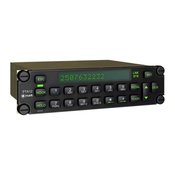
Hook switch control and indication is provided on the front panel. The hook switch may be controlled and its status viewed from a location remote to the PTA12-100 front panel. Ring indication is also provided on the front panel with a flashing green LED. A flash key is provided on the front panel to interrupt the hook. -
Page 5: Specifications
PTA12-100 POTS Telephone Adapter with Display SM55-2 Installation and Operation Manual Specifications 1.4.1 Electrical Specifications Power Supply Power Input Voltage with reverse, over voltage and over current protection Input Voltage +30.3 Vdc (maximum) Normal Operation +27.5 Vdc (nominal) +22.0 Vdc (minimum) +18.0 Vdc (emergency) - Page 6 PTA12-100 POTS Telephone Adapter with Display SM55-2 Installation and Operation Manual Available Audio RX audio, Sidetone, DTMF sidetone Ringing tone (enabled or disabled externally) RX Audio See RX Audio in the Bidirectional Signals section for rated output level Sidetone Rated mic input yields rated phones output with rated TX mic audio set on TIP/RING and both front panel VOL control and S/T level potentiometer set to max.
- Page 7 PTA12-100 POTS Telephone Adapter with Display SM55-2 Installation and Operation Manual ≤9.0 Vdc @ 25 mA loop current DC Voltage ≤3 dB roll-off from 350 Hz to 3 kHz Frequency Response ≤5% THD Distortion ≤ -50 dB from rated output (no signal)
-
Page 8: Physical Specifications
PTA12-100 POTS Telephone Adapter with Display SM55-2 Installation and Operation Manual HLD (Hold Status) On Hold LED on Off Hold LED off LNK (satcom link) Link Established LED on Link Down LED off SYS (satcom system) Available for Voice LED on... -
Page 9: Environmental Specifications
Humidity > 95% Vibration DO-160D Cat. [(SBM)(UF)] Qualification of the PTA12-100 POTS Telephone Adapter with Display was completed in accordance with DO-160D Env. Cat. A1/D1-BAB[(SBM)(UF)]XXXXXXZBABB[UUX]MXXXX. Note: Tested to DO-160D pre-change 1 and 2. Section 1 ends Section 1 Rev: 1.00... -
Page 10: Installation
Continued Airworthiness Maintenance of the PTA12-100 POTS Telephone Adapter with Display is ‘on condition’ only. Periodic maintenance of this product is not required. Section 2 Rev: 1.01... -
Page 11: Installation Procedures
Do not take a ground from the instrument panel or similar location that shares a ground return with a turn and bank, horizon or other motor driven instrument. This may cause the PTA12-100 unit to pick up the sound of the motor as ground loop interference.. 2.4.3... -
Page 12: Adjustments And Connections
2. Where the PTA12-100 is connected to an existing audio system, check that the PTA12-100 is properly selected when performing audio checks. Power up the aircraft’s systems and confirm normal operation of all functions of the PTA12-100. Refer to Section 3 (Operation) for specific operational details. -
Page 13: Accessories Required But Not Supplied
PTA12-100 POTS Telephone Adapter with Display SM55-2 Installation and Operation Manual Accessories Required But Not Supplied Installation kit p/n D25SV-IKC (crimp) is required to complete the installation. The kit consists of the following: Quantity Description NAT Part No. D-min 25 Socket Housing... -
Page 24: Operation
Hook switch control and indication is provided on the front panel. The hook switch may be controlled and its status viewed from a location remote to the PTA12-100 front panel. Ring indication is also provided on the front panel with a flashing green LED. A FLASH button is provided on the front panel to interrupt the hook. -
Page 25: Controls And Indicators
3.3.1 Display The PTA12-100 has a 16-character LED display, with each character block consisting of a 5x7 pixel matrix as shown in Figure 1. Display features depend on the status of the unit and are described in the relevant sections. - Page 26 LED also sends a signal to a further discrete output for a remote indicator (light bulb, etc.) if required. The hook switch may also be controlled by an external input. The HOOK button on the PTA12-100 front panel has master control of the hook switch control. When the PTA12-100 is configured for remote hook control and PTA12-100 has been selected by an audio panel TX selector, pressing the PTT for at least 0.5 second will active the hook switch (like pressing and releasing the HOOK button).
-
Page 27: Annunciators
The UP/DOWN arrow button is a momentary digital rocker switch used to increase and decrease the phones output volume when the PTA12-100 is in Call mode (i.e. the hook switch is active), or when the hook switch is inactive but the Ringer Detect circuit is active. -
Page 28: Name / Number Storage And Display
Name / Number Storage and Display The PTA12-100 can store up to 16 sets of data, each consisting of two lines: the first line has an identifier (address number) followed by a name and the second line is the associated telephone number. - Page 29 PTA12-100 POTS Telephone Adapter with Display SM55-2 Installation and Operation Manual 3.5.2 Recall Mode This mode is entered from Default mode by either buttoning in a valid number address (01 through 16) as described in Section 3.4, or by pressing the up/down arrow button.
- Page 30 PTA12-100 POTS Telephone Adapter with Display SM55-2 Installation and Operation Manual 3.5.3.1 Keypad Functions in Edit Mode In Edit mode (hook switch inactive) the keypad buttons do not provide DTMF tones. In Edit mode the lower text portion of these buttons is also implemented. This means that characters 0 through 9, A through Z, -, ., / and space are displayed when the corresponding button is pressed.
-
Page 31: Recall Mode
Edit mode returns the unit to Default Power-Up mode. Keypad Function Tables The PTA12-100 keypad buttons function differently depending on the current mode of the unit. A brief outline of the differences is given below as a quick reference guide. Table 1 shows Default and Recall modes and Table 2 shows Call and Edit modes. - Page 32 PTA12-100 POTS Telephone Adapter with Display SM55-2 Installation and Operation Manual Button Call Mode Function Edit Mode Function DTMF tone 1 transmitted and digit 1 displayed 1, -, ., or / displayed DTMF tone 2 transmitted and digit 2 displayed...
Need help?
Do you have a question about the PTA12-100 and is the answer not in the manual?
Questions and answers