Advertisement
TECHNICAL INFORMATION
ASSEMBLY, USE AND MAINTENANCE INSTRUCTIONS
HEATING UNITS
WITH ATMOSPHERIC BURNER
SERIE SR-UT SR-UT/K
Manual attached to the USE AND MAINTENANCE INSTRUCTIONS of the UT and UT/K series
As to what is not expressly mentioned in this manual, it is valid what is set forth in the manual ASSEMBLY USE AND
MAINTENANCE INSTRUCTIONS of the UT and UT/K series appliances
1
Advertisement
Table of Contents

Summary of Contents for Tecnoclima SR-UT Series
- Page 1 TECHNICAL INFORMATION ASSEMBLY, USE AND MAINTENANCE INSTRUCTIONS HEATING UNITS WITH ATMOSPHERIC BURNER SERIE SR-UT SR-UT/K Manual attached to the USE AND MAINTENANCE INSTRUCTIONS of the UT and UT/K series As to what is not expressly mentioned in this manual, it is valid what is set forth in the manual ASSEMBLY USE AND MAINTENANCE INSTRUCTIONS of the UT and UT/K series appliances...
- Page 2 GENERAL INFORMATION Dear Customer, Thank you for choosing a TECNOCLIMA product. This instruction handbook includes instructions and suggestions that shall be complied with for simpler installation and to ensure the best use of the appliance. Thank you. Tecnoclima S.p.A. COMPLIANCE AND PIN NUMBER The machine complies with the Directives, Rules and Regulations listed in the Declaration of Conformity that can be requested to the Producer.
- Page 3 GENERAL INFORMATION DESCRIPTION These machines are heating units to be used for air heating. They are essentially thermal units of exchange between the combustion products of an atmospheric burner and the air flow generated by a ventilation unit not included in the scope of supply. The air to be heated is sucked by the ventilation unit and, when it laps the hot surface of the heat exchanger, it is heated - increasing its temperature;...
-
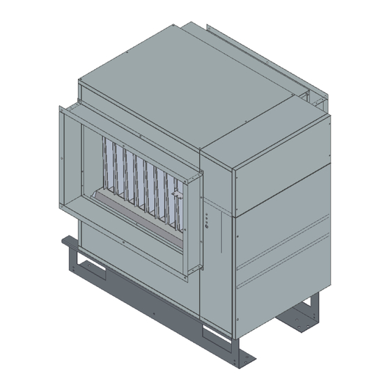
Page 4: Volume And Weight
GENERAL INFORMATION VOLUME AND WEIGHT TYPE 1-2-3-4-7-8-9-10: (This drawing represents the outdoor installation design) TYPE 4-10 TYPE Net weight TYPE Net weight... - Page 5 INSTALLATION AND SETTING INSTRUCTIONS VOLUME AND WEIGHT Type 5-6-11-12: (This drawing represents the outdoor installation design) TYPE 5-11 6-12 1300 1540 1260 1500 TYPE Net weight TIPO Net weight...
-
Page 6: Specific Technical Data
INSTALLATION AND SETTING INSTRUCTIONS SPECIFIC TECHNICAL DATA TYPE 4-10 5-11 6-12 ELECTRIC SUPPLY Single-phase 230V∼50Hz Three-phase 400V∼50Hz 3N MINIMUM AIR FLOW m³/h 1.820 2.920 4.130 5.900 7.900 8.750 USE LIMITS max. pressure +500 installation temperature °C -15/+40 suctioned air temperature °C -15/+30 1) Air flow shall be guaranteed by the Installer. -
Page 7: Original Accessories
INSTALLATION AND SETTING INSTRUCTIONS CONNECTION The electric and hydraulic connection is to be carried out in compliance with all the relevant Regulations and they should not be a hinder to the machine. SAFETY FLOW GAUGE To guarantee a correct machine operation it is required to install on the plant a device (e.g. air gauge) breaking burner operation in the event that air flow decreases beyond the minimum value set forth in section SPECIFIC TECHNICAL DATA. -
Page 8: Electric Connection
INSTALLATION AND SETTING INSTRUCTIONS TRANSFORMATION GAS / FORCED GAS BURNER Burners are factory-configured for operation with natural gas G20. The transformation, if required, to another type of fuel gas is installer’s responsibility and charge. Such transformation may be carried out only by qualified and skilled workers strictly observing the specifications set forth in the instruction manuals of the burner and of the power ramp, if any, provided together with them. -
Page 9: Fan Motor Control
INSTALLATION AND SETTING INSTRUCTIONS FAN MOTOR CONTROL In the electric panel there is an outlet for fan motor (MV) control. If the applied electric load is lower than that shown in the table set forth hereunder, such outlet can be used directly;... -
Page 10: Maintenance
TECHNICAL ASSISTANCE INSTRUCTIONS MAINTENANCE Periodic cleaning and maintenance operations are to be performed to preserve the equipment and ensure its correct functioning. These operations are to be performed by skilled and trained personnel, who have to start working when the equipment has cooled down and after disconnecting the electric and fuel supply. Periodically check the screws, used in the equipment assembly, to make sure they are tight and correctly fixed. -
Page 11: Combustion Analysis
IGNITION AND IONISATION ELECTRODES For a proper ignition and operation of the appliance it is important to verify the exact position of ignition and ionisation electrodes. Particularly, make sure that the ignition discharge takes place at the level of the burner tubular slits at a distance of 3-4 mm. - Page 12 38057 PERGINE VALSUGANA (TRENTO) ITALY Viale dell’Industria, 19 tel. (0461) 53 16 76 fax (0461) 51 24 32 www.tecnoclimaspa.com tecnoclima@tecnoclimaspa.com Since our Company is constantly committed to improve its products, their esthetical features, size, technical data, fittings, and additional devices might change. 05/13_Rev.0...
Need help?
Do you have a question about the SR-UT Series and is the answer not in the manual?
Questions and answers