Table of Contents
Advertisement
BARKO
LOADERS
NOTE: The operating, service and safety instructions for a Slasher Saw, Delimber or Topping Saw are
not included in this manual. See manufacturer's information.
NOTE: The Grapple Service and Installation Information is not included in this manual. See separate
Grapple Service and Installation manual which accompanies all grapples from the factory.
OPERATORS: 800-00050
081413
SERVICE MANUAL
595ML MAGNUM CRAWLER
Machine
Serial Number
The information and illustrations in this manual have
been approved as accurate at the time of printing.
However, the manual may contain information on
options not present on your loader. The right is reserved
by Barko Hydraulics,LLC to make changes and
improvements in its product at any time without notice
or obligation.
B A R K O
H Y D R A U L I C S ,
mailing: PO Box 16227, Duluth, MN 55816 shipping: 1 Banks Avenue, Superior, WI 54880
phone: 715-392-5641 fax: 715-392-3931
website: www.barko.com email: barkohydraulics@barko.com
PARTS: 800-00111
L L C
SERVICE: 800-00177
Advertisement
Table of Contents
Troubleshooting

Subscribe to Our Youtube Channel
Related Manuals for Barko Hydraulics 595ML

Summary of Contents for Barko Hydraulics 595ML
- Page 1 However, the manual may contain information on options not present on your loader. The right is reserved by Barko Hydraulics,LLC to make changes and improvements in its product at any time without notice or obligation.
-
Page 2: Table Of Contents
TABLE OF CONTENTS C. Electrical System Maintenance ......44 INTRODUCTION ............3 Electrical System Maintenance ......45 Introduction ............4 Electrical System Description ......45 Abbreviations and Symbols ......... 5 Electrical System Inspection ......45 Hydraulic Pressure Warning Sheet ...... 6 Battery Disconnect Switch ....... - Page 3 Marker 595 ML CRL (S) page 3 800-00177...
-
Page 4: Introduction
Model No. Website: www.barko.com Serial No. NOTE: Information in this manual is current at the time of printing. Barko Hydraulics reserves the right to make changes and improvements to it's products and manuals at any time without notice or obligation. -
Page 5: Abbreviations And Symbols
ABBREVIATIONS AND SYMBOLS air conditioner number Articulated Carrier (Art. Car.) Not Sold Separately opt. optional adj. adjust or adjusting appl. application page quart As Required assy assembly RH (rh) right hand Back of Cab sec. secondary see sep. ill. see separate illustration (means: bill of material brg. -
Page 6: Hydraulic Pressure Warning Sheet
Pressures in excess of these settings render each and all Barko warranties null and void and constitute an obvious misuse and abuse of our product. BARKO HYDRAULICS, LLC 595 ML CRL (S) page 6 800-00177... -
Page 7: Warranty
WARRANTY BARKO HYDRAULICS, LLC BARKO HYDRAULICS, L.L.C. ("Barko") warrants to the Distributor and/or original Buyer each new hydraulic knuckle boom loader, mulcher tractor or other product in BARKO's Equipment Group including attachments and accessories thereto, ("Product") sold by BARKO to be free from defects in material and workmanship under normal use, maintenance and service, as follows:... -
Page 8: Know Your Machine
KNOW YOUR MACHINE The following is a list of ten important safety precautions and warnings you should read through and understand before operating or servicing your machine. 1. Don't assume that because you know the control functions of other similar machinery, that you can run and/or service the Barko Loader. -
Page 9: Safety Summary
SAFETY SUMMARY Failure to follow safety precautions in this manual can result in death, severe personal injury and/or property damage. Carefully read safety precautions below and within this manual. Heed all decals on machine. DANGER - Indicates an immediate hazard which WILL result in severe personal injury or death. WARNING - Indicates a hazard or unsafe practice which COULD result in severe personal injury or death. - Page 10 SAFETY SUMMARY CONTINUED... WARNING DANGER If machine malfunctions during operation, stop Falling boom or load will cause death or severe machine motion as quickly as possible, lower injury. Stay clear if boom or load are not boom to the ground and shut down the machine. grounded.
- Page 11 SAFETY SUMMARY CONTINUED... WARNING WARNING High pressure hydraulic fluid can penetrate skin Improper load handling and/or hydraulic causing death, gangrene or other severe injury. pressure loss can cause load to impact cab Seek immediate medical help to remove fluid. guard, resulting in death or severe injury. Keep hands and body away from areas Do not rely on guard alone for personal ejecting fluid.
- Page 12 SAFETY SUMMARY CONTINUED... WARNING WARNING Always wear seat belt when operating or running If this machine is equipped with electric motor machine. driven Auxiliary Oil Cooler, be sure battery is disconnected before going near cooler fan. If battery is not disconnected, fan may come on at any time causing severe injury.
- Page 13 SAFETY SUMMARY CONTINUED... WARNING WARNING Do not exceed 15 PSI nozzle pressure when Use caution when checking items beyond your drying parts with compressed air. Do not direct reach. Use an approved safety ladder. compressed air against human skin. Serious injury could result.
-
Page 14: Fire Prevention
FIRE PREVENTION This machine may have several components which are at high temperatures under normal operating conditions, such as the engine, exhaust system, brake system and transmission. Clean the machine often. High pressure washing of the machine is suggested every 1000 hours (or 6 months) and always after a spill. -
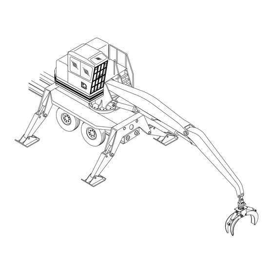
Page 15: Model Description
MODEL DESCRIPTION Hydraulic Reservoir Shrouding Main Power Unit & Boom Pumps Platform/Control Deck Air Cleaner Head Hood Stick Boom Assembly Exhaust Pipe Stick Boom Cylinder Grapple Grapple Hanger Rotator Main Boom Cylinder Grapple Cylinders Turntable Bearing Grapple Arms Swing Moor &... -
Page 16: Maintenance
A. PREVENTIVE MAINTENANCE 595 ML CRL (S) page 16 800-00177... -
Page 17: Safety While Servicing
WARNING WARNING Do not weld on any structural member unless specifically authorized by Barko Hydraulics. Any Relieve all hydraulic pressure before breaking any unauthorized welding or welding procedures will hydraulic connection, opening the reservoir access... -
Page 18: Preventive Maintenance
PREVENTIVE MAINTENANCE Preventive maintenance is really just a simple matter of common sense. If you keep any piece of mechanical equipment clean and properly lubricated, and promptly replace any worn or damaged parts, you are going to "prevent" deterioration and promote long life and safe, productive service. The only other requisite to such a program is the regular scheduling of such maintenance. -
Page 19: Service Schedule
SERVICE SCHEDULE 8 hours 50 hours 100 hours 400 hours 1000 hrs Yearly SERVICE REQUIRED Daily Weekly Monthly 2 Months 6 Months Hydraulic Reservoir - check level and quality of oil. Fuel Tank - Check level and fill if necessary. Engine Crankcase Oil - Check level. - Page 20 SERVICE SCHEDULE CONTINUED... 8 hours 50 hours 100 hours 400 hours 1000 hrs Yearly SERVICE REQUIRED Daily Weekly Monthly 2 Months 6 Months Hydraulic Oil Filter - On new machines the filter element should be replaced first at 100hrs. and then at 400 hrs.
- Page 21 SERVICE SCHEDULE CONTINUED... CRAWLER LOWER SERVICE SCHEDULE 8 hours 50 hours 100 hours 400 hours 1000 hrs SERVICE REQUIRED Yearly Daily Weekly Monthly 2 Months 6 Months Tracks - Inspect for damaged shoes/missing or loose bolts. Check master link for missing/loose bolts. Inspect links for missing/leaking oil plugs.
-
Page 22: Lubrication Points
LUBRICATION POINTS (PERFORM DAILY) Grapple Arms Main Boom Pivot GREASE Grapple Rotator Main Boom Cylinder Grapple Cylinders Stick Boom Cylinder Grapple Hanger (2 fittings) 10 Hydraulic Oil Reservoir HYDRAULIC Turntable Bearing & Pinion 11 Swing Motor Gearboxes Stick Boom Pivot 12 Crawler Final Drive GEAR FLUID OR ENGINE... -
Page 23: Fluid Specifications
FLUID SPECIFICATIONS GREASE Use grease shown on chart below, depending on the expected air temperature range. AIR TEMPERATURE RANGE Fahrenheit (F) 104 122 Celsius (C) NLGI NO. 2 HIGH TEMP. /EP NLGI O OR I ARCTIC GREASE HYDRAULIC OIL The following lists some features to look for in an oil. The hydraulic oil for the machine should feature: - Rust resistant additives to prevent rust formation from moisture condensation. - Page 24 FLUID SPECIFICATIONS CONTINUED... FUEL STORAGE NOTE: Diesel fuels stored for a long time may form gum or bacteria and plug filters. Keep fuel in a clean container and store in a protected area. Water and sediment must be removed before fuel gets to the engine.
-
Page 25: Special Torque Specifications
SPECIAL TORQUE SPECIFICATIONS WARNING Loose or overtorqued bolts can cause death, severe injury, or property damage. Maintain proper bolt torque. Visually check bolts daily. Check torque every 100 hours. WARNING In critical applications (such as Turntable Bearing Bolts and any grade 8 or grade 9 bolts), once the old bolts and nuts have been loosened, they must be replaced rather than re-tightened and re-torqued. -
Page 26: General Torque Specifications
GENERAL TORQUE SPECIFICATIONS See Special Torque Specifications that pertain specifically to this machine. LUBRICATED DIA. WARNING COARSE FINE FINE COARSE Grade 9 bolts must be used with Grade 9 washers. 5/16 7/16 WARNING Do not re-use grade 8 or grade 9/16 GRADE 5 9 bolts or nuts - replace with... -
Page 27: Hydraulic System
B. HYDRAULIC SYSTEM 595 ML CRL (S) page 27 800-00177... -
Page 28: Hydraulic Pressure Settings (595 Ml Crl)
HYDRAULIC PRESSURE SETTINGS (595 ML CRL) See the Service Manual for this machine for more specific information. RELIEF VALVES The Relief Valve portion of the control valves in your Barko Loader limit the flow of hydraulic oil, which relieves the excess pressure in the hydraulic system, if for any reason pressure is built up above a predetermined, safe, maximum. -
Page 29: Hydraulic Pressure Adjustment
HYDRAULIC PRESSURE ADJUSTMENT (AA11V-095-095) ADJUSTING TRACK PRESSURE (4500 PSI) AND STANDBY PRESSURE (425 PSI) Note: When setting the track pressure and standby pressure on a double pump system the two pumps must be set at equal pressures for optimal efficiency. The pressure readings from the pump output test port, or the system pressure output test port is the highest pressure from the either pump. -
Page 30: Pump Adjustment Crl (Sauer Tandem)
PUMP ADJUSTMENT CRL (SAUER TANDEM) (SAUER - SERIES 45 - 100/100) Pressure adjustments at the pump control the track drive; all other functions are controlled by the load sense manifold. 2. Install an electronic gauge on the PX system pressure test port located on the bulkhead to the right of the hydraulic pumps. -
Page 31: Sauer-Danfoss Plus1 Module
SAUER-DANFOSS PLUS1 MODULE Horsepower Limiting Adjustment The point at which the Plus1 module begins to limit engine horsepower can be adjusted via the trim potentiometer on the Plus1 wiring harness. The horsepower limiting can be adjusted to engage when the engine load reaches between 80% and 90%. -
Page 32: K170 Upper Valve Adjustments
HYDRAULIC PRESSURE ADJUSTMENT CONTINUED... K170 UPPER VALVE ADJUSTMENTS NOTE: The Pilot Filter must be removed and cleaned every 1000 hours. Main Relief - 5000 PSI non-adjustable. Pilot Relief - PSI non-adjustable. Port Reliefs for all boom and swing functions are non-adjustable. Grapple functions are equipped with adjustable feed reducers. - Page 33 HYDRAULIC PRESSURE ADJUSTMENT CONTINUED... (558-01699) 595 ML CRL (S) page 33 800-00177...
- Page 34 HYDRAULIC PRESSURE ADJUSTMENT CONTINUED... ADJUSTING UPPER (BOOM) PRESSURE (3600 PSI) 1. Pressure adjustment is made on load sense relief valve. 2. Remove acorn nut. 3. Adjust pressure by turning screw in or out with 5/32"" allen wrench, clockwise rotation increases pressure, counter clockwise rotation decreases pressure.
-
Page 35: Hydraulic Reservoir Maintenance
HYDRAULIC RESERVOIR MAINTENANCE The supply source for the hydraulic system, the oil DRAINING THE RESERVOIR reservoir, is located behind the cab. A sight gauge for 1. First, be sure boom is lowered to the ground and checking oil level is located on the reservoir inside the secure. -
Page 36: Hydraulic Filter Maintenance
HYDRAULIC FILTER MAINTENANCE NOTE: On a new machine the filter elements must be changed after the first 100 hours of operating time and then every 400 hours after that. THE RETURN FILTER (See Figure 1) The Return Filters (565-00116) are welded into the top of the hydraulic oil reservoir. The filter heads must be unbolted, twisted, and lifted off to reveal the filter element which can then be removed and replaced. - Page 37 HYDRAULIC FILTER MAINTENANCE CONTINUED... 5. Screw element on by hand until tight, to seat gasket in groove. 6. Loosen element. 7. Retighten element until it contacts gasket, then tighten 1/2 to 3/4 of a turn. 8. Check for leaks after start-up. FILTER HEAD GASKET FILTER...
-
Page 38: Eliminating Air From The System
ELIMINATING AIR FROM THE SYSTEM All hydraulic fluid contains some dissolved air, usually about 10% by volume. Under increased pressure, the fluid will absorb much more air. Aeration in a hydraulic circuit is the presence of free air in places where there ought to be only fluid. -
Page 39: Hydraulic Fittings, Hoses & Tubing
HYDRAULIC FITTINGS, HOSES & TUBING A heavy wall tubing and multi-wire hose network carries the hydraulic oil from the reservoir to the pumps and valves and then to cylinders and motors and finally back to the reservoir. Operating pressure of the hydraulic system varies from model to model. For your loader, consult the Hydraulic Pressure Warning Sheet in this manual. -
Page 40: Hydraulic Cylinder Maintenance
HYDRAULIC CYLINDER MAINTENANCE Hydraulic cylinders provide force used to operate booms, attachment, and stabilizers. Proper maintenance of cylinders will promote long life and smooth operation. Inspect cylinders daily for leaks or damage and repair or replace as necessary. Lubricate cylinder grease fittings daily. - Page 41 Piston and Gland shown may not be type used on your machine but are shown as a reference. Piston SEAL PLIERS (PART # 412-00409) BEING USED TO BEND SEAL FOR INSTALLATION. Gland NOTE: Follow order and orientation of seals shown in drawing.
-
Page 42: Swing Motor Gearbox Maintenance (1010D)
SWING MOTOR GEARBOX MAINTENANCE (1010D) CHECKING FLUID LEVELS A lube reservoir is connected to the gearbox with a hose. Check that the lube reservoir is at half full before operating. (Gearboxes are also equipped with a see-through breather and/or steel/magnetic plugs to check oil level.) FILLING THE GEARBOX WITH FLUID To fill the gearbox with fluid, keep adding fluid to the lube reservoir until gearbox is full and lube reservoir remains at half full. -
Page 43: Attaching Slasher Saw
ATTACHING SLASHER SAW When attaching a slasher saw refer to the following diagrams for proper wiring and hose placement. Wire # 14 Wire # 12 Wire # 6 Wire # 13 Knives Open Slasher Down Slasher Up Knives Close Wire # 5 Wire # 11 Topping Saw Up Topping Saw Down... -
Page 44: Electrical System Maintenance
C. ELECTRICAL SYSTEM MAINTENANCE 595 ML CRL (S) page 44 800-00177... -
Page 45: Electrical System Maintenance
ELECTRICAL SYSTEM MAINTENANCE ELECTRICAL SYSTEM DESCRIPTION This machine has 12 Volt electrical system with alternator, negative ground, and 12 Volt battery. There are two basic circuits in the electrical system: 1. Charging circuit (alternator and battery). 2. Starting circuit (switch, solenoid, battery, and starter). NOTE: Disconnect battery ground cable before making any repairs to electrical circuits. -
Page 46: Using An Extra Battery To Start Machine
ELECTRICAL SYSTEM MAINTENANCE CONTINUED... USING AN EXTRA BATTERY TO START MACHINE If necessary to use an extra battery and "jumper" cables to start engine, be careful. This is a two-person operation. There must be one person in operator's seat and one person to connect and disconnect battery cables. WARNING Lead-acid batteries produce flammable and explosive gases. -
Page 47: Installing A New Battery
ELECTRICAL SYSTEM MAINTENANCE CONTINUED... INSTALLING A NEW BATTERY 1. Remove battery cables. Remember position of positive terminal and negative terminal so you can connect them again correctly. 2. Remove battery hold-down bar. Remove battery from compartment. 3. Clean terminal posts of new battery and cable connections with wire brush. 4. - Page 48 ELECTRICAL SYSTEM MAINTENANCE CONTINUED... 3. If any of these tests show zero voltage, repair or replace wiring. 4. Check voltage again until correct reading appears. CHECKING ALTERNATOR OUTPUT 1. Disconnect negative battery cable. 2. Remove wire from "BAT" connector on alternator and fasten it to one connector of an ammeter. Fasten other connector of ammeter to "BAT"...
-
Page 49: Trouble Shooting The Electrical System
ELECTRICAL SYSTEM MAINTENANCE CONTINUED... TROUBLE SHOOTING THE ELECTRICAL SYSTEM The following trouble shooting chart is provided as an assistance in locating and correcting problems which are most common. PROBLEM CAUSE Battery does not hold it's charge. 1, 2, 3, 4, 5 Alternator will not charge. -
Page 50: Electric Collector Maintenance
ELECTRIC COLLECTOR MAINTENANCE Hex Lock Nuts Acorn Nut Nylon Rub Disk Cap Screw Cover Set Screw-Type Connectors Brush Holding Stud Knife Disconnect Terminals Outboard Bearing (nylon) with Plastic Sleeves Brush/Arm/Spring Assemblies Set Collar (socket screw-type) Core Assembly (has brass rings that brushes ride on) Nylon Bearing Base Bracket... - Page 51 ELECTRIC COLLECTOR MAINTENANCE CONTINUED... COLLECTOR INSTALLATION WARNING Do not remove collector cover or attempt maintenance until power is disconnected and locked. Electrocution may occur. 1. Fasten the collector mounting tube to the stationary member of the equipment it is to be used on. 2.
- Page 52 ELECTRIC COLLECTOR MAINTENANCE CONTINUED... BRUSH ASSEMBLY REPLACEMENT WARNING Do not remove collector cover or attempt maintenance until power is disconnected and locked. Electrocution may occur. 1. Remove the hex lock nuts and washers at the top of the brush holding stud along with the outboard bearing, if used.
-
Page 53: Air Conditioner Maintenance
AIR CONDITIONER MAINTENANCE Hot High Pressure Gas Low Pressure Gas (suction side) Cold Low Pressure Gas Outside Air Flow Cab Air Flow (under seat in cab) (on engine) Metered Refrigerant (near engine radiator) (under seat in cab) High Pressure Liquid Thermostat (under cab next to engine ) Air Conditioner components are shown above connected together to illustrate system operation. -
Page 54: Checking/Adding Refrigerant
AIR CONDITIONER MAINTENANCE CONTINUED... CHECKING/ADDING REFRIGERANT Allow only certified personnel to service the heater/air conditioner system. The chart below shows relative temperatures and pressures for the system. Generally, for most Barko machines, 3 pounds of refrigerant is required for the system to operate properly. However, use the chart below to determine the exact amount. -
Page 55: Air Conditioner Trouble Shooting
AIR CONDITIONER MAINTENANCE CONTINUED... AIR CONDITIONER TROUBLE SHOOTING To display diagnostics depress the ON key three times. The digital display will then display any active fault codes. Pressing the ON again will scroll through any existing error codes. Fault Codes: No Faults ............ - Page 56 AIR CONDITIONER MAINTENANCE CONTINUED... Problem: Evaporator Core Icing Up (Freezing Up) Evaporator Probe (2-pin black connector) 1. Set the control temperature to a low value. Verify that the compressor is on. Pull the probe and place is in a bath of ice water. Compressor should turn off. If not, bump up the control temperature a few degrees and try again.
- Page 57 AIR CONDITIONER MAINTENANCE CONTINUED... ATC CONTROLLER RFI INTERFERENCE It has been discovered that the Programmable Control Panel may have some RFI interference that causes the panel to change programs. This does not happen on all units. We have a choke RFI filter available. If your system does not have the choke filter, install the filter as shown in the photos below.
- Page 58 AIR CONDITIONER MAINTENANCE CONTINUED... INSTRUCTIONS FOR ADVANCED DIAGNOSTICS ATC SYSTEM AND PROGRAMMING (Programming and Advanced Diagnostics Only on New StyleDiagnostics Only on Old Style) Error code display is accessed by pressing the “ON” key three times quickly. Press the “ON” key to cycle through all of the active error codes. Wait five seconds to return to normal display mode.
- Page 59 AIR CONDITIONER MAINTENANCE CONTINUED... A9: No Connection A10: No Connection A11: No Connection A12: No Connection B1: Cab Temperature Signal for 30K Thermistor B2: Cab Temperature Ground B3: Ambient Temperature Signal B4: Water Valve Feedback Signal B5: No Connection B6: No Connection B7: Serial + Connection to Control Panel B8: Serial –...
- Page 60 AIR CONDITIONER MAINTENANCE CONTINUED... Programming 1) Turn on. 2) Error code display mode is accessed by pressing the “ON” key three times quickly. 3) The advanced diagnostics display mode is activated by pressing and holding the “ON” key for five seconds while the error code display is active – CAb will display. 4) The parameter function is activated by pressing and holding the “OFF”...
- Page 61 AIR CONDITIONER MAINTENANCE CONTINUED... Press the “FAN UP”/”FAN DOWN” keys to select a config setting. Press the “TEMP UP”/”TEMP DOWN” keys to change the selected setting. Barko Programming P0 – 1 P1 – 2 P2 – 1 P3 – 4 P4 –...
- Page 62 AIR CONDITIONER MAINTENANCE CONTINUED... 5) Turn off when done programming. 6) Check error code display by pressing the "on" key three times quickly Should read "EQ" 595 ML CRL (S) page 62 800-00177...
-
Page 63: Air Conditioner Charging
AIR CONDITIONER MAINTENANCE CONTINUED... AIR CONDITIONER CHARGING Safety Precautions & Warnings: 1) Charging of an air conditioning system should be conducted by a qualified a/c technician. 2) Always wear the proper protective eyewear and clothing before working on any air conditioning system. 3) Always wear work gloves when working with condensers or evaporators. - Page 64 AIR CONDITIONER MAINTENANCE CONTINUED... Field Charging Procedure: 1) Insure all fittings are tight and components installed correctly. 2) Attach manifold gauge set to high and low side service ports. The blue coupler attaches to low pressure charge port and red coupler attaches to high pressure charge port. 3) Attach yellow (center) hose from manifold gauge set to vacuum pump.
- Page 65 AIR CONDITIONER MAINTENANCE CONTINUED... 17) Turn refrigerant tank right side up on charging scale (vapor charge position). 18) Start machine engine and turn on a/c system. 19) Record ambient temperature, evaporator inlet temperature, evaporator air outlet temperature, suction pressure and discharge pressure. 20) If suction pressure is 5 psig or less, keep engine speed at idle until additional refrigerant has been added and suction pressure exceeds 5 psig.
- Page 66 AIR CONDITIONER MAINTENANCE CONTINUED... Typical Manifold Gauge Set PRESSURE TEMPERATURE CHART °F °C HFC 134a CFC-12 °F °C HFC 134a CFC-12 -51.1 21.8 19.0 12.8 51.1 52.0 -48.3 20.4 17.3 15.6 57.3 57.7 -45.6 18.7 15.4 18.3 63.9 63.8 -42.8 16.9 13.3 21.1...
-
Page 67: Power Unit Maintenance
D. POWER UNIT MAINTENANCE 595 ML CRL (S) page 67 800-00177... -
Page 68: Engine Maintenance
ENGINE MAINTENANCE The standard source of power for the hydraulic system in this machine is a Cummins or John Deere diesel engine. Complete specifications, operating instructions, and maintenance and lubrication information will be found in the engine manufacturer's manuals which ship with the machine. These manuals may also include information on other, similar, engines. -
Page 69: Pump Drive Maintenance
PUMP DRIVE MAINTENANCE (FOR FUNK PUMP DRIVES) TWO, THREE AND FOUR PAD PUMP DRIVES 2 PAD PUMP DRIVE 3 PAD PUMP DRIVE 4 PAD PUMP DRIVE Figure 1 LUBRICANT RECOMMENDATIONS AND FLUID CHANGING PROCEDURES Lubricant Type: EP 80-90 gear fluid (except for direct drive models). Lubricant Grade: Weather Temperature Below -10 degrees F (-23 degrees C) - Page 70 PUMP DRIVE MAINTENANCE CONTINUED... 6. Clean all magnetic drain plugs before replacing. 7. Always use clean fluid in clean containers. 8. Do not overfill. This will result in overheating and possible malfunction of the unit. 9. Fill with EP 80-90 gear fluid (until fluid comes back out of the fill hole). Do not overfill! 10.
- Page 71 PUMP DRIVE MAINTENANCE CONTINUED... NOTE: Drive in direction of arrow. 8. To remove bearings from gear hubs, use gear puller or Arbor Press. REASSEMBLY OF PUMP DRIVE For reassembly, use the reverse procedure of 1 through 8. NOTE: Plastic cord used for gasket material under pump adaptor plates and input housing is not reusable. Replace with new material when reassembling.
-
Page 72: Single Pad Pump Drives
PUMP DRIVE MAINTENANCE CONTINUED... SINGLE PAD PUMP DRIVES This type of Pump Drive (See Figure 4), is mounted to the engine, and is virtually maintenance free. Figure 4 If a Disconnect Clutch (optional) is ordered on your machine, the following maintenance must be done. DISCONNECT CLUTCH (OPTIONAL) If clutch does not pull, heats, or operating lever jumps out, adjustment is required. -
Page 73: Air Cleaner Maintenance
AIR CLEANER MAINTENANCE Proper air cleaner servicing will result in maximum engine protection against the ravages of dust. Proper servicing can also save you time and money by increasing filter life and dust cleaning efficiency. Two of the most common servicing problems are: 1. - Page 74 AIR CLEANER MAINTENANCE CONTINUED... AIR CLEANERS WITH VACUATOR VALVE On vacuator valve equipped models, (see figure 3) DUST CUP dust cup service is cut to a minimum. A quick check to see that the vacuator valve is not inverted, damaged, or plugged is all that is necessary. VACUATOR VALVE Figure 3 CHECKING AIR CLEANER RESTRICTION...
- Page 75 AIR CLEANER MAINTENANCE CONTINUED... IMPORTANT STEPS TO FOLLOW EVERY TIME AN AIR CLEANER ELEMENT IS REPLACED: 1 REMOVE THE 5 PRESS YOUR OLD ELEMENT FRESH GASKET AS GENTLY TO SEE IF IT AS POSSIBLE SPRINGS BACK Loosen wing nut and remove old element. Baby Make sure your new element is made with a that dirty element until you get it clear out of the highly compressible gasket that springs...
- Page 76 AIR CLEANER MAINTENANCE CONTINUED... THE IMPORTANT "DON'TS" TO ALWAYS REMEMBER: DON'T REMOVE ELEMENT FOR DON'T INPECTION OVERLOOK A WORN OR Such a check will always do more harm to your DAMAGED GASKET engine than good. Ridges of dirt on the gasket IN THE HOUSING sealing surface can drop on the clean filter side when the gasket is released.
-
Page 77: Structural Maintenance
E. STRUCTURAL MAINTENANCE 595 ML CRL (S) page 77 800-00177... -
Page 78: Turntable Bearing Maintenance
TURNTABLE BEARING MAINTENANCE WARNING The turntable bearing area is a potential pinch point. Before doing any maintenance or inspection on turntable bearing, lower boom and attachment to the ground, shut machine down to a zero energy state and put ignition key in your pocket. - Page 79 TURNTABLE BEARING MAINTENANCE CONTINUED... Figure 1 1. Take measurements at 8 equally spaced locations on the bearing. See Figure 2. 2. Rotate machines upper works so that the centerline of the boom is aligned with the first measuring location and the centerline of the counterweight is aligned with another measuring location.
- Page 80 TURNTABLE BEARING MAINTENANCE CONTINUED... TABLE 1 Maximum Allowable Clearances (inches) for 3000 Series Ball Bearings Ball Diameter Up To: 1-1/4 1-3/8 1-1/2 1-3/4 2-1/4 2-1/2 2-3/4 Ball Path Diameter .055 .055 .055 .059 .067 .075 .083 .098 Up To: .059 .059 .063 .067...
- Page 81 TURNTABLE BEARING MAINTENANCE CONTINUED... INSPECTING THE TURNTABLE BEARING WARNING The turntable bearing area is a potential pinch point. Before doing any maintenance or inspection on turntable bearing, lower boom and attachment to the ground, shut machine down to a zero energy state and put ignition key in your pocket. WARNING Do not operate machine with a bearing that is worn out, damaged or has reached maximum permissable clearance measurements.
-
Page 82: Crawler Maintenance
CRAWLER MAINTENANCE FILLING/CHECKING TRANSMISSION OIL When checking the transmission oil the transmission should be in the orientation shown below with the drain plug (2) in the 6 o'clock position. This results in the filler plug (1) being in the 10 o'clock or 2 o'clock position. Fill the oil up to the height of the filler hole. - Page 83 CRALWER MAINTENANCE CONTINUED REMOVING THE CRALWER TRACK Position the track so that the master pin is within the lower section of the front idler. Secure grouser shoe with wooden block against falling out after opening the track. Remove tension in track by slowly and carefully unscrewing the grease nipple a few turns untill grease begins to come out, WARNING: Do not completly unscrew grease nipple.
- Page 84 Marker Marker Marker 595 ML CRL (S) page 84 800-00177...
-
Page 85: Trouble Shooting
TROUBLE SHOOTING Use this section only as a general guide to finding solutions for machine problems. If the machine should malfunction, find the problem in the headings listed then refer to the possible causes and remedies listed with the problem. The list of problems, causes, and remedies will only give an indication of where a possible problem can be and what repairs are needed. -
Page 86: Hydraulic System
TROUBLE SHOOTING CONTINUED... HYDRAULIC SYSTEM PROBLEM REMEDY CAUSE Pump or motor too noisy. Low hydraulic oil supply or wrong Fill hydraulic reservoir with proper viscosity. oil. Air in hydraulic oil. Check for foamy oil. Tighten connections, replace o-rings or lines. Hydraulic oil dirty or low supply. -
Page 87: Electrical System
TROUBLE SHOOTING CONTINUED... HYDRAULIC SYSTEM CONTINUED... PROBLEM REMEDY CAUSE No machine functions. Low hydraulic oil level. Fill hydraulic reservoir with proper oil. Plugged suction line. Clean or replace strainer. ELECTRICAL SYSTEM PROBLEM CAUSE REMEDY Battery will not charge. Loose or corroded connection. Clean and tighten battery connections. -
Page 88: Machine Operations
TROUBLE SHOOTING CONTINUED... MACHINE OPERATIONS PROBLEM REMEDY CAUSE Boom will not remain raised. Replace valve. Main or Secondary boom valve needs service. Any or all of the following: No oil flow or pressure. No servo pressure. - Replace dirty filters. - Fill reservoir to proper level. -
Page 89: Decals
Date of Change. 539-01026 DECAL, "BARKO" (8") (on each side of main boom) to 10-1-07 beige w/ orange shadow 539-01029 DECAL, "595ML" (on each side of main boom) to 10-1-07 beige w/ orange shadow 539-01088 DECAL, "BARKO" (8") (each side-main boom)
Need help?
Do you have a question about the 595ML and is the answer not in the manual?
Questions and answers