Table of Contents
Advertisement
Quick Links
Advertisement
Table of Contents
Troubleshooting

Related Manuals for Breathe LIFE2000


Summary of Contents for Breathe LIFE2000
- Page 1 BREATHE TECHNOLOGIES ® LIFE2000® VENTILATION SYSTEM Instructions for Use...
-
Page 2: Table Of Contents
CONTENTS CHAPTER 1: LIFE2000® VENTILATION SYSTEM INTRODUCTION ___________________________ 6 Indications for Use _______________________________________________________________________6 Symbols and Conventions __________________________________________________________________6 Safety Information ________________________________________________________________________7 Features ______________________________________________________________________________ 10 Packaging Contents _____________________________________________________________________ 11 System Components _____________________________________________________________________ 12 Ventilator _____________________________________________________________________________ 12 Compressor ___________________________________________________________________________ 13 Configurations _________________________________________________________________________ 14... - Page 3 Connecting an Interface to the Ventilator in Extended Range or Stand-Alone Configuration ________________ 51 The Breathe Universal Circuit™ Connector ____________________________________________________ 52 Connecting the Breathe Universal Circuit™ Connector to Third-Party Patient Masks or Tubes _______________53 Examples of Patient Mask and Tube Connections _______________________________________________53 The Breathe Pillows Interface™...
- Page 4 CONTENTS CHAPTER 6: VENTILATION SETTINGS ______________________________________________ 56 Introduction to Ventilation Settings _________________________________________________________ 56 Home Screen _________________________________________________________________________ 56 Moving Between the Home Screen and Menu Screen ____________________________________________57 Menu Screen __________________________________________________________________________57 Touch Screen Energy-Save Mode ___________________________________________________________58 Defining Clinical Settings __________________________________________________________________58 Accessing the Settings Menu ______________________________________________________________58 Accessing the Clinician’s Settings Menu _____________________________________________________ 59 Disabling Access to the Clinician’s Settings Menu ______________________________________________ 59 Prescription Settings ____________________________________________________________________ 60...
- Page 5 Alarm Checks _________________________________________________________________________ 109 Cleaning and Disinfecting the Ventilation System _______________________________________________ 109 Cleaning for Single Patient Use ____________________________________________________________ 110 Cleaning for Multi-Patient Use ______________________________________________________________ 111 Cleaning the Breathe Interfaces ___________________________________________________________ 112 Purging the Breathe Universal Circuit Connector and Breathe Pillows Interface™ ________________________113 ™...
- Page 6 CONTENTS CHAPTER 9: ACCESSORIES ______________________________________________________129 Battery Information _____________________________________________________________________ 129 Ventilator Battery Specifications ___________________________________________________________ 129 Compressor Battery Specifications _________________________________________________________ 129 Ventilator Battery Charger and Power Cord Specifications ________________________________________ 130 Compressor Power Supply and Power Cord Specifications _______________________________________ 130 Oxygen Monitor ________________________________________________________________________131 Exhalation Volume Monitor ________________________________________________________________131 Ventilator Altitude Volume Adjustment Table __________________________________________________ 132 Accessories and Replacement Parts ________________________________________________________ 133...
-
Page 7: Chapter 1: Life2000® Ventilation System Introduction
WARNING: Use the Breathe Technologies® Life2000® Ventilation System only for patients who meet the Indications for Use. If the ventilation system is used for patients that do not meet the Indications for Use, patients may not receive appropriate respiratory therapy. -
Page 8: Safety Information
LIFE2000 VENTILATION SYSTEM INTRODUCTION SAFETY INFORMATION Please read the following safety warnings and cautions in their entirety before using the Breathe Technologies® Life2000® Ventilation System. Warnings and cautions can also be found throughout this Instructions for Use. WARNING: • The Breathe Technologies® Life2000® Ventilation System is a restricted medical device intended for use by qualified, trained personnel under the direction of a physician. - Page 9 Doing any of these may damage the interfaces or hoses and impair gas delivery. • If using the Breathe Pillows Interface™, properly secure the patient interface to the face and route tubing around the ears to avoid strangulation.
- Page 10 • Use only the Breathe Technologies® approved battery charger and cord set with the ventilation system. If an unauthorized battery charger or cord set is used with the ventilation system the system may be damaged.
-
Page 11: Features
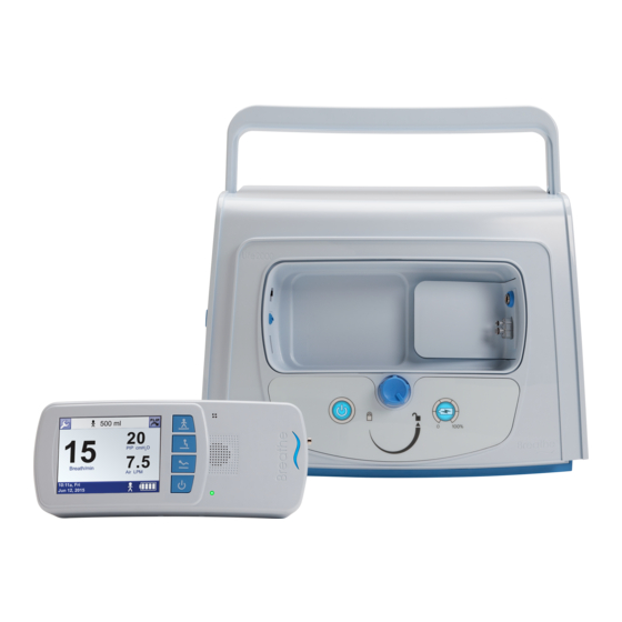
The Breathe Technologies® Life2000® Ventilation System is a critical care, volume control mechanical ventilation system designed for a broad range of applications in critical care and home settings. The modular Life2000® Ventilation System (system) is composed of the Life2000® Ventilator (ventilator) and the Life2000® Compressor (compressor). -
Page 12: Packaging Contents
The ventilation system is shipped in specially designed, protective boxes. Do not throw away the boxes; keep them for future transportation needs. Life2000® Ventilator (ventilator) The ventilator can be used with the Life2000® Compressor or an alternate 50-PSI pressure source. Life2000® Compressor (compressor) -
Page 13: System Components
LIFE2000 VENTILATION SYSTEM INTRODUCTION SYSTEM COMPONENTS VENTILATOR FRONT BOTTOM Battery charger connection Touch screen Interface connection Silence Alarm button Activity buttons 12 Gas inlet connection High Activity button For manufacturer’s use only Medium Activity button Low Activity button Power button for ventilator... -
Page 14: Compressor
LIFE2000 VENTILATION SYSTEM INTRODUCTION COMPRESSOR FRONT Ventilator docking cradle Power source indicator light Power button for compressor Locked icon (ventilator charging indicator light) Locking knob Unlocked icon Battery charge status button Battery charge indicator lights and battery charge scale SIDE... -
Page 15: Configurations
LIFE2000 VENTILATION SYSTEM INTRODUCTION CONFIGURATIONS The modular Life2000® Ventilation System (system) is composed of the Life2000® Ventilator (ventilator) and the Life2000® Compressor (compressor). The system can be used in three different configurations. STATIONARY CONFIGURATION The ventilator is docked into the compressor for ventilation while resting. For information about how to setup the ventilation system in this configuration, see the following chapter "Chapter 2: Stationary Configuration". -
Page 16: Chapter 2: Stationary Configuration
CHAPTER 2: STATIONARY CONFIGURATION INTRODUCTION TO STATIONARY CONFIGURATION In Stationary Configuration, the ventilator is docked into the compressor. The compressor provides the ventilator with a continuous pressure source and functions as a charging station. STATIONARY CONFIGURATION SETUP CHECKLIST Refer to the chapter contents for full instructions, warnings, and cautions. ☐... -
Page 17: Positioning And Carrying The Compressor
• The ventilator settings might not be achieved Observed Maximum Simulated Elevation when sourced by the Life2000 Compressor due ® Compressor Output (in feet) to increases in altitude near or above 2500 feet. -
Page 18: Supplying Power To The Compressor
Wet environments may damage the AC power cord or external power supply and may cause electric shock. • Use only the Breathe Technologies® approved AC power cord and external power supply with the compressor. Using an unauthorized AC power cord or external power supply may damage the compressor. -
Page 19: Docking The Ventilator Into The Compressor
STATIONARY CONFIGURATION DOCKING THE VENTILATOR INTO THE COMPRESSOR NOTE: When switching between ventilation system configurations, ensure that the patient receives adequate ventilation therapy; place the patient on an alternate means of ventilation if necessary. Ensure that the ventilator is powered off. NOTE: Alarms might be encountered and/or the selected Activity Button might be inadvertently changed if the ventilator is not... -
Page 20: Connecting An Interface To The Compressor
THE OUTLET FITTING IN STATIONARY CONFIGURATION Do not connect a gas source to the outlet fitting on the compressor. CAUTION: Using the outlet fitting while the Life2000 Ventilation System is delivering therapy in Stationary Configuration might decrease flow to the patient. -
Page 21: Powering On Sequence In Stationary Configuration
This self test can take up to 15 seconds to complete. If you do not hear tones when you turn on the ventilator, contact your Breathe Technologies® service representative. When the Home Screen is displayed, the touch screen is ready to use. -
Page 22: Checking The Compressor's Internal Battery Status
STATIONARY CONFIGURATION CHECKING THE COMPRESSOR’S INTERNAL BATTERY STATUS The compressor is equipped with an internal battery for temporary AC power disruptions. This internal battery: • charges when the compressor is attached to AC power. • has a maximum charge of one hour. When the compressor is powered on and the power source indicator lights surrounding the power button are illuminated in orange the compressor is running on its internal battery. - Page 23 STATIONARY CONFIGURATION COMPRESSOR BATTERY CHARGE STATUS When the compressor is powered on, the indicator lights in the battery charge scale are visible. When the compressor is powered off, press and hold the battery charge status button to display the battery charge scale indicator lights.
-
Page 24: Checking The Ventilator Battery Charge
STATIONARY CONFIGURATION CHECKING THE VENTILATOR BATTERY CHARGE The compressor and the ventilator are independent devices, each with its own internal battery. When the compressor is powered on, and the ventilator is properly docked and locked into the compressor in Stationary Configuration, the compressor functions as a charging station for the ventilator. -
Page 25: Silence Alarm Button On The Compressor
STATIONARY CONFIGURATION SILENCE ALARM BUTTON ON THE COMPRESSOR Silencing and clearing alarms is a multi-step process that depends on alarm priority and how many alarms are active. For more information see "Chapter 7: Alarms, Alerts, and Troubleshooting". Press the Silence Alarm button to temporarily silence the alarm for 60 seconds. -
Page 26: Powering Off Sequence In Stationary Configuration
STATIONARY CONFIGURATION POWERING OFF SEQUENCE IN STATIONARY CONFIGURATION To power off the compressor, press the Compressor Power button. To power off the ventilator, press the Ventilator Power button for three seconds until a confirmation screen appears. 100% To continue to power off the ventilator, choose OK. NOTE: If a selection is not made within 20 seconds or if the BACK button is selected, the previous screen will be displayed and the ventilation status will... -
Page 27: Chapter 3: Extended Range Configuration
CHAPTER 3: EXTENDED RANGE CONFIGURATION INTRODUCTION TO EXTENDED RANGE CONFIGURATION The Life2000® Ventilation System can be used in different configurations of operation as the patient’s needs change. In Extended Range Configuration, the ventilator is connected to the compressor with a Breathe Technologies oxygen hose to enable the activities of daily living. -
Page 28: Positioning And Carrying The Compressor
• The ventilator settings might not be achieved Observed Maximum Simulated Elevation when sourced by the Life2000 Compressor due ® Compressor Output (in feet) to increases in altitude near or above 2500 feet. -
Page 29: Supplying Power To The Compressor
Wet environments may damage the AC power cord or external power supply and may cause electric shock. • Use only the Breathe Technologies® approved AC power cord and external power supply with the compressor. Using an unauthorized AC power cord or external power supply may damage the compressor. -
Page 30: Undocking The Ventilator From The Compressor
EXTENDED RANGE CONFIGURATION 3 UNDOCKING THE VENTILATOR FROM THE COMPRESSOR NOTE: When switching between ventilation system configurations, ensure that the patient receives adequate ventilation therapy; place the patient on an alternate means of ventilation if necessary. Power off the ventilator. NOTE: Alarms might be encountered and/or the selected Activity Button might be inadvertently changed if the ventilator is not... -
Page 31: Connecting The Ventilator And Compressor In Extended Range Configuration
The interface, source gas supply hose, and power cords should be positioned to avoid restricting movement, causing a tripping hazard, or posing a strangulation risk. CAUTION: Use only a Breathe Technologies® oxygen hose with the ventilation system. NOTE: A 20-foot source gas supply hose (available to order) is recommended when using a ventilator output volume greater than 350 ml. -
Page 32: Connecting An Interface To The Ventilator In Extended Range Configuration
EXTENDED RANGE CONFIGURATION 3 CONNECTING AN INTERFACE TO THE VENTILATOR IN EXTENDED RANGE CONFIGURATION Plug the Breathe Pillows Interface™ or Breathe Universal Circuit connector ™ into the interface port on the bottom of the ventilator until it clicks. For more information about wearing interfaces, see "Chapter 5: Connecting an Interface"... -
Page 33: Powering On Sequence In Extended Range Configuration
This self test can take up to 15 seconds to complete. If you do not hear tones when you turn on the ventilator, contact your Breathe Technologies® service representative. When the Home Screen is displayed, the touch screen is ready to use. -
Page 34: Checking The Compressor's Internal Battery Status
EXTENDED RANGE CONFIGURATION 3 CHECKING THE COMPRESSOR’S INTERNAL BATTERY STATUS The compressor is equipped with an internal battery for temporary AC power disruptions. This internal battery: • charges when the compressor is attached to AC power. • has a maximum charge of one hour. When the compressor is powered on and the power source indicator lights surrounding the power button are illuminated in orange the compressor is running on its internal battery. - Page 35 EXTENDED RANGE CONFIGURATION COMPRESSOR BATTERY CHARGE STATUS When the compressor is powered on, the indicator lights in the battery charge scale are visible. When the compressor is powered off, press and hold the battery charge status button to display the battery charge scale indicator lights.
-
Page 36: Checking The Ventilator Battery Charge
EXTENDED RANGE CONFIGURATION 3 CHECKING THE VENTILATOR BATTERY CHARGE If you intend to use the ventilator on battery power, make sure that the battery is sufficiently charged for your duration of use. It takes approximately three to four hours to fully recharge the battery whether the ventilator is off or on. A fully charged battery should last up to four hours. -
Page 37: Assembling The Ventilator Battery Charger And Charging The Ventilator
• Use only the Breathe Technologies® approved battery charger and cord set with the ventilator. If an unauthorized battery charger or cord set is used with the ventilator, the ventilator may be damaged. -
Page 38: Securing The Ventilator
Always secure the ventilator to prevent it from falling or becoming damaged. • Use only the Breathe Technologies® approved belt clip with the ventilator. Position the clip over the belt, and push down until it is secure. Line up the belt clip with the belt clip sockets on the ventilator. Push in the ventilator towards the belt clip until the ventilator audibly clicks into place. -
Page 39: Ventilator Silence Alarm Button
EXTENDED RANGE CONFIGURATION VENTILATOR SILENCE ALARM BUTTON Silencing and clearing alarms is a multi-step process that depends on alarm priority and how many alarms are active. For more information see "Chapter 7: Alarms, Alerts, and Troubleshooting". Silence Alarm button on ventilator. Press the Silence Alarm button to temporarily silence the alarm for 60 seconds. -
Page 40: Powering Off Sequence In Extended Range Configuration
EXTENDED RANGE CONFIGURATION 3 POWERING OFF SEQUENCE IN EXTENDED RANGE CONFIGURATION To power off the ventilator, press the ventilator's power button for three seconds until a confirmation screen appears. 100% To continue to power off the ventilator, choose OK. NOTE: If a selection is not made within 20 seconds or if the BACK button is selected, the previous screen will be displayed and the ventilation status will not be affected. -
Page 41: Chapter 4: Stand-Alone Configuration
Configuration, the compressor is the pressure source. This chapter provides instructions about connecting the Life2000® Ventilator to an alternate pressure source (50- PSI, ≥ 40 LPM at 41 PSI), such as an oxygen cylinder, by using a Breathe Technologies oxygen hose. A regulator is ®... -
Page 42: Testing The Ventilator
STAND-ALONE CONFIGURATION TESTING THE VENTILATOR In a multi-patient setting, the ventilator must be tested before it is assigned to a new patient. For instructions on testing the ventilator, see "Testing Ventilator Alarms" on page 118. UNDOCKING THE VENTILATOR FROM THE COMPRESSOR NOTE: When switching between ventilation system configurations, ensure that the patient receives adequate ventilation therapy;... -
Page 43: Connecting To A Cylinder
Flow fitting* ¼" Barb connector Minimum required selectable flow* 0, 4 (L/min) * Required for purging only. For more information, see "Purging the Breathe Universal Circuit™ Connector and Breathe Pillows Interface™" on page 113. WARNING: • If the ventilator is not used with a regulator capable of 41 PSI to 87 PSI (nominal 50 PSI) with greater than 40 LPM capability, patients may not receive appropriate respiratory therapy. - Page 44 STAND-ALONE CONFIGURATION Oxygen Choose the appropriate length Breathe Technologies oxygen hose for your needs. A regulator ® six-foot oxygen hose is included. For information about ordering accessories Ventilator and replacement parts, see "Accessories and Oxygen hose Replacement Parts" on page 133.
-
Page 45: Connecting An Interface To The Ventilator In Stand-Alone Configuration
STAND-ALONE CONFIGURATION CONNECTING AN INTERFACE TO THE VENTILATOR IN STAND-ALONE CONFIGURATION Plug the Breathe Pillows Interface™ or Breathe Universal Circuit connector ™ into the interface port on the bottom of the ventilator until it clicks. For more information about wearing interfaces, see "Chapter 5: Connecting an Interface"... -
Page 46: Checking The Ventilator Battery Charge
STAND-ALONE CONFIGURATION CHECKING THE VENTILATOR BATTERY CHARGE If you intend to use the ventilator on battery power, make sure that the battery is sufficiently charged for your duration of use. It takes approximately three to four hours to fully recharge the battery whether the ventilator is off or on. A fully charged battery should last up to four hours. -
Page 47: Assembling The Ventilator Battery Charger And Charging The Ventilator
• Use only the Breathe Technologies® approved battery charger and cord set with the ventilator. If an unauthorized battery charger or cord set is used with the ventilator, the ventilator may be damaged. -
Page 48: Securing The Ventilator
Always secure the ventilator to prevent it from falling or becoming damaged. • Use only the Breathe Technologies® approved belt clip with the ventilator. Position the clip over the belt, and push down until it is secure. Line up the belt clip with the belt clip sockets on the ventilator. Push in the ventilator towards the belt clip until the ventilator audibly clicks into place. -
Page 49: Pole Mount
Always secure the ventilator to prevent it from falling or becoming damaged. • Use only the Breathe Technologies® approved belt clip and pole mount with the ventilator. Position the pole mount around the pole in the correct orientation. Turn the knob on the pole mount until the pole mount is securely attached to the pole. -
Page 50: Ventilator Silence Alarm Button
STAND-ALONE CONFIGURATION VENTILATOR SILENCE ALARM BUTTON Silencing and clearing alarms is a multi-step process that depends on alarm priority and how many alarms are active. For more information see "Chapter 7: Alarms, Alerts, and Troubleshooting". Silence Alarm button on ventilator. Press the Silence Alarm button to temporarily silence the alarm for 60 seconds. -
Page 51: Powering Off Sequence For The Ventilator
STAND-ALONE CONFIGURATION POWERING OFF SEQUENCE FOR THE VENTILATOR To power off the ventilator, press the Ventilator Power button for three seconds until a confirmation screen appears. To continue to power off the ventilator, choose OK. NOTE: If a selection is not made within 20 seconds or if the BACK button is selected, the previous screen will be displayed and the ventilation status will not be affected. -
Page 52: Chapter 5: Connecting An Interface
CHAPTER 5: CONNECTING AN INTERFACE THE BREATHE INTERFACES The Breathe Technologies® Life2000® Ventilation System requires the use of either the Breathe Universal Circuit ™ connector or Breathe Pillows Interface™. Breathe interfaces are only compatible with Breathe Technologies® ventilators and compressors. -
Page 53: The Breathe Universal Circuit™ Connector
™ Sense tube WARNING: • Breathe interfaces are designed for single-patient use. To prevent risk of cross-contamination use a new Breathe Universal Circuit connector for each new patient. For the third-party mask or tube, refer to the user ™ guide provided by the manufacturer. -
Page 54: Connecting The Breathe Universal Circuit™ Connector To Third-Party Patient Masks Or Tubes
CONNECTING AN INTERFACE CONNECTING THE BREATHE UNIVERSAL CIRCUIT™ CONNECTOR TO THIRD-PARTY PATIENT MASKS OR TUBES Before using the Breathe Universal Circuit connector, visually inspect it for damage. ™ CAUTION: Do not use a Breathe Universal Circuit connector that is cracked, odorous, broken, or kinked. If a damaged ™... -
Page 55: The Breathe Pillows Interface
Before using the Breathe Pillows Interface™, visually inspect it for damage. CAUTION: Do not use a Breathe Pillows Interface™ that is cracked, odorous, broken, or kinked. If a damaged interface is used, the patient may not receive adequate respiratory therapy. -
Page 56: Wearing The Breathe Pillows Interface
(cinch), adjust the tubing length under the chin so that the interface is secured snugly and comfortably. CHECKING THE BREATHE PILLOWS INTERFACE™ POSITIONING The interface is placed correctly when: • The interface pillows rest snugly inside the nostrils, as shown. -
Page 57: Chapter 6: Ventilation Settings
CHAPTER 6: VENTILATION SETTINGS INTRODUCTION TO VENTILATION SETTINGS All of the clinical and utility menus can be accessed, viewed, and edited by the touch screen on the ventilator. To use the touch screen, simply touch a button or an area of the screen you want to make active. An audible “click”... -
Page 58: Moving Between The Home Screen And Menu Screen
VENTILATION SETTINGS MOVING BETWEEN THE HOME SCREEN AND MENU SCREEN Touch the Wrench Button to go to the Menu Screen. 500 ml 20.0 PIP cmH Breath/min Air LPM 10:11a, Fri Jun 12, 2015 Values displayed on the screen are for illustrative purposes only. -
Page 59: Touch Screen Energy-Save Mode
VENTILATION SETTINGS TOUCH SCREEN ENERGY-SAVE MODE After two minutes with no user interaction, the touch screen automatically enters energy-save mode and dims the screen. Touching the screen again will reactivate it and display the Home Screen. DEFINING CLINICAL SETTINGS ACCESSING THE SETTINGS MENU On any screen, touch the Wrench button. -
Page 60: Accessing The Clinician's Settings Menu
On the Clinician Password screen, enter the password. 10:11a, Fri Jun 12, 2015 Touch OK to access the Clinician’s Settings. NOTE: To obtain the Clinician Password contact Breathe Technologies at 1-877-698-1325. 10:11a, Fri Jun 12, 2015 DISABLING ACCESS TO THE CLINICIAN’S SETTINGS MENU There are two ways to disable access to the Clinician’s Settings menu to prevent unintended changes to the... -
Page 61: Prescription Settings
VENTILATION SETTINGS PRESCRIPTION SETTINGS Each Activity Icon on a button in the Prescription Settings screen represents a prescription that can be programmed by a clinician and made available to the patient. Each button on the Prescription Settings screen corresponds to an Activity Button on the ventilator. Program one, two, or all three of the ventilator's Activity Buttons by editing the Prescription Settings. -
Page 62: Activating Prescription Settings
VENTILATION SETTINGS ACTIVATING PRESCRIPTION SETTINGS Prescription Settings Each icon on the Prescription Settings screen represents a prescription. Check the box below a Prescription Setting button to make the prescription active (checked) or inactive (unchecked) for patient selection. Only active (checked) Prescription Setting buttons are available to the patient as therapy options. -
Page 63: Factory Default Prescription Settings
VENTILATION SETTINGS FACTORY DEFAULT PRESCRIPTION SETTINGS The following table lists the Life2000® factory default Prescription Settings that may be edited. For a full list of factory defaults, see the "Summary of Factory Default Settings" on page 84. DEFAULT VALUE DESCRIPTION... -
Page 64: Breath Types
VENTILATION SETTINGS BREATH TYPES There are two breath types that apply to the Volume Control ventilation provided by the ventilation system: • Mandatory • Assisted MANDATORY BREATH A mandatory breath (or machine breath) is completely controlled by the ventilation system. The system controls both the beginning (triggering) and end (cycling) of the inspiratory phase. -
Page 65: Setting Ventilation Parameters In Control Ventilation Mode
VENTILATION SETTINGS SETTING VENTILATION PARAMETERS IN CONTROL VENTILATION MODE In this mode, the ventilation system delivers volume control therapy only for mandatory breaths. A mandatory breath is delivered according to the breath setting (BPM). This also means that a breath will not be triggered based on patient’s inspiratory effort. - Page 66 VENTILATION SETTINGS To set a Prescription Setting for Control Ventilation Mode, the following parameters need to be set according to the table below: VENTILATION MODE* SET TRIGGER SENSITIVITY TO: SET BREATH RATE TO: Control ≥ 1 * SETTINGS BASED ON PRESCRIPTION To set the Prescription Setting: Clinician’s Settings On the Clinician’s Setting screen, touch Ventilation Settings.
-
Page 67: Setting Ventilation Parameters In Assist/Control Ventilation Mode
An assisted breath is started when there is patient effort, but it is ended when the Inspiratory Time setting has been met. A mandatory breath is delivered if the patient does not breathe within the prescribed Breath Rate setting. This ensures that the patient receives a minimum number of breaths per minute. - Page 68 VENTILATION SETTINGS To set a Prescription Setting for Assist/Control ventilation mode, the following parameters need to be set according to the table below: VENTILATION MODE* SET TRIGGER SENSITIVITY TO: SET BREATH RATE TO: Assist/Control 0 to 9 ≥ 1 * SETTINGS BASED ON PRESCRIPTION To set the Prescription Setting: Clinician’s Settings On the Clinician’s Setting screen, touch Ventilation Settings.
-
Page 69: Setting Ventilation Parameters In Assist Ventilation Mode
VENTILATION SETTINGS SETTING VENTILATION PARAMETERS IN ASSIST VENTILATION MODE In this mode, the ventilation system provides Tidal Volume during inhalation for assisted breaths. An assisted breath is started when there is patient effort and is ended when the Inspiratory Time setting has been met. If the ventilation system does not detect breaths during the allotted time as defined by the “Breath Timeout parameter”, the ventilation system will deliver breaths or a continuous flow of gas based on the “Timeout Action”... - Page 70 VENTILATION SETTINGS To set a Prescription Setting for Assist ventilation mode, the following parameters need to be set according to the table below: VENTILATION MODE* SET TRIGGER SENSITIVITY TO: SET BREATH RATE TO: Assist 0 to 9 * SETTINGS BASED ON PRESCRIPTION To set the Prescription Setting: Clinician’s Settings On the Clinician’s Setting screen, touch Ventilation Settings.
- Page 71 VENTILATION SETTINGS VENTILATION SETTINGS SUMMARY PARAMETER MINIMUM MAXIMUM INCREMENT Volume (ml) I-Time (sec) 0.15 3.00 0.05 PEEP (cmH Sensitivity Control ventilation mode: Control ventilation mode: Assist or Assist/Control Assist or Assist/Control ventilation mode: 9 ventilation mode: 0 BR (/min) TIPS: •...
-
Page 72: Setting Alarm Limits For Breath Rate And Pip
VENTILATION SETTINGS SETTING ALARM LIMITS FOR BREATH RATE AND PIP To view or edit critical alarms, access the Alarm Limits screen from the Clinician’s Settings screen. Clinician’s Settings On the Clinician’s Setting screen, touch Alarm Limits. Ventilation Alarm Breath Settings Limits Timeout Source... -
Page 73: Setting Breath Timeout (Apnea Backup Ventilation Mode)
VENTILATION SETTINGS SETTING BREATH TIMEOUT (APNEA BACKUP VENTILATION MODE) Clinician’s Settings On the Clinician’s Setting screen, touch Breath Timeout. Ventilation Alarm Breath Settings Limits Timeout Source 10:11a, Fri 10:11a, Fri Jun 12, 2015 Jun 12, 2015 Breath Timeout On the Breath Timeout screen, touch the Timeout Period or Timeout Action box you want to change. -
Page 74: Selecting The Source Gas
VENTILATION SETTINGS SELECTING THE SOURCE GAS The Breathe Technologies® Life2000® Ventilation System uses Air as the factory set default source gas. If using an oxygen cylinder, select O as the Source Gas. Source gas is air Source gas is oxygen... -
Page 75: Choosing An Activity Button (Patient-Selectable) To Begin Ventilation
VENTILATION SETTINGS CHOOSING AN ACTIVITY BUTTON (PATIENT-SELECTABLE) TO BEGIN VENTILATION When the ventilator is first powered on, you must select an Activity Button to begin ventilation. The three Activity Buttons on the ventilator are programmed to correspond to up to three different prescriptions as directed by a physician. -
Page 76: This Prescription Setting Is Not Active" Message
VENTILATION SETTINGS “THIS PRESCRIPTION SETTING IS NOT ACTIVE” MESSAGE If the selected Activity Button represents a prescription that is not available, this message will appear on the touch screen. If therapy had already started with a different Activity Button, the ventilator will continue delivering therapy using the This Prescription prescription represented by the previous Activity Button. -
Page 77: Adjusting The Trigger Sensitivity (Patient-Adjustable)
VENTILATION SETTINGS ADJUSTING THE TRIGGER SENSITIVITY (PATIENT-ADJUSTABLE) Trigger sensitivity determines how easily a patient’s inspiratory effort triggers the breath delivery. For shallow breathing, set the trigger sensitivity to a low number. You can choose a setting between 0 and 9. Zero is the most sensitive and 9 is the least sensitive setting. -
Page 78: Changing Trigger Sensitivity
VENTILATION SETTINGS CHANGING TRIGGER SENSITIVITY While ventilating, on the Trigger Sensitivity screen, touch the Up arrow to increase the value or the Down arrow to decrease it. Pressing and holding an arrow button will continue to increase or decrease the value. NOTE: The lower the number, the more sensitive the setting. -
Page 79: Accessing The Utilities Menu
VENTILATION SETTINGS ACCESSING THE UTILITIES MENU With the Utilities menu, you can change the time and date, brightness of the touch screen, volume of audible alarms, and set alarms to vibrate mode. On any screen, touch the Wrench button. 500 ml 20.0 PIP cmH Breath/min... -
Page 80: Setting Time And Date
VENTILATION SETTINGS SETTING TIME AND DATE On the Utilities Menu screen, touch Set Time/Date. 10:11a, Fri Jun 12, 2015 On the Set Time/Date screen, touch the box you want to change. 10:11a, Fri Jun 12, 2015 Values displayed on the screen are for illustrative purposes only. -
Page 81: Setting Vibration Mode
VENTILATION SETTINGS SETTING VIBRATION MODE The Set Vibration screen lets you change alarm notifications from audible tones to a vibration. However, if a low- or medium-priority vibrating alarm occurs and is not resolved in 60 seconds, an audible alarm occurs. For a high- priority alarm, an audible tone immediately occurs with a vibration alarm with no delay. -
Page 82: Setting Audio Loudness
VENTILATION SETTINGS SETTING AUDIO LOUDNESS WARNING: Ensure that the alarm loudness is set above the loudness of your surroundings. On the Utilities Menu screen, touch Set Loudness. 10:11a, Fri Jun 12, 2015 Touch the Up arrow to increase the audio loudness level or the Down arrow to decrease it. -
Page 83: Adjusting Screen Brightness
VENTILATION SETTINGS ADJUSTING SCREEN BRIGHTNESS On the Utilities Menu screen, touch Set Brightness. 10:11a, Fri Jun 12, 2015 Touch the Up arrow to increase the brightness or the Down arrow to decrease it. Pressing and holding an arrow button will continue to increase or decrease the value. -
Page 84: Viewing Software Version Information
On the Menu screen, touch Information. 10:11a, Fri Jun 12, 2015 The screen displays: Software Version • software version, Life2000 Ventilation System Software Version BT-V5 xx.xx.xx.xx • serial number, and CRC: xxxxxxxx • total operating time. Serial Number: xxxxxxxx-xxx... -
Page 85: Summary Of Factory Default Settings
VENTILATION SETTINGS SUMMARY OF FACTORY DEFAULT SETTINGS The following table lists the factory default settings for the ventilator. DEFAULT VALUE CLINICIAN’S MENU SETTINGS MEDIUM HIGH ACTIVITY ACTIVITY ACTIVITY Ventilation Settings Volume 100 ml 150 ml 190 ml I-Time (Inspiratory Time) 0.75 sec PEEP (Positive End Expiratory Pressure) 0 cmH... -
Page 86: Chapter 7: Alarms, Alerts, And Troubleshooting
INTRODUCTION TO ALARMS AND ALERTS WARNING: • If the Breathe Technologies® Life2000® Ventilation System is not functioning properly, respiratory therapy may be compromised and may result in patient harm or death. Always have an alternate means of ventilation or oxygen therapy available. -
Page 87: Ventilator On-Screen Alarm Sounds And Message Display
ALARMS, ALERTS, AND TROUBLESHOOTING VENTILATOR ON-SCREEN ALARM SOUNDS AND MESSAGE DISPLAY When an alarm notification occurs there is a distinct sound and a display message corresponding to the priority level of the alarm. The priority level of an alarm is indicated by the color and the rate at which the message flashes. -
Page 88: Silencing And Clearing On-Screen Alarms
ALARMS, ALERTS, AND TROUBLESHOOTING SILENCING AND CLEARING ON-SCREEN ALARMS Alarm notifications that appear on the touch screen originate from the ventilator. Silencing and clearing on-screen alarms is a multi-step process that depends on alarm priority and how many alarms are active. Silence Alarm button on compressor (when in Silence Alarm button on ventilator (when in Extended Range or Stand-Alone Configuration). -
Page 89: Ventilator Alarms
Not covered or enclosed. Breath/min Air LPM • Operating within the given operating 10:11a, Fri environmental specifications (see page 108). Jun 12, 2015 If the alarm persists, contact your Breathe Technologies® service representative. Values displayed on the screens are for illustrative purposes only. - Page 90 • Operating within the given operating • Operating within the given operating environmental environmental specifications (see page 108). specifications (see page 108). If the alarm persists, contact your Breathe If the alarm persists, contact your Breathe Technologies® Technologies® service representative. service representative.
- Page 91 Ensure the compressor is powered on. If the battery does not recharge, place the patient on an alternate means of ventilation (if necessary) and contact your Breathe Technologies® service representative. Values displayed on the screen are for illustrative purposes only.
- Page 92 Breathe Technologies® service representative. ventilator is charging. Ensure the compressor is powered on. If the battery does not recharge, place the patient on an alternate means of ventilation (if necessary) and contact your Breathe Technologies® service representative.
-
Page 93: Medium-Priority Alarms
Patient is not breathing. seconds, depending on the setting Patient is breathing through the mouth while Breath Timeout using the Breathe Pillows Interface™. PIP cmH Breaths are too shallow to trigger ventilation; Breath/min change the trigger sensitivity to a lower setting Air LPM (higher sensitivity). - Page 94 Ensure the compressor is powered on. Dock the ventilator back into the compressor to If the battery does not recharge, contact your Breathe recharge the battery. Ensure that the locked icon Technologies® service representative. on the compressor illuminates to indicate the ventilator is charging.
- Page 95 Ensure that you are using a 50-PSI (nominal) regulator. PIP cmH Breath/min If the alarm is not resolved, power off Air LPM the ventilator and contact your Breathe 10:11a, Fri Jun 12, 2015 Technologies® service representative. Low Breath Rate Respiratory rate falls below set Patient is breathing through the mouth while limit.
- Page 96 (oxygen cylinder or wall source) in Stand- wall source) in Stand-Alone Configuration. Alone Configuration. Power off the compressor and contact your Power off the compressor and contact your Breathe Breathe Technologies® service representative. Technologies® service representative. Check that the interface is connected to the Ensure that the ventilator is properly docked into the ventilator, not the compressor.
- Page 97 (oxygen cylinder or wall source). If the alarm is not resolved, place the patient on an alternate means of ventilation (if necessary) and contact your Breathe Technologies® service representative. Values displayed on the screens are for illustrative purposes only.
- Page 98 (oxygen cylinder or wall source) in Stand-Alone source (oxygen cylinder or wall source) in Stand- Configuration. Contact your Breathe Technologies® service Alone Configuration. Contact your Breathe representative. Technologies® service representative.
-
Page 99: Low-Priority Alarms
Breath/min If the system fault persists, place the patient on 10:11a, Fri Jun 12, 2015 an alternate means of ventilation (if necessary) and contact your Breathe Technologies® service representative. LOW-PRIORITY ALARMS NOTIFICATION CAUSE STAND-ALONE CONFIGURATION POST System Fault System fault is detected during Power off the ventilator, and power it on again. - Page 100 If the system fault persists, place the patient on an alternate If the system fault persists, place the patient on means of ventilation (if necessary) and contact your Breathe an alternate means of ventilation (if necessary) Technologies® service representative.
-
Page 101: Compressor Alerts
ALARMS, ALERTS, AND TROUBLESHOOTING COMPRESSOR ALERTS The compressor has alerts that are independent of the ventilator. Compressor alerts must be resolved in order for the compressor alert notifications to be silenced; there is no Silence Alarm button for alerts originating from the compressor. - Page 102 If the battery does not recharge, place the patient on an patient on an alternate means of ventilation alternate means of ventilation (if necessary) and contact your (if necessary) and contact your Breathe Breathe Technologies® service representative. Technologies® service representative.
-
Page 103: Troubleshooting
Change the trigger sensitivity setting to a lower trigger breath. setting (higher sensitivity). Patient is mouth breathing while Instruct patient to breathe in through their nose using a Breathe Pillows Interface™ (pursed-lipped breathing is acceptable). or other nasal mask. Secretions may have built up on... - Page 104 If there still is no volume output, contact your If there still is no volume output, contact your Breathe Breathe Technologies® service representative. Technologies® service representative.
- Page 105 AC power source or dock the expected after a charge. ventilator back into the compressor and power on the compressor to recharge the battery. Ventilator battery life is nearing its Contact your Breathe Technologies® service end. representative. Ventilator screen is Alarm Silence button Contact your Breathe Technologies®...
- Page 106 (the locked icon) on the the compressor to recharge the battery. compressor is illuminated when the compressor is on. Contact your Breathe Technologies® service Contact your Breathe Technologies® service representative. representative. Contact your Breathe Technologies® service Contact your Breathe Technologies® service representative.
- Page 107 AC power source or dock the ventilator back into the compressor and power on the compressor to recharge the battery. If the issue is not resolved, contact your Breathe Technologies® service representative. The source gas supply An incorrect source gas supply...
- Page 108 Connect the ventilator to the ventilator battery Connect the compressor to an AC power source. charger and an AC power source or dock the If the issue is not resolved, contact your Breathe ventilator back into the compressor and power Technologies® service representative.
-
Page 109: Chapter 8: Maintenance
CHAPTER 8: MAINTENANCE CLEANING BEFORE FIRST USE It is not necessary to clean or sterilize the Life2000® Ventilation System before the first use. DAILY CHECKS Look at the ventilation system components daily. If any of the following conditions are discovered, discontinue use of the ventilation system: •... -
Page 110: Alarm Checks
ALARM CHECKS Confirm that when the ventilator is powered on, it makes audible tones. If tones are not heard, the ventilator should be returned to your Breathe Technologies® service representative. CLEANING AND DISINFECTING THE VENTILATION SYSTEM Power off the ventilation system before cleaning and disinfecting it. Ensure that the patient receives adequate ventilation therapy;... -
Page 111: Cleaning For Single Patient Use
Doing any of these may damage the hoses and impair gas delivery. BREATHE PILLOWS INTERFACE™ AND BREATHE UNIVERSAL CIRCUIT™ CONNECTOR Once a week, or more often if necessary, follow the instructions found in the “Cleaning the Breathe Interfaces” section of this chapter. -
Page 112: Cleaning For Multi-Patient Use
CLEANING FOR MULTI-PATIENT USE WARNING: To prevent risk of cross-contamination, clean and disinfect the ventilation system before using it on a new patient, and use a new Breathe Pillows Interface™ or Breathe Universal Circuit connector. For the third-party ™ patient mask, refer to the user guide provided by the manufacturer. Replace the oxygen hose between patients. -
Page 113: Cleaning The Breathe Interfaces
MAINTENANCE CLEANING THE BREATHE INTERFACES NOTE: Below instructions are for cleaning Breathe interfaces. If using a third-party patient mask or tube, please refer to the manufacturer’s suggested cleaning instructions. • If mucous accumulates on the patient interface, use a clean cloth to remove it. -
Page 114: Purging The Breathe Universal Circuit
MAINTENANCE PURGING THE BREATHE UNIVERSAL CIRCUIT CONNECTOR AND BREATHE PILLOWS INTERFACE™ ™ After cleaning and completely drying the interface or when you suspect dust or debris has entered the airflow passage, purge the interface with the purge tube connector and purge tube. -
Page 115: Preventive Maintenance
2.5 Years from ship date REV C The ventilation system can only be serviced or repaired by Breathe Technologies® or an authorized service center. Trained personnel and authorized service centers are provided with the proper documentation to maintain the ventilation system. -
Page 116: Checking And Replacing The Condensation Tray
Inspect the condensation tray and replace it if it has any damage or if the sponge shows signs of degradation, contamination, or odor. If replacing the condensation tray, obtain a replacement condensation tray from Breathe Technologies®. For more information about purchasing replacement condensation trays, refer to "Accessories and Replacement Parts"... -
Page 117: Checking And Replacing The Air Inlet Filter
Remove the used filter and inspect the filter. Replace the filter if it is blocked by dirt or dust or is otherwise contaminated. If replacing the filter, obtain a replacement filter from Breathe Technologies®. For more information about purchasing replacement filters, refer to "Accessories and Replacement Parts"... -
Page 118: Checking And Replacing The Cooling Filter Assembly
Do not power on or use the compressor without the filters and condensation tray properly installed. • Do not insert foreign objects into any part of the ventilation system. CAUTION: Use only a Breathe Technologies® approved filter with the compressor. -
Page 119: Testing Ventilator Alarms
Connect the ventilator to an AC power source or ensure the battery has sufficient charge before beginning testing. If any test fails, contact your Breathe Technologies® service representative. RECOMMENDATIONS FOR FREQUENCY OF TESTING In a multi-patient setting or when necessary, the ventilator must be tested before it is assigned to a new patient. -
Page 120: Testing Alarm Conditions
The interface will be handled during testing. Thoroughly clean the testing interface before using it on patient or purchase the Life2000® Performance Verification Testing Kit. For information about ordering accessories and replacement parts, see "Accessories and Replacement Parts" on page 133. - Page 121 MAINTENANCE TESTING SETUP Undock the ventilator from the compressor. For more information, see "Undocking the Ventilator from the Compressor" on page 41. Prescription Settings Power on the ventilator. If necessary, record clinical settings before changing settings. Using the Clinician’s Menu, activate only the Low Activity Prescription Setting.
- Page 122 MAINTENANCE 1. TESTING THE HIGH GAS PRESSURE ALARM (MEDIUM PRIORITY) Begin by ventilating using the Low Activity Button. Allow the ventilator to ventilate for a few breaths. With the source gas supply on and connected to the ventilator and an adjustable regulator, set the regulator to 95 PSI.
- Page 123 MAINTENANCE 2. TESTING THE LOW GAS PRESSURE ALARM (MEDIUM PRIORITY) Begin by ventilating using the Low Activity button. Allow the ventilator to ventilate for a few breaths using the current settings. Disconnect the source gas supply hose from the ventilator connection by pulling back on the knurled ring until the hose detaches.
- Page 124 MAINTENANCE 4. TESTING THE LOW PIP PRESSURE ALARM (MEDIUM PRIORITY) AND LOW DELIVERY PRESSURE ALARM (MEDIUM PRIORITY) Begin by ventilating using the Low Activity button. Allow the ventilator to ventilate for a few breaths using the current settings. Disconnect the interface from the ventilator. The top of the touch screen should display the Low PIP Pressure alarm Low PIP Pressure (in yellow), and you should hear a sequence of three tones indicating a...
- Page 125 ™ side of the interface using the palm of your hand. Or, if testing with the Breathe Pillows Interface™, use your thumbs to completely plug the nasal pillows until the ventilator alarms.
- Page 126 MAINTENANCE 6. TESTING THE BREATH TIMEOUT ALARM (MEDIUM PRIORITY) AND HIGH CIRCUIT PRESSURE ALARM (HIGH PRIORITY) Begin by ventilating using the Low Activity button. Allow the ventilator to Ventilation Settings FLIP ventilate for a few breaths using the current settings. Volume 0.75 I-Time...
- Page 127 MAINTENANCE 7. TESTING THE HIGH BREATH RATE ALARM (MEDIUM PRIORITY) Begin by ventilating using the Low Activity button. Allow the ventilator to ventilate for a few breaths using the current settings. Using the Clinician’s Settings Menu, navigate to Low Activity Prescription Setting Alarm Limits and change the High BR alarm limit to 20/min.
- Page 128 MAINTENANCE 8. TESTING THE LOW BREATH RATE ALARM (MEDIUM PRIORITY) Begin by ventilating using the Low Activity button. Allow the ventilator to ventilate for a few breaths using the current settings. Using the Clinician’s Settings Menu, navigate to Low Activity Prescription Setting Alarm Limits and change the Low BR alarm limit to 20/min.
- Page 129 MAINTENANCE 9. TESTING THE BATTERY LOW ALARM (MEDIUM-PRIORITY) AND VERY LOW BATTERY ALARM (HIGH-PRIORITY) If the ventilator is connected to an AC power source, disconnect the ventilator from the power source so it is running on its internal battery. Ventilate by using the High Activity button. Allow the ventilator to ventilate until the Battery Low Alarm occurs Battery Low (25% battery charge).
-
Page 130: Chapter 9: Accessories
CHAPTER 9: ACCESSORIES BATTERY INFORMATION The Life2000® Ventilation System uses lithium ion batteries with the following specifications. VENTILATOR BATTERY SPECIFICATIONS SPECIFICATION DESCRIPTION Type Lithium ion, rechargeable, not user replaceable. Ampere/hour rating 1800 mAh Maximum current 450 mA Operating Voltage 7.4 V internal... -
Page 131: Ventilator Battery Charger And Power Cord Specifications
ACCESSORIES VENTILATOR BATTERY CHARGER AND POWER CORD SPECIFICATIONS VENTILATOR BATTERY CHARGER SPECIFICATIONS CATEGORY SPECIFICATION Input AC voltage 100-240 VAC Input AC frequency 50-60 Hz Input AC current 0.3 A max. Output DC voltage 8.4 VDC Output DC current 1.3 A Insulation class Class II Electrical safety approvals... -
Page 132: Oxygen Monitor
Recommended oxygen monitor: Teledyne MX300, or similar. To set high and low alarms for oxygen concentration and for installation information, refer to the manufacturer’s instructions. The Tee Adapter will be connected between the Breathe Universal Circuit connector and the patient mask. ™ NOTE: The clinician shall ensure that the patient is getting sufficient oxygen. -
Page 133: Ventilator Altitude Volume Adjustment Table
Check the performance of the ventilator for adequate therapy delivery in the environment(s) in which it will be used and adjust the volume to compensate for altitude when necessary. VOLUME SETTING ON LIFE2000® VENTILATION SYSTEM Atmospheric Approximate Pressure... -
Page 134: Accessories And Replacement Parts
PART NUMBER PRODUCT DESCRIPTION Interfaces (for single patient use only) BT-60-0010 Breathe Universal Circuit Connector ™ BT-60-0013 Breathe Pillows Entrainment Interface™, Extra Small BT-60-0014 Breathe Pillows Entrainment Interface™, Small BT-60-0015 Breathe Pillows Entrainment Interface™, Medium BT-60-0016 Breathe Pillows Entrainment Interface™, Large... -
Page 135: Chapter 10: Principles Of Operation
CHAPTER 10: PRINCIPLES OF OPERATION GENERAL OVERVIEW The Life2000® Ventilation System utilizes an electromechanical pneumatic system under the control of a microprocessor to deliver patient ventilation. The following descriptions and diagrams illustrate the major components of the ventilation system in each configuration. -
Page 136: Stand-Alone Configuration Operation Summary And Pneumatic Diagram
PRINCIPLES OF OPERATION Outlet Fitting Source Gas Supply Hose EXTENDED RANGE CONFIGURATION STAND-ALONE CONFIGURATION OPERATION SUMMARY AND PNEUMATIC DIAGRAM Compressed gas (oxygen or air) enters the ventilator through the inlet connector. The compressed gas is delivered to the safety valve and then to the flow valve, which controls all inspiratory gas flow to the patient. A flow sensor is also provided to measure delivered flow to the patient, and the closed-loop control system ensures the delivery of the required flow to the patient. -
Page 137: Chapter 11: Performance Specifications
CHAPTER 11: PERFORMANCE SPECIFICATIONS The Breathe Technologies® Life2000® Ventilator is classified per IEC 60601-1 as portable, Class II, Type BF, Drip- proof (IPX1), continuous operation. The Breathe Technologies® Life2000® Compressor is classified per IEC 60601-1 as portable, Class II, continuous operation. - Page 138 Ventilation Settings parameters. Other Operating Requirements And Features Inspiratory pressure relief Pressure is relieved through the patient’s mouth or through the patient interface. Breathe Pillows Interface™ Extra Small: 1.9 cmH O at 30 LPM 4.6 cmH...
- Page 139 Operating Voltage 7.4 V internal Duration Approximately 4 hours If the battery performance degrades to unacceptable levels before the scheduled 2.5 year replacement, contact your Breathe Technologies® service representative. Compressor Battery Specifications Type Lithium ion, rechargeable, not user replaceable. Ampere/hour rating...
- Page 140 PERFORMANCE SPECIFICATIONS Breathe Universal Circuit Used to connect commercially available non-invasive masks (full face, nasal, and ™ connector pillows) or tracheostomy tubes for invasive ventilation Acoustic levels during normal operation Compressor ≤ 60 dBA at a distance of 1 meter...
- Page 141 PERFORMANCE SPECIFICATIONS Indicates percentage of battery charge remaining. Always displayed on touch Ventilator battery indicator screen. Alarm occurs when capacity is below 25% and again at 15%. Standards and Regulatory Compliance AAMI/ANSI 60601-1:2005, ANSI/AAMI HE75:2009, AIM 7351731, ASTM F1246-91 (2005), IEC 60601-1-2:2007, IEC 62133:2012 (2nd edition), IEC 62366:2007, ISO 10993-1:2009, ISO 80601-2-12:2011, ISO 80601-2-72:2015 PARAMETER DESCRIPTION...
- Page 142 Latex The ventilation system does not contain natural rubber latex. Expected Service Life The Life2000® Ventilation System has a five year design life when operated in accordance with the Instructions For Use provided. Expected Service Life Do not use the ventilation system past its expected service date.
-
Page 143: Chapter 12: Compliance And Iec Classification
(EMC) and needs to be installed and put into service according to the EMC information provided in this Instructions for Use. The use of accessories or cables other than those specified by Breathe Technologies® may result in increased emissions or decreased immunity of the Breathe Technologies® Life2000® Ventilation System. - Page 144 COMPLIANCE AND IEC CLASSIFICATION 12 GUIDANCE AND MANUFACTURER’S DECLARATION: ELECTROMAGNETIC IMMUNITY The Breathe Technologies® Life2000® Ventilation System is intended for use in the electromagnetic environment specified below. The customer or user of the ventilation system should ensure that it is used in such an environment.
- Page 145 COMPLIANCE AND IEC CLASSIFICATION GUIDANCE AND MANUFACTURER’S DECLARATION: ELECTROMAGNETIC IMMUNITY The Breathe Technologies® Life2000® Ventilation System is intended for use in the electromagnetic environment specified below. The customer or user of the ventilation system should ensure that it is used in such an environment.
- Page 146 RECOMMENDED SEPARATION DISTANCES BETWEEN PORTABLE AND MOBILE RF COMMUNICATION EQUIPMENT AND THE BREATHE TECHNOLOGIES® LIFE2000® VENTILATION SYSTEM The Breathe Technologies® Life2000® Ventilation System is intended for use in an electromagnetic environment in which radiated RF disturbances are controlled. The clinician can help prevent electromagnetic interferences...
-
Page 147: Chapter 13: Icons
CHAPTER 13: ICONS ICON WHERE USED MEANING Ventilator Indicates communication port. This port is only used by the manufacturer. Ventilator Indicates power-in port. Ventilator and Indicates direct current. compressor Ventilator, The Silence Alarm button silences a vibration or audible alarm for 60 ventilator label, and seconds. - Page 148 ICONS 13 ICON WHERE USED MEANING Ventilator touch Displayed on touch screen if ventilator battery status is unknown or charge is screen critically low (< 5%). Ventilator touch Displayed on touch screen if ventilator battery has approximately 5-14% of its screen charge remaining.
- Page 149 ICONS ICON WHERE USED MEANING Ventilator label, Indicates disposal of device must conform to WEEE Directive (Waste in compressor label, Electrical and Electronic Equipment) 2011/65/EU. compressor external power supply Ventilator battery This symbol is used to support the Battery Directive 2006/66/EC. charger label Ventilator battery Indicates the battery charger meets European Economic Area standards for...
- Page 150 ICONS 13 ICON WHERE USED MEANING Compressor Indicates compliance with RoHS. external power supply Compressor Indicates the unlocking knob is in the unlocked position. Compressor When lit, indicates the locking knob is in the locked position. Compressor Battery Charge Status button Compressor Power on/off button Ventilator...
-
Page 151: Appendix
APPENDIX CYLINDER DURATION INFORMATION The duration of compressed medical oxygen cylinders depends on the volume of the cylinder and the breathing pattern of each patient, which can change throughout the day. Observe your daily oxygen consumption a few times before estimating typical use. The following tables can be used to obtain approximate values only. NOTE: These tables use a PEEP value of 0 cmH CYLINDER SIZE B: 164 LITERS (M6) -
Page 152: Cylinder Duration Equation
APPENDIX For other cylinder sizes, use the following gas usage chart to estimate your cylinder duration. OXYGEN USAGE (LPM) TABLE BREATHS PER MINUTE (BPM) Volume (ml) Oxygen Usage (LPM) 10.0 11.0 12.0 13.0 14.0 10.5 12.0 13.5 15.0 16.5 18.0 19.5 21.0 NOTE:... -
Page 153: Potential Tidal Volumes
APPENDIX POTENTIAL TIDAL VOLUMES The potential tidal volumes for the corresponding set volumes on the Life2000 Ventilator are shown in the ® following graph. The graph can be used to obtain approximate values only. The potential patient volume per breath is a combination of ventilator settings (Volume and I-Time) plus the amount of room air entrained to the patient interface plus the amount of supplemental oxygen (if any) that is injected into the patient interface. -
Page 154: Limited Warranty
WARRANTY SERVICE Breathe Technologies, Inc. will, at its discretion, either repair, replace, or issue credit for products that prove to be defective during the applicable warranty period. For warranty service or repair, the product must be returned to Breathe Technologies, Inc. or a service facility designated by Breathe Technologies, Inc. - Page 155 The information contained in this document is of a proprietary and confidential nature and is intended only for the persons to whom it is directly transmitted by Breathe Technologies, Inc. No part of this manual may be reproduced or transmitted in any form or by any means, electronic or mechanical, including photocopying and recording, for any purpose without the express written permission of Breathe Technologies, Inc.
- Page 156 Breathe Technologies, Inc. Technical Support and Customer Service 15091 Bake Pkwy United States: 1-877-698-1325 Irvine, CA 92618 USA info@breathetechnologies.com www.breathetechnologies.com PL-20-0028-B ©2019. Breathe, Breathe Pillows Interface, Breathe Technologies, CombO ® , Life2000, and Universal Circuit are trademarks of Breathe Technologies, Inc.
Need help?
Do you have a question about the LIFE2000 and is the answer not in the manual?
Questions and answers