Makita BTD140 Technical Information
Hide thumbs
Also See for BTD140:
- Instruction manual (25 pages) ,
- Parts breakdown (3 pages) ,
- Parts manual (3 pages)
Table of Contents
Advertisement
Quick Links
T
ECHNICAL INFORMATION
Models No.
Description
C
ONCEPT AND MAIN APPLICATIONS
Model BTD140 has been developed as the 18V version of the current 14.4V Cordless
impact driver Model BTD130F.
18V battery delivers powerful 220W maximum output, yet still extra-lightweight design
has been achieved by using 4-pole motor and Lithium-ion battery as power unit.
Features the same advantages as BTD130F as follows:
High operation efficiency
Hammer case without protrusion
Job light with afterglow function
Belt clip
This new product will be available in the following variations.
Model No.
BTD140
(Li-ion 3.0Ah)
BTD140SFE
S
pecification
Voltage: V
Battery
Capacity: Ah
Cell
Max output (W)
Driving shank
Machine screw
Standard bolt
Capacities
High tensile bolt
Coarse thread screw
Impacts per min.: min.-1=bpm
No load speed: min.-
Max. fastening torque: N.m (in.lbs)
Electric Brake
Variable speed (electric)
Reversing switch
Net weight*: kg (lbs)
*Includes battery BL1830
S
tandard equipment
Belt clip ................................... 1
Plastic carrying case ................ 1
Note: The standard equipment for the tool shown above may differ by country.
O
ptional accessories
Charger DC18SC
Charger DC24SA
Charger DC24SC
Li-ion Battery 1830
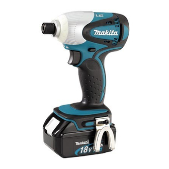
BTD140
Cordless Impact Driver
Battery
type
quantity
BL1830
2
=rpm
1
Assorted Phillips bits
Assorted socket bits
Bit piece
Charger
Offered to
USA, Canada
Mexico, Panama
DC18SC
All countries except
those listed above
18
3.0
Li-ion
220
6.35mm (1/4") Hex
M4 - M8 (5/32 - 5/16")
M5 - M14 (3/16 - 9/16")
M5 - M12 (3/16 - 15/32")
22 - 125mm (7/8 - 4-7/8")
0 - 3,200
0 - 2,300
145 (1,280)
Yes
Yes
Yes
1.5 (3.3)
PRODUCT
P 1 / 9
Dimensions: mm (")
Length (L)
146 (5-3/4)
Width (W)
79 (3-1/8)
Height (H)
235 (9-1/4)
Advertisement
Table of Contents

Related Manuals for Makita BTD140


Summary of Contents for Makita BTD140
- Page 1 Description Cordless Impact Driver ONCEPT AND MAIN APPLICATIONS Model BTD140 has been developed as the 18V version of the current 14.4V Cordless impact driver Model BTD130F. 18V battery delivers powerful 220W maximum output, yet still extra-lightweight design has been achieved by using 4-pole motor and Lithium-ion battery as power unit.
- Page 2 Socket 30-78 134848-9 Socket 32-50 Fixing Hammer case [2] LUBRICATION Apply Makita grease N. No.2 to the following portions designated with the black triangle to protect parts and product from unusual abrasion. Part description Where to lubricate Item No. Hammer case complete Inside surface where twenty-four 3.5 Steel balls are installed...
- Page 3 P 3 / 9 epair [3] DISASSEMBLY/ASSEMBLY [3] -1. Disassembling/Assembling Hammering Mechanism Fig. 2 DISASSEMBLING 1) Remove Belt clip by unscrewing Screw M4x12. Bumper Hammer case Rear cover After removing Bumper and Hammer case cover by hand, then remove Rear cover by unscrewing two PT3x16 Tapping screws.
- Page 4 P 4 / 9 epair [3] -1. Disassembling/Assembling Hammering Mechanism (cont.) 6) Install Center Attachment (No.1R346) on Gear Extractor, large (1R045). Fig. 5 (Fig. 5) 7) Set the Gear Extractor on the Hammering mechanism (= assembled unit of 1R045 Hammer, Spindle, Spur gears, Steel balls, etc.) as illustrated in Fig. 6. Then turn the handle of the Gear Extractor clockwise to lower Hammer to 1R346 the full.
- Page 5 P 5 / 9 epair [3] -1. Disassembling/Assembling Hammering Mechanism (cont.) ASSEMBLING Do the reverse of assembling steps. Note: 1) Assemble by piling component parts on Bearing box as illustrated in Fig. 10. 2) Make sure that twenty-six 3.5 Steel balls are in place inside Hammer. 3) Do not forget to install O ring 40 when assembling Internal gear 51 to Bearing box.
- Page 6 P 6 / 9 epair [3] -2. Disassembling/Assembling Bit Holder Section DISASSEMBLING 1) Put Anvil on Pipe 30 (No.1R232). (Fig. 13) 2) Put your thumb on the top of Sleeve so that Compression spring 13 does not pop out of Sleeve. (Fig.
- Page 7 P 7/ 9 epair [3] -3. Disassembling/Assembling Motor Section (cont.) ASSEMBLING Do the reverse of disassembling steps. Important: 1) Yoke unit is not reversible when assembled to Armature. Be sure to assemble so that the notch in Yoke unit is positioned on the drive-end of Armature.
- Page 8 P 8/ 9 ircuit diagram Color index of lead wires' sheath Brush holder Black Light circuit complete Orange Blue Switch Terminal Connector iring diagram [1] Lead Wire of Carbon Brush As illustrated to left in Fig. 20, put each Carbon brush into Brush holder so that its lead wire is placed outside.
- Page 9 P 9/ 9 iring diagram [2] Wiring in Housing Fig. 21 [2] -1. Lead Wires of LED As illustrated below, fix the two lead wires (red and black) of LED with lead wire holders, and route them between the pin and the boss. lead wire holder lead wire holder Fit the corner of LED in this...
Need help?
Do you have a question about the BTD140 and is the answer not in the manual?
Questions and answers