Table of Contents
Advertisement
Quick Links
Inhalt
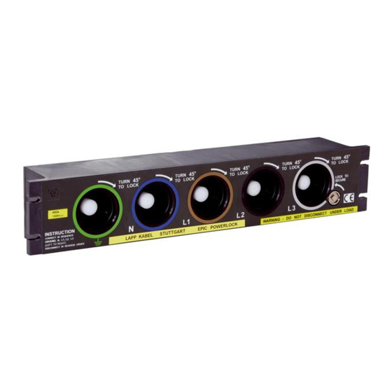
1 Colour Coding .......................................................................................................................... 2
2 Un-packing & content .............................................................................................................. 2
3 Mounting at the control cabinet/ buliding .............................................................................. 2
3.1 Mechanical mounting ....................................................................................................... 2
3.2 Power installation ............................................................................................................. 3
3.3 Connector for remote sensing ......................................................................................... 3
4 Installation and usage.............................................................................................................. 4
4.1 Warnings ........................................................................................................................... 4
4.2 Connection with cable connectors ................................................................................... 4
5 Technical data ......................................................................................................................... 5
6 Maintenance & disposal .......................................................................................................... 5
7 Appendix - Mounting of the micro switch connector ............................................................. 6
POWERLOCK BOX
User manual
Advertisement
Table of Contents

Subscribe to Our Youtube Channel
Summary of Contents for LAPP POWERLOCK BOX
- Page 1 POWERLOCK BOX User manual Inhalt 1 Colour Coding .......................... 2 2 Un-packing & content ......................2 3 Mounting at the control cabinet/ buliding ................2 3.1 Mechanical mounting ....................... 2 3.2 Power installation ......................3 3.3 Connector for remote sensing ..................3 4 Installation and usage......................
- Page 2 Before unpacking, make sure that the packaging is undamaged. Before unpacking, the part number of the POWERLOCK BOX should be checked against your order. Also check that the current rating label on the unit matches your requirements. The carton should contain the following: ...
- Page 3 27.5 Nm min. to 31.4 Nm max. It is recommended that insulated spanners are used when making these connections. 3.3 Connector for remote sensing A 2-pole Trident connector is at the back of the POWERLOCK BOX to enable remote sensing.
- Page 4 Ensure that the current rating of the cables and connectors being used are suitable for the current rating of the POWERLOCK BOX and connected supply. Do not connect / disconnect under load! 4.2 Connection with cable connectors...
- Page 5 Mounting and maintenance should only be performed by qualified staff. Periodic greasing of the O-Ring seals on the connector ports is recommended. The POWERLOCK BOX should regularly be inspected for damage, including a visual in- spection of the source contacts.
- Page 6 8. Screw the endbell to the connector and hand tighten 9. Select and fit a suitable clamp bar for your wire/cable and tighten screws. U.I. Lapp GmbH D-70565 Stuttgart/Germany www.lappgroup.com A Company of the Lapp Group...
Need help?
Do you have a question about the POWERLOCK BOX and is the answer not in the manual?
Questions and answers