
Related Manuals for Kyoritsu Electrical Instruments Works, Ltd. KEW 6010B


Summary of Contents for Kyoritsu Electrical Instruments Works, Ltd. KEW 6010B
- Page 1 INSTRUCTION MANUAL MULTI-FUNCTION TESTER KEW 6010B KYORITSU ELECTRICAL INSTRUMENTS WORKS, LTD.
-
Page 2: Table Of Contents
8. 2 What does the RCD test really do? ........21 8. 3 What is Uc? ................22 8. 4 Uc Testing ................23 8. 5 Operation of KEW 6010B RCD testing ......... 23 8. 6 RCD testing ................. 23 8. 6. 1 "NO TRIP" and "TRIP" test ........... 23 8.... -
Page 3: 1.Safety Warning
1. SAFETY WARNING Electricity is dangerous and can cause injury and death. To avoid possible electric shock, personal injury or damage of instrument, always treat it with the greatest of respect and care. If you are not quite sure how to proceed, stop and take advice from a qualified person. - Page 4 returned to your distributor for attention. 14. Do not operate the function switch while the instrument is connected to a circuit. If, for example, the instrument has just completed a continuity test and an insulation test is to follow, disconnect the test leads from the circuit before moving the function switch.
- Page 5 Measurement categories (Over-voltage categories) To ensure safe operation of measuring instruments, IEC 61010 establishes safety standards for various electrical environments, categorized as O to CAT IV, and called measurement categories. Higher-numbered categories correspond to electrical environments with greater momentary energy, so a measuring instrument designed for CAT III environments can endure greater momentary energy than one designed for CAT II.
-
Page 6: 2.Instrument Layout
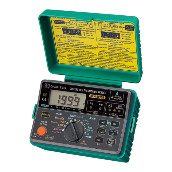
2. INSTRUMENT LAYOUT Fig. 1 I Δ n SELECT SWITCH: Available FUNCTION NO.6, 7, 8, 9, 10 (MEMORY SELECT SWITCH) 0°/180°SELECT SWITCH: Available FUNCTION NO.4, 6, 7, 8, 9 (MEMORY RECALL SWITCH) UL VALUE SELECT SWITCH: Available FUNCTION NO.6, 7, 8, 9 (ENTER SWITCH) AUTO NULL SWITCH: Available FUNCTION NO.1 (MEMORY CLEAR SWITCH) -
Page 7: 3.Features
3. FEATURES KEW 6010B Multi-Function tester performs six functions in one instrument. 1. Continuity tester 2. Insulation resistance tester (500V/1000V) 3. Loop impedance tester 4. RCD tester 5. Uc tester 6. Mains voltage warning when operating the Loop, RCD and Uc mode. - Page 8 Auto discharge Electric charges stored in capacitive circuits are discharged automatically after testing by releasing the test button. Loop impedance, RCD and Uc testing functions have the following features:- Voltage level S u p p l y v o l t a g e i s d i s p l a y e d w h e n t h e instrument is connected to the supply until the test button is pressed.
-
Page 9: 4.Specification
4. SPECIFICATION Measurement Specification Continuity Range Accuracy Open Circuit Voltage (DC) Short Circuit Current Up to 2Ω ± (3%rdg + 4dgt) Greater than 20/200Ω Greater than 6 V 200mA@2Ω Auto - Ranging Over 2Ω ± (3%rdg + 3dgt) Insulation Resistance Function Open Circuit Voltage (DC) Rated Current Range Accuracy... - Page 10 To prevent wrong connection of test leads and to maintain safety, the dedicated terminals used for continuity and insulation tests are automatically covered when using the terminals for Loop impedance, RCD and Uc tests. Typical Number of Tests (central tendency for supply voltage up to 8V at R6P) Continuity Ranges : Approx.
- Page 11 Instrument dimensions:- 175 X 115 X 86mm Instrument weight:- 840g including batteries. Reference conditions Specifications are based on the following conditions except where otherwise stated:- 1.Ambient temperature: 23± 5℃ 2.Relative humidity 45% to 75% 3.Position: horizontal 4.AC power source 230V, 50Hz 5....
-
Page 12: 5.Continuity (Resistance) Tests
This measurement should not include the resistance of any test leads used. The resistance of the test leads needs to be subtracted from any continuity measurement. KEW 6010B is provided with a continuity null feature which allows automatic compensation for any test lead resistance. - Page 13 4. Release the test button. Press the test button and ensure the display reads zero before proceeding. While using the Continuity null function, " " appears on the LCD. The null value will be stored even if power off the instrument. The memorized null value can be cancelled by disconnecting the test leads and pushing the AUTO NULL SWITCH with the test button pressed or locked.
-
Page 14: 6.Insulation Tests
This charge must be removed from the system at the end of the test, a function which is automatically performed by KEW 6010B. If an alternating voltage is applied between the conductors, the system continuously charges and discharges as the applied voltage alternates, so that there is a continuous alternating leakage current flowing to the system. -
Page 15: 6. 1. 3 Conduction Current
6. 1. 3 Conduction Current Since the insulation resistance is not infinite, a small leakage current flows through the insulation between conductors. Since Ohm's Law applies, the leakage current can be calculated from applied voltage (V) Leakage current (μA) = insulation resistance (MΩ) Fig 5 6.... -
Page 16: 6. 2 Damage To Voltage Sensitive Equipment
The system is charged to the full test voltage, and will be dangerous if left with this charge. KEW 6010B provides an automatic path for discharging current as soon as the test button is released to ensure that the circuit under test is safely discharged. -
Page 17: 6. 3 Preparation For Measurement
6. 4 Insulation resistance measurement KEW 6010B has a selectable, double test voltage of 500V and 1000V DC. 1. Select the insulation resistance setting by rotating the function switch to the required test voltage - "500V" or "1000V" as indicated under the "insulation"... - Page 18 3. If the mains warning LED lights and/or the buzzer sounds DO NOT PRESS THE TEST BUTTON but disconnect the instrument from the circuit. Make the circuit dead before proceeding. Fig 8 4. Press the test button when the display will show the insulation resistance of the circuit or the appliance to which the instrument is connected.
-
Page 19: 7. Loop Impedance Tests
○ Even though the test current in the 2000 ohm range (15mA test current) is low some RCD's may trip due to sensitivity or where there may already be additional leakage in the circuit being tested. ○ The Loop impedance in a TN system is small and therefore it is not recommended to test in the 2000 ohm range. -
Page 20: 7. 3 Automatic Over-Temperature Cut-Out
● Impedance of the power transformer secondary winding. ● Impedance of the phase conductor resistance from the power transformer to the location of the fault. ● Impedance of the protective conductor from the fault location to the local earth system. ●... -
Page 21: 7. 4 The Loop Impedance Test
1.Power on the instrument. 2.Set the function switch to Loop 20Ω range. 3. If testing sockets, connect the plug lead to the KEW 6010B and push the moulded plug into the socket to be tested (see Fig 11). 4.Check the wiring LEDs are lit (see above). -
Page 22: 7. 5 Loop Impedance At 3 Phase Equipment
WARNING Do not connect phase to phase as this instrument is rated at 230V. 7.5 Loop impedance at 3 phase equipment Use the same procedure as in 7.4 above ensuring that only one phase is connected at a time i.e.: First Test: red lead to phase 1, black lead to neutral, green lead to earth. -
Page 23: 8.Rcd/Uc Tests
RED (L) GREEN (PE) BLACK (N) Fig 12 8. RCD/Uc TESTS DISCONNECT THE INSTRUMENT FROM THE CIRCUIT UNDER TEST BEFORE OPERATING THE FUNCTION SWITCH TO SELECT THE RCD OR UC TEST RANGE SELECT "RCD" OR "UC" 8.1 Purpose of the RCD test The RCD must be tested to ensure that operation takes place quickly enough to ensure that there is unlikely to be serious danger to a person experiencing an electric shock from the system. -
Page 24: 8. 3 What Is Uc
When with the Uc Test letting flow IΔN to the RCD, the Uc is calculated. Fig 13 Uc voltage is calculated based on the Rated Residual Current (IΔN) with the impedance measured. KEW 6010B has two Uc functions as follow: ●Monitors Uc value At "Uc" range, Uc value (0-100V) can be displayed. -
Page 25: 8. 4 Uc Testing
6.If the LEDs are correctly lit, press the test button. 8.5 Operation of KEW 6010B RCD testing The RCD range of KEW 6010B has been improved comparing with our Model 6010A. Therefore, may differ a little bit from Model 6010A. ● Distortion factor of test current ... - Page 26 3. Set the phase angle to indicate 0°in the display. (The initial value is 0°) 4.Set the UL value 50V or 25V. (The initial value is 50V) 5. Connect the instrument to the RCD to be tested either via a suitable socket outlet (see Fig 11) or using the Model 7133B (OMA DIEC) test lead set (see Fig 12).
-
Page 27: 8. 6. 2 "Fast Trip" Test
8.6.4 Testing Auto Ramp " " KEW 6010B has a facility to test the current that are tripped the RCD under test. Proceed as follows: 1. Set the function switch to "Auto Ramp" and the IΔN select switch to the rated residual operating current of the RCD under test. -
Page 28: 8. 7 Testing Time Delayed Rcd's
OPERATION OF THIS TEST. Note: ● KEW 6010B calculates the Uc voltage with the impedance measured, and if the calculated Uc voltage exceeds UL, KEW 6010B indicates the warning "UcH v" on the LCD and stops the measurement. If the value is less than UL, the unit proceeds with the measurement of a RCD. -
Page 29: 9.Store / Recall A Measured Result
9. STORE / RECALL A MEASURED RESULT Measured result at each function can be stored in the memory of the instrument. (MAX : 300) When KEW 6010B is in MEMORY MODE, " " is being displayed on the LCD. 9.1 How to store the data Store the result according to following sequence. -
Page 30: 9. 2 Recall The Stored Data
9.2 Recall the stored data Stored data can be displayed on LCD according to following sequence. (1) Press to enter into MEMORY MODE (" " appears on LCD). NORMAL MODE MEMORY MODE (2) Press to recall. Undo (3) Press and select ... -
Page 31: 9. 3 Delete The Stored Data
9.3 Delete the stored data Stored data can be deleted according to following sequence. (1) Press to enter into MEMORY MODE (" " appears on LCD). NORMAL MODE MEMORY MODE (2) Press to recall. Undo (3) Press and select Data No. ("ALL"... -
Page 32: 9. 4 Transfer The Stored Data To Pc
(1) Firmly insert the D-SUB 9Pin female connector of Model 8212 into the socket (D-SUB 9Pin male) of PC. (2) Insert Model 8212 into KEW 6010B as shown in Fig 14. Test Leads shall be removed from KEW 6010B at this time. -
Page 33: 10.Battery / Fuse Replacement
10. BATTERY / FUSE REPLACEMENT WARNING NEVR OPEN THE BATTERY COVER WHILE MAKING MEASUREMENT. TO AVOID POSSIBLE ELECTRICAL SHOCK, DISCONNECT THE TEST LEAD AND POWER OFF THE INSTRUMENT BEFORE OPENING THE BATTERY COVER FOR BATTERY OR FUSE REPLACEMENT. 10.1 Battery replacement When the display shows the low battery indication "... -
Page 34: 11.General
11. GENERAL The test button can be locked down for ease of use by pressing it and turning clockwise. Do not forget to release test button by turning it counterclockwise before disconnecting the instrument from the test points. Failure to do so may leave the tested circuit in a charged condition when carrying out insulation test. -
Page 35: 13.Case, Strap And Shoulder-Pad Assembly
13. CASE, STRAP AND SHOULDER-PAD ASSEMBLY Correct assembly is shown in Fig 16. By hanging the instrument round the neck, both hands will be left free for testing. ① Pass the strap DOWN through the first case lug,under the case and UP through the other lug. - Page 36 DISTRIBUTOR Kyoritsu reserves the rights to change specifications or designs described in this manual without notice and without obligations. 9-18 92-1733D...
Need help?
Do you have a question about the KEW 6010B and is the answer not in the manual?
Questions and answers