Table of Contents
Advertisement
Quick Links
Programming a receiver with ON / OFF functionality
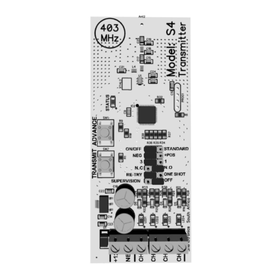
1. Select the ON OFF function jumper on both the receiver you are programming and the S4.
Note: Make sure the receiver is defaulted & remove any wires from the S4 channel inputs.
2. Press the ADVANCE button on the S4. Channel 1 LED will switch on.
3. Press the LEARN button on the receiver. The receiver beeps once.
4. Press the TRANSMIT button on the S4. This activates the ON signal. The LED will flash 5 times.
The receiver will beep a few times acknowledging that it is learning the signal.
5. Press the LEARN button on the Receiver again. The receiver beeps twice.
6. Press the ADVANCE Button on the S4. The LED will flash continuously.
7. Press the TRANSMIT button to learn in the OFF signal on to the receiver. The receiver will beep a
few times acknowledging that it is learning the signal.
9. Follow steps 2 to 7 for each Channel following or just keep pressing the ADVANCE button until
the unit steps past Channel 4 and the LED's start to running to indicate the unit is in standby.
10. Test that the ON /OFF function is working correctly by triggering the channel inputs with a wire
connected to either POSITIVE or NEGATIVE
ON / OFF functionality explained
Once the ON/OFF jumper is connected, the transmitter will transmit a signal encoded to switch a receivers relay contact
either ON or OFF depending on the transmitters trigger input condition. The function will only work on ON / OFF
(enabled receiver units). This functionality ensures the unit does not get out of sequence with the receiver as with
normal latching/unlatching functions. If you are using a different 12V power-source to that of the transmitter, then it is
recommended to common up on the Ground / Negative so that all the devices have a common negative reference.
NEG & POS jumper setting explained
By enabling the NEG jumper the unit will trigger when a Negative input or ground reference. The +POS jumper enables
the unit to trigger from a Positive voltage reference input.
1 & 3 jumper setting explained
By enabling the 1 jumper the unit will trigger one RF signal when its input is triggered.
Jumper 3 will enable the unit to trigger 3 x RF signals every time the input is triggered. We recommend setting the unit
to 3 for all alarm applications.
N.C & N.O jumper setting explained
By enabling the N.C jumper the unit will trigger from Normally Closed inputs. All un-used inputs must be bridged out
when using the N.C setting. N.O will enable the unit to trigger from Normally Open inputs.
RE-TRY jumper setting explained
By enabling the RE-TRY jumper the unit will re-transmit out a signal every 10 minutes. This ensures the system
works reliably and does not miss any ON or OFF signals. This function will only work when the ON/OFF function
jumper is enabled.
Supervision functionality explained
The SUPERVISION Jumper enables the unit to transmit out a system alive signal every 60 minutes.
This function will only be compatible to receivers that have SUPERVISION enabled firmware.
Please refer to the relevant receivers installation manual for a more info.
Compatible receivers
Please follow the relevant Receivers Installation instructions to programming the unit to a receiver.
The S4 is compatible to the following Receiver models:
Model: RX1-150; Model: RX2-150; Model: RX3-150; Model: RX1-500; Model: RX4-500; Model: MB4000
Warranty
This product is sold subject to our standard warranty conditions and is warrantied against defects in workmanship
for a period of two years.
Customer Support line: +2711 462 5101 E-mail: technical@sherlotronics.co.za
English
Installation Instructions - For Service Persons Only
Model: S4
Model No: S4
4 Channel Stand-alone Transmitter
High Level
+12V
NEG
COM
Low Level
Technical Specifications:
Model:
Encryption type:
Transmission frequency:
Transmission method:
Modulation
Transmission range:
Voltage range:
Standby current consumption:
Current consumption on TX:
Operating Temperature:
Dimension (lxbxh)
Gross weight:
Features:
Code-Hopping Encryption
4 Independent Inputs
Positive or Negative triggering
Normally Open / Closed
Weather-proof ABS housing
Frequency stability controlled +/- 75KHz
Order Codes:
4 Channel Stand-alone Transmitter
For more info visit our web site: www.sherlotronics.com
S4
Code hopping
403MHz (Local) 433MHz (Export)
OOK
AM
1500m "Line of sight"
10V to 16VDC
< 20mA
< 110mA
-3°C to 49°C
145 x 66 x 40mm
135g
Approvals:
This product is approved for use in Residential, commercial and
Light Industrial Environment and Complies with the essential
protection requirements of the R&TTE Directive 1999/EC on the
approximation of the laws of the Member states relating to
electromagnetic compatibility and radio spectrum.
Certifications:
ETSI EN300 220-V2.4.1
ETSI EN301-489-3 V1.4.1
ETSI EN301-489-1 V1.9.2
IEC 60950-1:2005 + A1:2009
III
S4
TA-2017/1572
APPROVED
S4
Advertisement
Table of Contents

Related Manuals for Sherlo Tronics S4


Summary of Contents for Sherlo Tronics S4
- Page 1 3. Press the LEARN button on the receiver. The receiver beeps once. 4. Press the TRANSMIT button on the S4. This activates the ON signal. The LED will flash 5 times. The receiver will beep a few times acknowledging that it is learning the signal.
- Page 2 Opening the unit Wiring diagram Remove the aerial and make sure the screw on the bottom side is removed. Carefully lift the lid up from the back end and unclip the top. Connecting a motion beam Connecting a siren alarm panel output Screw hole AUX - AUX +...
Need help?
Do you have a question about the S4 and is the answer not in the manual?
Questions and answers