Table of Contents
Advertisement
Advertisement
Chapters
Table of Contents

Summary of Contents for Spacelabs 91369
-
Page 1: Service Manual
91369 Service Manual 070-1156-00 Rev. F... - Page 2 All rights reserved. Contents of this publication may not be reproduced in any form without the written permission of Spacelabs Medical. Products of Spacelabs Medical are covered by U.S. and foreign patents and/or pending patents. Printed in U.S.A. Specifications and price change privileges are reserved.
-
Page 3: Table Of Contents
Diagnostic Menus ................5-7 91369 Service Manual... - Page 4 Separation Distances ............... A-3 Appendix B — Symbols 91369 Service Manual...
-
Page 5: Introduction
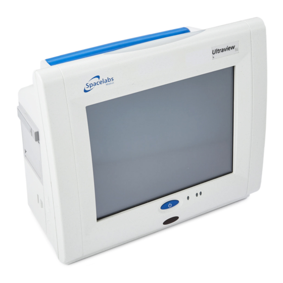
Failure to observe notifications may result in unexpected outcomes. The 91369 monitor is a lightweight, portable monitor designed for use as a compact bedside monitor or as a battery-operated transport monitor. The monitor features a five-wire, resistive touchscreen and can be operated on either AC mains or battery power. - Page 6 Introduction Figure 1-1: 91369 monitor Figure 1-2: 91369-Y Neonatal intensive care unit (NICU) monitor 91369 Service Manual...
-
Page 7: Physical Dimensions
0° to 50° C Humidity (operating) 10% to 95% relative humidity, non-condensing Regulatory Approvals ® ® 0123 CSA certified. Meets IEC60601-1, UL60601-1, and CSA C22.2 No. 601.1 for electrical safety. CE marked in accordance with the Medical Device Directive 93/42/EEC. 91369 Service Manual... -
Page 8: Monitor Options
Introduction Monitor Options The following options are available: Table 1: 91369 Monitor Options Option Definition Perioperative Dual-channel internal recorder (Polish,Czech, Portuguese language support only) Vital Signs Calculations Drug Dose Calculations ® Data Shuttle Patient Data Logger (PDL) Dual-channel internal recorder (no Polish language support) -
Page 9: Setup
Configuring the Monitor ..............13 Unpacking the Monitor The 91369 monitor, one or two batteries, external AC power supply, and any optional accessories are all packaged and shipped in a single box. Keep at least one shipping box and its packing materials for re- shipping, if the monitor should ever require factory service. -
Page 10: Assembling The Monitor
This inventory must include serial numbers, model numbers, and all options and cables received. Carefully inspect these items for shipping damage. If any damage is evident, immediately notify the freight company and Spacelabs Healthcare. Assembling the Monitor... - Page 11 Replace a faulty battery with the same battery type. Installing/Replacing Batteries NiMH batteries are used in the monitor. Refer to Figure 2-2 to install one or two batteries. Figure 2-2: Monitor battery installation 91369 Service Manual...
-
Page 12: Connections
Refer to Figure 2-3 for available connections on the monitor’s rear panel. Refer to Figure 2-4 for available connections on the monitor’s side panel. Rear Panel Equipotential ground post External power supply input SDLC port Alarm relay output Video output Serial port ³ » ¿ ´ ² Figure 2-3: Rear panel connections 91369 Service Manual... - Page 13 Cable, Monitor to Module Housing, 3.05 m (10 feet) 012-0532-10 Caution: For continued electromagnetic interference (EMI) radiation compliance, use only cables that have been tested and approved by Spacelabs Healthcare. Refer to Table 2 on page 6-3 for all cable part numbers. 91369 Service Manual...
-
Page 14: Side Panel
10/100BaseT network connection ¶ º Figure 2-4: Side panel connections Note: The USB ports are to be used for Spacelabs-approved devices only (Symbol/Metrologic barcode scanner and Microsoft USB keyboard/mouse devices). Table 2: Side Panel Cables Side Panel Description Part Number Connection Cable, Ethernet, 10/100BaseT, 0.94 m (3 feet) -
Page 15: Cabling
• SDLC Cable — 12.2 m (40 feet) maximum (total length from the monitor to the last device on the bus). For longer SDLC cable runs, contact a Spacelabs Healthcare Field Service Engineer. • Video Cable — 30.5 m (100 feet) maximum (total length from the monitor to the last display). -
Page 16: Sdlc Bus Termination
Note: Flexports require a powered Flexport cable (P/N 012-0555-00) when used with the 90491/90499 module housing or 91369 monitor. SDLC data is only passed along to the external device(s) when the terminator switch (SW2) is in the position. Alarm Relay Alarm output signals are available at the Nurse Alert ( ) connector instantaneously when an alarm occurs. - Page 17 EXCEEDED: • Current = 250 ma • Voltage = 28 V AC/DC +5 V common Relay maximum ratings: 28 V AC/DC 0.25 A relay ALMON +12 V 140 mA Figure 2-6: Alarm 0 (high priority) relay schematic 91369 Service Manual...
- Page 18 +12 V 140 mA Figure 2-7: Alarm 1 (medium priority) relay schematic +5 V common Relay maximum ratings: 28 V AC/DC 0.25 A relay ALMON +12 V 140 mA Figure 2-8: Alarm 2 (low priority) relay schematic 91369 Service Manual 2-10...
-
Page 19: Network Installation
The monitor must be properly configured for LAN access before you operate the monitor. If you fail to correctly configure the monitor, you may interrupt other units also using the LAN. Note: Detailed installation instructions for the physical Ethernet LAN are beyond the scope of this document. 91369 Service Manual 2-11... -
Page 20: Power-On Test
Setup To connect a monitor onto an existing Spacelabs Healthcare Ethernet LAN, complete the following steps: 1 Install the monitor on a suitable table or shelf, ensuring that the air flow to the side air intake vents is unobstructed, or use a Spacelabs Healthcare mounting option. -
Page 21: Configuring The Monitor
SAVE is selected. The description of each tab indicates when that change takes effect (for example, immediately or after a monitor reset occurs). To edit text within a tab: 1 Select an item from the list. -OR- 91369 Service Manual 2-13... - Page 22 Subnet Mask — Enables you to identify which parts of the IP address are to be used for TCP/IP subnet determination. The TCP/IP network’s subnet mask is not related to the Spacelabs Healthcare network’s subnet name. The standard and factory-default subnet mask is 255.255.255.0. Either a subnet mask must be specified, or DHCP networking must be enabled.
- Page 23 Enter a valid IP Address when your network is using static IP addresses. -OR- Enter a valid Secondary DNS hostname when your network is using DHCP for network configuration. Changes made to the Secondary Display settings take effect after the changes have been saved. 91369 Service Manual 2-15...
- Page 24 The Monitor ID is the numeric ID assigned to a monitor. Each device on the network must have a unique Monitor ID. This can be any number from 1 to 1023, depending on the Network Size selected. 91369 Service Manual 2-16...
- Page 25 When entering a monitor name or ID, do not use a space between characters. DECNET/IP You can configure the monitor to operate using either Spacelabs DECNET or TCP/IP network protocols. If you are communicating with 903xx Spacelabs Healthcare monitors, you must select DECNET.
- Page 26 A local (SDLC) printer can be either a bedside printer or network printer, depending on the printer name selected in this list. A local printer is configured as a network printer if the local monitor’s name is selected. Otherwise, a local printer functions as the bedside printer. 91369 Service Manual 2-18...
- Page 27 Figure 2-14 are not available for selection if the radio is not present. Caution: Do NOT power the radio ON until all network configuration has been completed. Powering the radio ON with the monitor set to the factory defaults could interfere with the wireless network. 91369 Service Manual 2-19...
- Page 28 The Wireless DHCP tab is similar in function to the DHCP key on the TCP/IP tab, but for wireless networks. When Wireless DHCP is selected, the monitor asks the wireless DHCP server for the following information: • WLAN IP Address • WLAN Subnet Mask • Gateway Address 91369 Service Manual 2-20...
- Page 29 If enabled, WLAN card communication through the wireless network depends on the interaction between the WLAN card SSID setting (refer to SSID (default = blank)) and its security settings (refer to Security Tab on page 2-24). 91369 Service Manual 2-21...
- Page 30 Table 6. The frequencies available in a particular country differ according to the regulations of that country. Consult your national and local regulations. Table 6: Region Codes Value Center Frequency Range Region Blank Disabled Europe (ETSI), except France 2412 to 2472 MHz and Spain 2412 to 2462 MHz North America 91369 Service Manual 2-22...
- Page 31 Allows the operator to specify the IP address of a wireless TCP/IP gateway (bridge or router) through which wireless communication to other devices should flow, when Wireless DHCP is not selected. The Gateway address on the WLAN tab is not related to the Gateway address on the TCP/IP tab. 91369 Service Manual 2-23...
- Page 32 Whenever Disabled is selected, the only other items displayed within the tab are the Authentication Mode key (disabled with OPEN selected) and the SAVE key. If Disabled is selected and saved, the SAVE key becomes unavailable. 91369 Service Manual 2-24...
- Page 33 AP: Open and Shared Key. Wireless networking is only available if the authentication modes of the AP and the WLAN card match. Setting Security Mode to Disabled disables this key, with OPEN selected. 91369 Service Manual 2-25...
- Page 34 When selecting a Data Rate, select the maximum data rate that the WLAN interface should use when sending unicast and multicast data packets. The WLAN interface uses a lower rate if reliable network communication cannot occur at the selected higher data rate. 91369 Service Manual 2-26...
- Page 35 Invalid Region Code — XXX (either <0 or > 99) (WLAN tab). Note: If the invalid IP address or subnet mask is related to use of the WLAN, monitors that are configured for radio/WLAN operation append “WLAN” to the start of the error messages describe below. 91369 Service Manual 2-27...
- Page 36 To set up Patient Data Logger: 1 Touch MONITOR SETUP. 2 Touch PRIVILEGED ACCESS. 3 Enter the biomed password (default is biomed). 4 Touch SERIAL PORTS. 5 Touch ASSIGNMENT. 6 Touch DATA LOGGER. 7 Touch PREVIOUS MENU. 91369 Service Manual 2-28...
-
Page 37: Monitor Calibration
2 Enter the new biomed password in the New Password field and enter the same password again in the Verify Password field using the on-screen keyboard. Note: If the biomed password is forgotten, contact your Spacelabs Healthcare Field Service Engineer. 91369 Service Manual 2-29... - Page 38 The UNITS OF MEASURE key provides access to the units of measurement that the monitor uses for input, display, and printing of values for pressure, height, and weight measurements. Each key’s label indicates the available selections. Reset the monitor after making changes in this menu. 91369 Service Manual 2-30...
- Page 39 ALARM LEVEL — The alarm relay can be activated for all alarms or for alarms at or above the selected priority only. Selections of HIGH, MEDIUM, and LOW are available. For example, selecting MEDIUM results in activation of the alarm relay for HIGH and MEDIUM priority alarms, but not for LOW priority alarms. 91369 Service Manual 2-31...
- Page 40 • Subnet access • Units of measurement Touching the RESET MONITOR key displays the Reset Monitor dialog box. Select Reset Monitor to proceed or Cancel Reset to cancel. 91369 Service Manual 2-32...
- Page 41 • FACTORY DEFAULTS — This key deselects all the period keys, resets their values to the ISO standard values, and disables the arrow keys. 91369 Service Manual 2-33...
- Page 42 Touch EDIT DRUG LIST to display the Drug List Selection Menu (Figure 2-19). Selecting any drug name from this list highlights that line. The drug list may be blank (if all the entries are blank) or display one or more blank lines. 91369 Service Manual 2-34...
- Page 43 Identifier (PI) String on page 2-39 for information on using the transfer feature. Figure 2-20: Edit Drug dialog box Refer to the Ultraview SL Operations Manual (P/N 070-1150-xx) located on CD-ROM P/N 084-1101-xx for additional information. 91369 Service Manual 2-35...
-
Page 44: System Information
While the monitor is connected to AC power, AC displays below the AC/DC heading and the current battery charge current and battery resistance values display, along with values for various powers and temperatures (actual data may differ from the example in Figure 2-22). 91369 Service Manual 2-36... - Page 45 Figure 2-23), and the current battery voltage and %full values display, along with values for various powers and temperatures (line voltage displays asterisks). Figure 2-23: Analog system information - monitor not connected to AC power 91369 Service Manual 2-37...
- Page 46 The list of available access points lists the MAC address, the channel (Ch.), and the signal strength (Str.) of all APs that match the displayed SSID value. An asterisk (*) to the left of an AP indicates that the WLAN card is currently associated with this AP. 91369 Service Manual 2-38...
- Page 47 Monitors also truncate the PI string so that it does not run into or behind the parameter key and to ensure that it does not exceed the 40-character limit. 91369 Service Manual 2-39...
- Page 48 To configure the strings on multiple monitors: 1 Define and save the PI string on one monitor using the Define Patient Identifier String dialog box. 2 Touch the TRANSFER key to display the Transfer Patient Identifier Configuration dialog box. 91369 Service Manual 2-40...
- Page 49 Note: The SELECT ALL IN SUBNET and DESELECT ALL keys are unavailable if no monitors that support the transfer protocol exist within the selected subnet. Selection or deselection only applies to the keys for 91xxx monitors. 91369 Service Manual 2-41...
- Page 50 Figure 2-28: Purge patient data confirmation window Touch CASE PURGE /QUERY to prompt the user with the Purge Data confirmation window when the user touches END CASE. Touch CASE PURGE /ALWAYS to purge all patient data when the user touches END CASE. 91369 Service Manual 2-42...
- Page 51 The RESET MONITOR key in the Biomed Level menu allows you to reset the monitor after changing settings for the following items (the monitor must be reset before the changes can take effect): • Monitor ID • Monitor Name • Subnet Name • IP configurations • Start Case/End Case options 91369 Service Manual 2-43...
- Page 52 Setup Touching the RESET MONITOR key displays the Reset Monitor dialog box. Select Reset Monitor to proceed or Cancel Reset to cancel. Figure 2-30: Privileged Access - Reset Monitor dialog box 91369 Service Manual 2-44...
-
Page 53: Theory
There may also be additional hardware devices present, such as a mouse, keyboard, and barcode scanner. The monitor may also be used in conjunction with other hardware components, such as: • 90491/90499 module housings • Flexport system interface • Gas analyzer • External display 91369 Service Manual... -
Page 54: Major System Components
Description Pinout 5-pin DIN RETURN Figure 2-3 Power input male +18 Input on page 2-4 Data + Data - +5 V 9-pin SDLC connector +12 V Figure 2-3 Clock + on page 2-4 Clock - -12 V 91369 Service Manual... - Page 55 DB9 female Serial I/O Figure 2-3 DSR (data set ready) on page 2-4 RTS (ready to send) CTS (clear to send) +5 V out Mouse, keyboard, Data - Figure 2-4 barcode scanner Data + on page 2-6 91369 Service Manual...
-
Page 56: External Controls
, Synchronous Data Link Control (SDLC) interface, is electrically compatible with the EIA-RS485 standard. The communications protocol is derived from the IBM SDLC specification and uses its Non-Switched Multipoint Half-Duplex configuration. This interface is compatible with all Spacelabs Healthcare modules, Flexport interfaces, gas analyzers, telemetry receivers, and printers. -
Page 57: Printed Circuit Board Assemblies (Pcbas)
It has four major subsystems (Figure 3-1): • Power Supply • Core Processor, including all 64-bit peripherals • PCI subsystem, including 32-bit peripherals • ISA subsystem, including 16-bit peripherals Core processor Power supply PCI subsystem ISA subsystem Figure 3-1: CPU PCBA setup 91369 Service Manual... -
Page 58: Power Supply Connector
POWER +15 V TURN-ON Figure 3-2: Power supply section Power Supply Connector Power is supplied to the monitor from an external DC power supply. Power arrives at the CPU PCBA via a single connector, P100, at 18 VDC. 91369 Service Manual... - Page 59 The circuit uses a single-ended flyback converter topology. This pre-regulator circuit is active at all times when the monitor is powered from the external power supply voltage. 91369 Service Manual...
- Page 60 However, during battery charging, the battery chargers override the CPU and force the fan on at a higher than normal speed. This allows the battery chargers to run at full output without overheating the unit. Note: The fan will not operate unless a battery is installed. 91369 Service Manual...
- Page 61 Common Flash Interface (CFI) is the communication method. Two banks of Flash memory (Intel Advanced+ BootBlock C3-family, 64 Mbit, ×16, 80 ns) are used on each PCBA, providing a total of 16 MB of Flash memory. 91369 Service Manual...
- Page 62 Media Independent Interface (MII). Data communication is in Nibble mode (4 TX_D lines and 4 RX_D lines). The RJ-45 connector contains LEDs indicating speed (yellow ON for 100 MHz, yellow OFF for 10 MHz) and link status (green flashing about once every five seconds for Link Active). 91369 Service Manual 3-10...
- Page 63 10BaseT and 100BaseT applications. SDLC Interface The SDLC bus is the communications interface to Spacelabs Healthcare modules, which supply patient data to the monitors. The SDLC interface runs at 1.892352 MHz. This is divided down to generate a 448 Hz sampling rate.
- Page 64 PCI bus. The PCMCIA controller is placed on the secondary PCI bus through the PC/PCI bridge. The USB keyboard and mouse are supported by a USB controller located within the Intel 82371, which is USB v1.1 compliant. 91369 Service Manual 3-12...
- Page 65 GPIO on the MPC8270. Software can take action, if desired, on the assertion of this pin (for example, PCMCIA shutdown). The PCMCIA controller has a direct interrupt line to the MPC8270 CPU through IRQ3. 91369 Service Manual 3-13...
- Page 66 Dallas Semiconductor DS1644 non-volatile timekeeping RAM. It is a highly integrated device, containing the following: • 32 K × 8 static RAM. • Lithium battery with a 10-year life. • Time-of-day clock with ±1 minute per month accuracy. 91369 Service Manual 3-14...
-
Page 67: Interconnect And Connector Pcbas
(Optional) Recorder • (Optional) Recorder CPU • SDLC (module) The Interconnect PCBA also provides a signal pass-through to the Connector PCBA, which contains: • Serial Port • Analog Video • External Alarm Relay Output • SDLC 91369 Service Manual 3-15... -
Page 68: Bezel Assembly
Power indicator PCBA Battery charger status LEDs AC mains LED Power ON/OFF switch Infrared receiver Direct cable connection to CPU PCBA J061 for battery status, mains connected, infrared, and power switch • 12.1-inch TFT color LCD display 91369 Service Manual 3-16... - Page 69 Elo Touchsystems E271-2210 compatible Direct cable connection to P341 on CPU PCBA • Embedded alarm light assembly Direct cable connection to P941 on CPU PCBA Three banks of LEDs: cyan, yellow and red. Figure 3-7: Bezel assembly 91369 Service Manual 3-17...
-
Page 70: Boot Sequence Overview
That program uses the key display task to redraw the new key state as feedback to the user. The Global Data System (GDS) is the patient database with parameter data from the modules. It contains current, general, trend, and waveform data. 91369 Service Manual 3-18... -
Page 71: Display
The pinout of the display connector (at the display) is provided in Table 2. The backlight is connected via a separate 3-pin connector Table 2: Display Connector Pinouts on CPU PCBA P161 Pin Number Symbol Description HSYNC Horizontal Sync VSYNC Vertical Sync Red Data LSB Red Data MSB 91369 Service Manual 3-19... - Page 72 Table 2: Display Connector Pinouts on CPU PCBA P161 (continued) Pin Number Symbol Description Green Data LSB Green Data MSB Blue Data LSB Blue Data MSB Settle the horizontal display ENAB position +5 V +5 V Horizontal display mode select Vertical display mode select 91369 Service Manual 3-20...
-
Page 73: Cpu Pcba Connectors
Theory Parameter Modules Any single-high Spacelabs Healthcare parameter module can be inserted into the module slot of the monitor. The module receives +5 VDC, +12 VDC, and -12 VDC power from the monitor and communicates with the monitor via an SDLC data bus. In the most general terms, the module initially downloads a program (“table code”) into the monitor over the SDLC bus. -
Page 74: Cpu Pcba Jumpers
SuperCap discharge Open Closed — Discharges SuperCap I/O PCBA Connectors Table 5: I/O PCBA Connectors Reference Connector Type Description Internal/External 9-pin D SDLC External RS-232 serial interface External DB15HD Video output External 14-pin D Alarm relay External 91369 Service Manual 3-22... -
Page 75: Interconnect Pcba Connectors
Table 6: Interconnect PCBA Connectors Reference Connector Type Description Internal/External 80-pin CPU PCBA Internal 30-pin RCU PCBA Internal 50-pin Recorder Internal SDLC INTFC to CPU Internal Misc. signals INTFC to CPU Internal Ethernet INTFC to CPU Internal 15-pin SDLC Internal 91369 Service Manual 3-23... -
Page 77: Overview
• All static-sensitive electronic components are packaged in static-shielding bags. Retain the bag for repackaging the component should you need to store it or return it to Spacelabs Healthcare for any reason. •... -
Page 78: Mechanical Inspection
UUT — Unit Under Test. Spacelabs Healthcare does not endorse standards to the exclusion of others. Therefore: BE SURE TO CHECK YOUR LOCAL REQUIREMENTS TO ENSURE YOUR EQUIPMENT SAFETY TESTS COMPLY WITH LOCAL STANDARDS. -
Page 79: Equipment Required
Chassis Leakage Current Tests 1 Plug the leakage analyzers into mains power. 2 Plug the equipment into the analyzer’s AC receptacle. 3 Verify that the leakage current from the chassis to ground is less than the values in Table 2. 91369 Service Manual... -
Page 80: Preventive Maintenance
Refer to the service manual of the specific module(s) you are using for patient lead leakage test instructions. Preventive Maintenance A Spacelabs Healthcare Field Service Engineer or qualified hospital biomedical technician should check the monitor and optional equipment for acceptable performance and electrical safety to ensure they operate according to current requirements. -
Page 81: Functional Tests
The power ON/OFF switch illuminates. The embedded alarm light LEDs illuminate briefly. Verify that all LEDs are functional. The Diagnostic menu displays. (If errors are noted during power ON, contact your Spacelabs Healthcare Field Service Engineer.) If batteries are installed, the fan begins operating within 60 seconds after turning ON the monitor. The fan will then turn OFF unless the internal temperature requires additional cooling by the fan. -
Page 82: Assembly/Disassembly Procedures
RECORD key and then touching one of the flashing parameter keys. Note: The printed waveform should be free from defects such as gaps, extra lines, etc. If not, notify a Spacelabs Healthcare Field Service Engineer for servicing, or replace the recorder (refer to Recorder on page 5-19). - Page 83 6 Insert the recorder assembly, ensuring that it fully engages the connector at the back of the recorder compartment. Press the release bar to open the recorder assembly and tighten the two phillips-head screws located at the rear of the recorder. 91369 Service Manual...
- Page 84 Maintenance Figure 4-1: Recorder assembly and CPU PCBA Release bar Recorder assembly Recorder CPU PCBA, installed 91369 Service Manual...
- Page 85 Figure 4-2: Optional recorder assembly Release bar Recorder assembly Recorder CPU PCBA, installed 2 If replacing the recorder CPU PCBA, loosen the thumbscrew and pull it forward until it is free of the connector. 91369 Service Manual...
- Page 86 3 Slip the paper roll spindle between the plastic arms, and close the front of the assembly so that the end of the paper roll protrudes out of the recorder assembly just below the release bar. 91369 Service Manual 4-10...
- Page 87 Five screws along the bottom of the bezel Four screws along the top of the bezel 2 With the monitor standing upright, gently move the top of the bezel and disconnect the flat cable running from the display to the CPU PCBA. 91369 Service Manual 4-11...
- Page 88 Maintenance Figure 4-5: Removal of the front bezel Front panel power/LEDs cable Video cable 91369 Service Manual 4-12...
- Page 89 Caution: The glass touchscreen may stick to the front of the display bracket. Do not allow it to fall off of the bracket during removal. 3 Remove the four screws securing the display to the brackets. 91369 Service Manual 4-13...
- Page 90 5 To remove the backlight inverter, remove both cable assemblies and the two screws attaching the inverter to the display bracket. 6 When replacing the backlight inverter, be sure to replace the mylar shield (Figure 4-8) between the PCBA and the chassis. 91369 Service Manual 4-14...
- Page 91 Maintenance Figure 4-8: Backlight inverter Backlight inverter Mylar shield 91369 Service Manual 4-15...
- Page 92 1 Remove the batteries, if present. 2 Remove the bezel (refer to Removing the Bezel Assembly on page 4-11). 3 Remove the nine screws that hold the CPU PCBA to the chassis (refer to Figure 4-10). 91369 Service Manual 4-16...
- Page 93 2 Remove the bezel (refer to Removing the Bezel Assembly on page 4-11). 3 Hold the PCMCIA card adapter in place and press the eject bar ( ). The radio card ( ) releases from adapter. Remove the card and detach the antennas. 91369 Service Manual 4-17...
- Page 94 3 Insert the radio card into the Compact Flash card adapter on the main CPU PCBA. When the card is fully seated in the Compact Flash card adapter, the card eject bar ( ) extends. Refer to Figure 4-13. 91369 Service Manual 4-18...
- Page 95 Apply the antenna’s adhesive pad to the tip of a thin-bladed knife or small flat screwdriver. Use the knife or screwdriver to guide the antenna to the correct installation point (refer to Figure 4-15). Ensure that the antenna cable is not stressed or kinked. Figure 4-14: Antenna placement 91369 Service Manual 4-19...
- Page 96 Maintenance 7 Press down firmly, and hold the adhesive pad in place while removing the screwdriver or knife. Figure 4-15: Antenna installation, using a knife blade as a guide 91369 Service Manual 4-20...
- Page 97 7 To lift the chassis out of the case, place your left hand through the battery door and your right hand into the module access opening. Work the assembly upward, allowing the top to move ahead of the bottom. 8 The chassis is now ready for further disassembly. 91369 Service Manual 4-21...
- Page 98 Figure 4-17: Replacing the fan/battery contact assembly and Interconnect PCBA 3 Pry up the center retainer on the battery contact assembly (near the battery ejection springs). This should free the fan/battery contact assembly. 4 Remove the screw between the chassis and the Interconnect PCBA. 91369 Service Manual 4-22...
- Page 99 Figure 4-18: Module door Replacing the Embedded Nurse Alert Assembly 1 Remove the front bezel carefully. 2 Slide out the embedded nurse alert LED assembly. 3 Reverse the procedure to install the replacement. 91369 Service Manual 4-23...
-
Page 100: Cleaning
Never use solvents, acetone, abrasive cleaning agents, or abrasive cleaning pads. • Use only approved cleaning agents including 70% alcohol, soap and water, green soap, or 10% bleach solution. Note: Avoid directly spraying liquids into the recorder openings. 91369 Service Manual 4-24... -
Page 101: Overview
• All static-sensitive electronic components are packaged in static-shielding bags. Retain the bag should you need to repackage the component for storage or need to return it to Spacelabs for any reason. 91369 Service Manual... -
Page 102: System Startup
Error window System Startup window The normal countdown This window displays basic system configuration appears here. and booting status during the boot process. The Boot menu and Diagnostics menus also display here. Figure 5-1: System Startup window 91369 Service Manual... -
Page 103: Boot Menu
Keyboard or terminal — Press CNTL+D (the terminal’s serial port should be set to 9600 baud, no parity, 8 data bits, and one stop bit). Figure 5-2: Finger placement to initiate Boot menu using the touchscreen during the countdown 3 The Boot menu appears as shown in Figure 5-3. 91369 Service Manual... - Page 104 P — Allows this monitor to ping the host IP address [host inet (h)]. m — Requires a data key (Spacelabs field service engineers only). Displays the Memory menu (Figure 5- 7 on page 5-9), which allows the display, modification, copying, and filling of any memory or address space accessible to the CPU.
- Page 105 Troubleshooting b — Displays the Burn Flash menu, which allows new boot kernel or application software to be loaded over the network and burned into flash memory (Spacelabs field service engineers only). t — Recalibrates the touchscreen (monitor will reset).
-
Page 106: Power-On Diagnostics
To avoid false failures, do not use the touchscreen, mouse, or keyboard while the diagnostic tests are executing. Extended diagnostics failures are reported in the upper left corner of the System Startup screen. Refer to System Startup on page 5-2 for more information. 91369 Service Manual... -
Page 107: Diagnostic Menus
— Toggles Halt On Error Mode ON or OFF. When ON, any failure that occurs while tests are running in Loop Mode immediately stops testing. s — Shows system information, including details of address spaces and variables used in the system. R — Causes a cold boot reset just like turning the power OFF. 91369 Service Manual... - Page 108 P — Runs the power-ON diagnostic test. R — Ensures that the real-time clock is running. m — Requires a data key (Spacelabs field service engineers only) for some functions. Displays the Memory menu (Figure 5-7). v — Displays the Video menu.
- Page 109 — Performs the power-ON flash checksum. F — Performs a read/write test on the application area of flash memory, which overwrites the application software. Reload the software after the test. Requires a data key (Spacelabs Healthcare Field Service Engineers only).
-
Page 110: Error Log
From the Boot menu (refer to Boot Menu on page 5-3), touch E to access the Error Log Functions menu, then d to view the Error Log. 91369 Service Manual 5-10... -
Page 111: Diagnostics Failure Messages And Error Codes
FLASH ROM boot larger than Flash flash memory and retest. If failure persists, replace CPU PCBA. Reburn application software into 01030502 FLASH ROM app larger than Flash flash memory and retest. If failure persists, replace CPU PCBA. 91369 Service Manual 5-11... - Page 112 Replace CPU PCBA. 01030A06 Video could not detect blue video signal Replace CPU PCBA. Reboot and retest. If problem 01030C00 OS error while diagnosing KBD persists, replace CPU PCBA. 01030C01 Cannot access KBD device registers Replace CPU PCBA. 91369 Service Manual 5-12...
-
Page 113: System Troubleshooting
Replace CPU PCBA. Zero the NVRAM and reboot. Re-program all items in the Biomed, CSR, and Clinical 01030E02 NVRAM checksum error menus (Spacelabs field service engineers only). If problem persists, replace CPU PCBA. 01030E03 NVRAM read/write memory test failed Replace CPU PCBA. - Page 114 CPU PCBA, then the display screen. Caution: Do not attempt to troubleshoot the display backlight electronics. There are very HIGH AC voltages in this area. Only qualified Spacelabs Healthcare field service engineers should attempt to troubleshoot this section. Monitor Fails Power-ON Diagnostics Troubleshooting Method 1: Using the Touchscreen or Mouse 1 Display the Main Diagnostic menu.
- Page 115 2 Check the software versions of all installed modules, Flexport interfaces, and other SDLC equipment attached, verifying with Spacelabs Healthcare that there are no incompatibilities. 3 Inspect the Interconnect PCBA. If any connectors or parts appear damaged, replace the damaged assembly.
- Page 116 If the radio card connection appears to be good, the radio card, the PCMCIA card adapter, or CPU PCBA may need to be replaced. Note: Verify that the monitor’s on-screen display options includes the letter z; if the monitor does not, contact you Spacelabs Healthcare Field Service Representative. 91369 Service Manual 5-16...
-
Page 117: Alarm Relay
3 Inspect the I/O PCBA and the Interconnect PCBA if the problem persists. If any connectors or parts on either of these assemblies appear damaged, replace the damaged assembly. 4 If the problem persists, replace the CPU PCBA. 91369 Service Manual 5-17... -
Page 118: External Display
This gauge is useful in detecting bad batteries or other voltage problems in the system. After five minutes of operation on only one fully charged battery, if the battery fuel gauge reads 3/4 full or less, the battery may be faulty. 91369 Service Manual 5-18... -
Page 119: Battery Charger
LED will light ON and OFF with successive tests. If all diagnostics pass, the recorder will sign on to the SDLC link with the LED OFF. If a diagnostic error occurs, the LED is left ON or flashing. 91369 Service Manual 5-19... - Page 120 If the diagnostics detected a hardware failure in the recorder assembly, LED D2 will be continuously flashing ON and OFF. • If no failures were detected, LED D2 will be OFF. • During normal operation, D2 will be dimly lit (it is actually flashing very rapidly). 91369 Service Manual 5-20...
- Page 121 Stuck I/O bus bit 1 low Stuck I/O bus bit 2 low Stuck I/O bus bit 3 low Stuck I/O bus bit 4 low Stuck I/O bus bit 5 low Stuck I/O bus bit 6 low 91369 Service Manual 5-21...
- Page 122 Printer Tests - WRRDY inactive or -SYNC active after reset Printer Tests - Readback system wrong state after reset Printer Tests - Error active after reset Printer Tests - +BUSY not active after idle CMD Printer Tests - +BUSY not inactive after idle CMD 91369 Service Manual 5-22...
- Page 123 Watchdog timeout too long Stack error Printer error code - Printer did not like command sent Manual re-init seen Printer error during initialization Unload state error - Invalid state Already printing when another print command received 91369 Service Manual 5-23...
-
Page 125: Overview
• All static-sensitive electronic components are packaged in static-shielding bags. Retain the bag for repackaging the component should you need to store it or return it to Spacelabs Healthcare for any reason. Parts List... - Page 126 Retainer, Handle, 91369 343-0372-00 Handle, Enclosure, 91369 367-0833-00 Frame, Interconnect 426-0039-04 Frame, Contact, 91369 426-0041-01 Enclosure, Rear, 91369 437-5045-00 Plug, Hole, SDLC Port, 91369 134-0044-01 Latch, Battery 105-0038-01 Door, Battery 202-0228-00 Spring, Battery Door 214-0328-00 Pin, Hinge, Battery Door 214-0318-00...
- Page 127 Cable, Assembly, Ethernet, 10/100BaseT, 12 feet (3.7 m), PVC 175-0951-02 Cable, Assembly, Ethernet, 10/100BaseT, 20 feet (6.1 m), PVC 175-0951-03 Field-Replaceable Mounting Hardware Parts Table 3: Mounting Hardware Replaceable Parts Description Part Number Bed Rail Mount, 91369 016-0369-00 Power Supply Mount, Universal 016-0732-00 91369 Service Manual...
-
Page 128: Assembly Drawings And Schematics
2 (52 sheets) Schematics, PCBA, CPU 676-0684-06 3 (53 sheets) Schematics, PCBA, I/O 676-0705-00 4 (3 sheets) Schematics, PCBA, Interconnect 676-0148-02 5 (3 sheets) Schematics, PCBA, CPU, Recorder 676-0012-00 6 (4 sheets) System Block Diagram 7 (1 sheet) 91369 Service Manual... -
Page 129: Biomed Directory Of Keys
Defined by the SETTINGS ASSIGNMENT options installed Restart monitor after selecting owner for serial port DATA DIAGNOSTICS VITALINK LOGGER DATA BITS PARITY STOP BITS ECHO CR / LF XON / XOFF BAUD NONE NONE NONE NONE RATE 91369 Service Manual... - Page 130 TONE CONFIGURATION: Restart monitor after selecting tone configuration TONE ACCESS ISO STANDARD CONFIGURABLE ALARM TONES ALARM TONES BIOMED LEVEL - Tone Configuration: Restart monitor after selecting tone configuration HIGH MEDIUM FACTORY ↑ ↓ 15 s 30 s 30 s DEFAULTS 91369 Service Manual...
- Page 131 ALL BEDS ON SUBNETS SUBNET MONITOR THIS MONITOR Select recording type - X: Beds = (current selection displays) ALL BEDSIDE CONFIGURED ↑ ↓ BEDSIDE PARAM(S) PARAMETERS MONITOR SETUP - TIME/DATE TIME ↑ ↓ HOURS MINUTES ENTER HOURS DATE 91369 Service Manual...
- Page 132 10 SEC STEADY ON ALARM LEVEL - Select minimum alarm priority level to trigger relay activation MEDIUM HIGH USER ACCESS - Enable user access to functions PATIENT TYPE PARAMETER CONFIG RECORDING DURATION SUBNET ACCESS DEFAULT ENG. SAV MODE 91369 Service Manual...
- Page 133 “D” shaped, 15-pin connector of limited set of start-up instructions. Data Terminal Ready signal used either male or female gender. in communications protocol. DB15HD Common Flash Interface High-density, “D” shaped, 15-pin connector with DB9 shell and footprint. 91369 Service Manual...
- Page 134 Electrically Erasable Spacelabs Healthcare device that Infrared Touchscreen. One of the Programmable Read Only communicates via RS232 with user interfaces to the Spacelabs Memory. The portion of the other manufacturer’s equipment. Healthcare monitoring system. monitor’s memory which holds sysgen information and hardware Field-replaceable unit Industry Standard Architecture.
- Page 135 The units of information used in computer networks that use Receive Data. Used in PCI Mezzanine Card packet switching communications protocols. Primary printer PCB or PCBA Network printer that has first Printed Circuit Board or PCB priority in receiving print requests. Assembly 91369 Service Manual...
- Page 136 Wireless Local Area Network. networks. SuperCap Time to live. The allowed number Watch Dog Timer A type of capacitor of hops the IP packet can take across network devices. XON/XOFF Used in communication definitions 91369 Service Manual...
-
Page 137: Electromagnetic Emissions
Group 1 Therefore, RF emissions are very low and are not CISPR 11 Class B likely to cause any interference in nearby electronic equipment. Harmonic emissions Complies Device Class A IEC 61000-3-2 Voltage fluctuations/ flicker Complies IEC 61000-3-3 91369 Service Manual... -
Page 138: Electromagnetic Immunity
IEC 61000-4-8 environment. Note: U is the AC mains voltage prior to application of the test level. All power line immunity tests were performed at 120 VAC/60 Hz and 230 VAC/50 Hz. 91369 Service Manual... -
Page 139: Separation Distances
If abnormal performance is observed, additional measures may be necessary, such as reorienting or relocating the monitors. ** Over the frequency range 150 kHz to 80 MHz, field strengths should be less than [ V ] V/m. 91369 Service Manual... - Page 140 Note 1: At 80 MHz and 800 MHz, the separation distance for the higher frequency range applies. Note 2: These guidelines may not apply in all situations. Electromagnetic propagation is affected by absorption and reflection from structures, objects, and people. 91369 Service Manual...
- Page 141 Appendix B — Symbols The following list of international and safety symbols describes all symbols used on Spacelabs Healthcare products. No one product contains every symbol. HELP Key Keyboard Connection SPECIAL FUNCTIONS Key Mouse Connection RECORD Key START/STOP Key NORMAL SCREEN Key...
- Page 142 Return to Prior Menu Clock/Time Setting Key TREND/TIMER Key HELP (Explain Prior Screen) Key Keypad Activate Recorder for Graphics Indoor Use Only START (NIBP) Key Auto Mode (NIBP) Television; Video Display Video Output Output (Non-terminated) No Output (Terminated) 91369 Service Manual...
- Page 143 Arterial Pulse Defibrillator Synchronization Gas Exhaust Foot Switch Enlarge, Zoom Delete PCMCIA Card Event Keep Dry Fragile; Handle with Care 12,200 m Environmental Shipping/Storage This Way Up Altitude Limitations Environmental Shipping/Storage Environmental Shipping/Storage Temperature Limitations Humidity Limitations 91369 Service Manual...
- Page 144 Oxygen reference gas port Gas Sampling Port Gas Return Port Low Priority Alarm Nurse Call High Priority Alarm Medium Priority Alarm Alarms Paused Nurse Alert Interface Battery Status Alarm OFF Battery Replace only with the appropriate Low Battery battery. 91369 Service Manual...
- Page 145 Watts IEC 60601-1 Type B equipment. IEC 60601-1 Class II equipment, The unit displaying this symbol double-isolated. The unit displaying contains an adequate degree of this symbol does not require a protection against electric shock. grounded outlet. 91369 Service Manual...
- Page 146 Caution About Potential Danger to a Warning Caution Human Beings Device Noninvasive Blood Pressure (NIBP), Fetal Monitor Connection (Analog) Neonate Fetal Monitor Connection Physiological Monitor Connection RS-232 (Digital) RS-232 (Digital) Symbol Set, Adult/Pediatric Cuff Sizes Symbol Set, Neonatal Cuff Sizes 91369 Service Manual...
- Page 147 NIBP Cuff, Adult Size NIBP Cuff, Child Size ADULT CHILD (23 to 33 cm) (12 to 19 cm) NIBP Cuff, Infant Size NIBP Cuff, Neonatal 1 Size INFANT NEONATAL (8 to 13 cm) (3 to 6 cm) 91369 Service Manual...
- Page 148 List of Rooms Arrows Printer Recycle Service Message Non Sterile PVC-Free (Polyvinyl Chloride) LATEX Latex-Free Do Not Reuse; Single Use Only Radio transmitting device; elevated Reusable levels of non-ionizing radiation Reference Number or Batch Code Order Number 91369 Service Manual...
- Page 149 EEG Channels - CH1, CH2, CH3, Centimeters of Water EMG Channel - CH5 C.O. Cardiac Output Diastolic Electrocardiogram Electroencephalogram Electrosurgical Interference Electromyogram ESIS Suppression External FECG Fetal Electrocardiogram FHR1 Fetal Heart Rate, Channel 1 Ground FHR2 Fetal Heart Rate, Channel 2 91369 Service Manual...
- Page 150 SVO2 SpO2 Arterial Oxygen Saturation SvO2 Mixed Venous Oxygen Saturation as Measured by Pulse Oximetry Temperature 1 Temperature 2 Systolic Temperature 3 Temperature 4 TEMP Temperature Uterine Activity or Umbilical Artery temp Vacuum Connection Umbilical Venous 91369 Service Manual B-10...
Need help?
Do you have a question about the 91369 and is the answer not in the manual?
Questions and answers