Table of Contents
Advertisement
Quick Links
799000681 / Rev. 7 / 2019-05-13
Translation of the original operating manual
Operating Manual
SERIES P40T-002
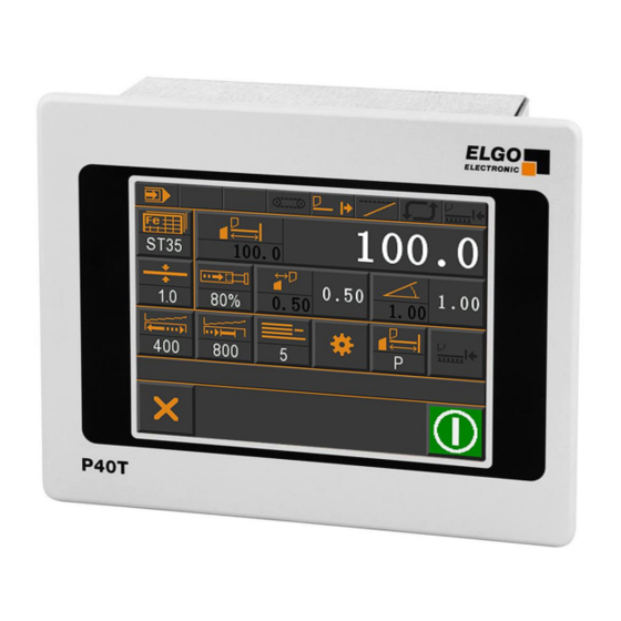
Programmable Touch Screen Controller for Guillotine Shears
TFT-Display with touch operation
Manual inching, single and program mode
Integrated program memory and auto-cutting machine
Material depending calculation of gap, angle & pressure
Sheet support and return to the front function
Analog inputs and outputs
Digital outputs up to 2 A
Advertisement
Table of Contents

Summary of Contents for Elgo P40T-002 Series
- Page 1 799000681 / Rev. 7 / 2019-05-13 Translation of the original operating manual Operating Manual SERIES P40T-002 Programmable Touch Screen Controller for Guillotine Shears TFT-Display with touch operation Manual inching, single and program mode Integrated program memory and auto-cutting machine ...
- Page 2 +49 (0) 7731 9339 - 0 +49 (0) 7731 2 88 03 info@elgo.de Document- No. 799000681 Document- Name P40T-002-MA-E_20-19 Document- Revision Rev. 7 Issue Date 2019-05-13 Copyright © 2019, ELGO Electronic GmbH & Co. KG - 2 -...
-
Page 3: Table Of Contents
Contents 1 Contents Contents ..................... 3 List of Figures ..................5 List of Tables ..................6 General, Safety, Transport and Storage ........... 7 Information Operating Manual ................... 7 Explanation of Symbols ...................... 7 Statement of Warranties ..................... 8 Demounting and Disposal ....................8 General Causes of Risk ..................... - Page 4 Contents 11.5 Distances Axis ........................ 32 11.6 Times Axis ........................37 11.7 Analog Axis ........................39 11.8 Calibrate Axis ......................... 43 11.9 Sub Menu Cutting ......................45 11.10 Sub Menu Setting System ....................47 11.11 Sub Menu Times System ....................49 11.12 Additional Functions ......................
-
Page 5: List Of Figures
List of Figures 2 List of Figures Figure 1: P40T - Touch Panel ........................10 Figure 2: Type label ..........................11 Figure 3: Dimensions P40T ........................11 Figure 4: Mounting into panel cut-out ...................... 14 Figure 5: Menu Structure ......................... 15 Figure 6: Start Screen / Main Menu ...................... -
Page 6: List Of Tables
List of Tables 3 List of Tables Table 1: Define Type of Axes ........................28 Table 2: Soft Keys ........................... 55 Table 3: Interpolation Procedure ......................58 Table 4: Parameter list - Setting System ..................... 66 Table 5: Parameter list - Time System ....................... 66 Table 6: Parameter list - Axis Backgauge .................... -
Page 7: General, Safety, Transport And Storage
General, Safety, Transport and Storage 4 General, Safety, Transport and Storage Information Operating Manual This manual contains important information regarding the handling of the device. For your own safety and operational safety, please ob- serve all safety warnings and instructions. Precondition for safe operation is the compliance with the specified safety and handling instruc- tions. -
Page 8: Statement Of Warranties
General, Safety, Transport and Storage Statement of Warranties The producer guarantees the functional capability of the process engineering and the selected parameters. Demounting and Disposal Unless acceptance and disposal of returned goods are agreed upon, demount the device considering the safety instructions of this manual and dispose it with respect to the environment. -
Page 9: Conventional Use
General, Safety, Transport and Storage Conventional Use The device is only conceived for the conventional use described in this manual. The ELGO device type P40T-002 serves exclusively for positioning and automatic cutting on guillotine shears. CAUTION! Danger through non-conventional use! Non-intended use and non-observance of this operating manual can lead to dangerous situations. -
Page 10: Product Features
Product Features 5 Product Features P40T-002 is a compact, programmable multi-axis positioning controller with touchscreen panel, designed for axis positioning and cutting automation on guillotine shears. Overview of features: 16 free programmable digital in-/outputs. Analog or digital outputs for 1 - 3 speed operation. ... -
Page 11: Technical Data
The type label of the P40T-002 serves for the identification of the unit. It is located on the housing of the device and indicates the exact type designation (=order reference 15) with the corresponding part number. Further- more, the type label contains a unique, traceable device number. When corresponding with ELGO please al- ways indicate this data. -
Page 12: Technical Data
Technical Data Technical Data P40T-002 (version for guillotine shears) Mechanical Data Housing panel housing Housing material front plate: aluminium| housing: galvanized steel sheet Front plate dimensions W x H = 180 x 144 mm Housing dimensions W x H = 136 x 136 mm Panel cut out W x H = 138 x 138 mm Keyboard... -
Page 13: Installation And First Start-Up
In case of damage caused by failure to observe this operating manual, the warranty expires. ELGO is not liable for any secondary damage and for damage to persons, property or assets. The operator is obliged to take appropriate safety measures. -
Page 14: Mounting Of The Controller
Installation and First Start-Up Mounting of the Controller The P40T-002 controller is intended for installation into a 138 x 138 mm panel cut-out. Required tools: 1 slotted screwdriver and 1 Phillips screwdriver. Panel Panel Phillips- head screw Grub Mounting screw (2 x) bracket (2 x) Panel rear Figure 4: Mounting into panel cut-out... -
Page 15: Design Und Function
Design und Function 8 Design und Function The device is operated via touch screen. The selection is made by touching the corresponding buttons. Menu Structure Main Menu Manual Single Program Service (Parameters) Operation Modes Figure 5: Menu Structure 8.1.1 Password NOTE! The service mode / parameter level is protected by password. -
Page 16: Main Menu
Main Menu 9 Main Menu After switching on the positioning control, the main menu opens. This contains the selection for the operating modes, menu languages, parameter settings in service mode (password input required 8.1.1) and the clean- ing function. Cleaning Countdown Cleaning... -
Page 17: Operation Modes
Operation Modes 10 Operation Modes 10.1 Single Mode In single mode, a single block can be processed. Each entered target position must be confirmed with “OK”. In single mode it is also possible to load the target position for the axis “Angle” and “Gap” from a material table. -
Page 18: Figure 10: Select Material From List
Operation Modes Consecutive material number Short Name Scroll Plain text field for material description Scroll Exit list Figure 10: Select material from list 10.1.1 Piece Counter The piece counter can be configured in 3 modes: Downwards counter Upwards counter ... -
Page 19: Figure 12: Downwards Piece Counter
Operation Modes 10.1.1.1 Downwards Piece Counter The piece counter is decremented after each complete cut until the number 0 is reached. Counts downwards (negative sign) Figure 12: Downwards piece counter 10.1.1.2 Upwards Piece Counter The piece counter is incremented after each complete cut. A value can be specified at which counting is started. Counts upwards (positive sign) Figure 13: Upwards piece counter... -
Page 20: Manual Mode
Operation Modes 10.1.1.3 Piece Counter disabled The cuts are not counted when the piece counter is disabled. Does not count (empty field) Figure 14: Piece counter disabled 10.2 Manual Mode In the manual inching mode, the axes can be moved manually. Simply activate the corresponding axis and move to the demanded position by using the buttons “+”... -
Page 21: Program Mode
Operation Modes 10.3 Program Mode In program mode, programs can be created, saved and executed. The material properties can be changed via the material table. This is loaded by pressing the material selection key for longer than 5 seconds. After releasing the key, the material table opens. Either the password 2505 for the material table or the service password (250565) is required for access. -
Page 22: Figure 17: Numeric And Alphanumeric Input Field
Operation Modes Clear entry Escape / Back Change sign Enter Switch between Clear last entry upper and lower case letters Enter Escape / Back Clear entry Figure 17: Numeric and alphanumeric input field 10.3.1 Cycle Counter in Program Mode In program mode, the controller has a cycle counter with 3 different modes: Cycle counter disabled Upwards counter: If the program has been executed, it starts again from the beginning and the cycle counter is incremented. -
Page 23: Figure 18: Define The "End Of Program
Operation Modes 10.3.2 Create a Program Following parameters and values are valid for the entire program (resp. are similar for all program blocks): Material type Material thickness Pressure Angle 1. Select a free program from the program list ( 10.3 Program Mode) resp. delete an existing program. Now the current data set should be 1. -
Page 24: Reference An Axis
Operation Modes 10.4 Reference an Axis The following parameter settings can be selected in the menu Sub Menu Axis -> General Axis General -> Mode reference ( 11.4.2 Reference Mode): 1. MODE 1(by parameters): If the external reference input is active or the button “Reference” will be pressed for more than 3 seconds, the value stored in register Sub Menu Axis ... -
Page 25: Service Mode / Parameter Level
Service Mode / Parameter Level 11 Service Mode / Parameter Level Parameters are set in the service mode. An overview of all parameters can be found in 13 Parameter Tables. 11.1 Service Menu The service menu can only be accessed after successful login (see 11.2 Password Login). Sub Menu Sub Menu Axes Settings System... -
Page 26: Sub Menu Axis
Service Mode / Parameter Level 11.3 Sub Menu Axis With this menu all axis parameters can be selected and edited in the corresponding sub level. Figure 21: Sub Menu Axis - 26 -... -
Page 27: Settings Axis
Service Mode / Parameter Level 11.4 Settings Axis With this menu the general axis parameter settings of the respective axis can be done. Escape / one level back Selection Backgauge / Gap / Angle Figure 22: Settings Axis (general) - 27 -... -
Page 28: Table 1: Define Type Of Axes
Service Mode / Parameter Level 11.4.1 Axis Type IN / OUT Table 1: Define Type of Axes Backgauge Parameters Gap and Angle Parameters Encoder – Analog+Dig Disabled Analog – Analog+Dig Encoder – Analog+Dig Encoder – Digital Analog – Analog+Dig Encoder – PID+Digital Encoder –... - Page 29 Service Mode / Parameter Level 11.4.5 Drive Signal Configuration With configuration of the motor signals different starting combinations for the different speeds can be set. Drive Signals Mode 1 3 speeds Speed = output signals 1-3 ascending Output 4 sets direction backwards Output signals Creep speed forward Slow speed forward...
- Page 30 Service Mode / Parameter Level Drive signals Mode 4 2 speeds Independent outputs for direction and speed Output signals Creep speed forward Fast speed forward Creep speed backward Fast speed backward Drive signals Mode 5 3 speeds Speed forward = output signals 1-3 ascending Speed backward = always fast output 4 sets direction backwards...
- Page 31 Service Mode / Parameter Level Drive signals Mode 7 3 speed Forward/backward separately Output signals Creep speed forward Slow speed forward Fast speed forward Creep speed backward Slow speed backward Fast speed backward Drive signals Mode 8 2 speeds Forward/backward separately Output signals...
-
Page 32: Distances Axis
Service Mode / Parameter Level 11.5 Distances Axis Relevant distance parameters can be set in this menu for the selected axes. Escape / one level back Selection Backgauge / Gap / Angle Figure 23: Axis Distances - 32 -... -
Page 33: Figure 24: Creep Speed (1 Speed)
Service Mode / Parameter Level 11.5.1 Creep Speed / Correction Stop Creep speed (forward / backward) = slow speed Distance to the target position at which the controller switches from slow speed to creep speed. The output slow speed will be switched off. Correction Stop (forward) / Correction Stop (backward) This parameter serves to compensate the overrun distance from the switch-off point of the motor to standstill. -
Page 34: Figure 25: Creep Speed (2 Speeds)
Configuration and Functions Service Mode / Parameter Level Example: Positioning with 2 speeds In principle, the following applies when setting the speeds: Creep speed > Correction stop Creep speed = 10.0 Correction = 1.0 Fast speed Target: 100.0 mm Creep speed Correction stop Slow 90.0 mm... - Page 35 Service Mode / Parameter Level 11.5.2 Tolerance Window The tolerance window is reached when the actual value is equal to the target value ± parameter "Tolerance Window". If an axis is within the tolerance window, it is not moved when a new start command is issued. The respective “Tolerance Zone”...
- Page 36 Service Mode / Parameter Level 11.5.9 Factor Here the pulse scaling factor (for mm as measuring unit) is set. The incoming encoder pulses are multiplied by this factor (range 0.00001 to 9.9999) to customize the display to the desired position values. Beispiel: [Pulses] Encoder = 1000...
-
Page 37: Times Axis
Service Mode / Parameter Level 11.6 Times Axis Relevant time parameters for the respective axis can be set in this menu. Escape / one level back Selection Backgauge / Gap / Angle Figure 27: Axis Times - 37 -... - Page 38 Service Mode / Parameter Level 11.6.1 Position Reached The output signal is wiping when a time is entered or static when zero is set. It is set when the positioning of the corresponding axis is completed. 11.6.2 Spindle Compensation At the peak of the loop run, the drive signals drop off. Only after this time has elapsed, the controller returns to the target value (adjustment range 0.1 sec …...
-
Page 39: Analog Axis
Service Mode / Parameter Level 11.7 Analog Axis Relevant analog parameters for the respective axis can be set here: Escape / one level back Selection Backgauge / Gap / Angle Figure 28: Axis Analog - 39 -... - Page 40 Service Mode / Parameter Level 11.7.1 Velocity The maximum speed per minute for positioning is defined here. The speed is measured via the rotary encoder (0 ... 10000 rpm). If there is a transmission between the motor and the rotary encoder (e.g. by a gear or a spin- dle), the transmission ratio must be taken into account for the number of revolutions.
- Page 41 Service Mode / Parameter Level 11.7.5 I-Portion / I-Limit Integral step: setting range 1 … 1000 General: An I-controller (integrating controller) determines the output value by integrating the control deviation with weighting by the reset time. A continuous control deviation therefore leads to a further increase of the control output.
- Page 42 Service Mode / Parameter Level 11.7.12 U<< / U>> This register is used to set the voltage during slow speed operation backwards / forwards. 11.7.13 U< / U> This register is used to set the voltage during creep speed backwards / forwards. 11.7.14 Stop Mode For the different possibilities to stop the system the P40T comes with this special register.
-
Page 43: Calibrate Axis
Service Mode / Parameter Level 11.8 Calibrate Axis 11.8.1 Calibration with Axis Angle 1. Input of the min. and max. value to be calibrated. 2. Activate axis. 3. Move axis accordingly (measure min/max manually). 4. Set Increment value (inc) by „Teach“ field. 5. -
Page 44: Figure 30: Calibration Without Axis Angle
Service Mode / Parameter Level 11.8.2 Calibration without Axis Angle 1. Input of min. and max. values to be calibrated. 2. Activate axis. 3. Move axis accordingly (measure min/max manually). 4. Set Increment value by the „Teach“ field. With deactivated axis the according inc values can be readjusted. Following machine values are set directly: (Left) blade opening at TDC (Top Dead Center). -
Page 45: Sub Menu Cutting
Service Mode / Parameter Level 11.9 Sub Menu Cutting Figure 31: Sub Menu Cutting 11.9.1 Cut Time This parameter defines the time from start of cutting until end of cutting. 11.9.2 Offset Cut Time This parameter defines the time from the upper rest position to the start of the cut that the blade needs to lower. - 45 -... - Page 46 Service Mode / Parameter Level 11.9.3 Mode Cutlength OFF via axis angle (default setting) via time by foot pedal (the blade moves downwards until either the foot pedal is released, or the BDC switch is reached. The blade then moves upwards again). 11.9.4 Pressure Blade up Defines the pressure in % at which the knife is lifted back to the upper rest position.
-
Page 47: Sub Menu Setting System
Service Mode / Parameter Level 11.10 Sub Menu Setting System In this sub menu system parameter can be set. By pressing the button "pressure active for testing" (see figure below) additionally the setting "U at 100 % pressure" can be activated for testing purposes. Button „pressure active for testing“... - Page 48 Service Mode / Parameter Level 11.10.3 Pressure Adjust Angle This parameter defines the pressure in percent to adjust the angle. 11.10.4 Pressure Adjust Gap This parameter defines the pressure in percent to adjust the gap. 11.10.5 Gap / Angle / Pressure locked ...
-
Page 49: Sub Menu Times System
Service Mode / Parameter Level 11.11 Sub Menu Times System Figure 33: System Times - 49 -... - Page 50 Service Mode / Parameter Level 11.11.1 Preparations for Activation of the Sheet Support 1. Please check whether the software is V2.13 or higher has been installed 2. The inputs and outputs must be assigned (see also 11.17 Functional and Logical Assignment of Input-/Output Functions). Inputs: Sheet Support may have 2 or 3 positions: if you assign the Input "support is up"...
- Page 51 Service Mode / Parameter Level 2. 3-position-support with 3 positions (up/middle/down) a. after “start cut”, time “support delay” runs b. after time “support delay” elapsed, output “support down” is set P40T waits for Input "support in middle” d. output “support down” is reset e.
-
Page 52: Additional Functions
Service Mode / Parameter Level 11.12 Additional Functions Figure 34: Additional Functions 11.12.1 Min Sheet Length RTO Min sheet length for the RTO function push sheet to operator (Return To Operator). 11.12.2 Max Sheet Length RTO Max sheet length for the RTO function push sheet to operator (Return To Operator). 11.12.3 Min Sheet Thickness RTO Min sheet thickness for the RTO function ... -
Page 53: Pump Control
Service Mode / Parameter Level 11.13 Pump Control With the P40T-002 it is possible to control a pump via a digital output. The pump control is activated by assign- ing the output “Pump on” to any output pin ( 11.17). When pump control is activated, a button for switching the pump control output on and off is displayed in the main menu: Pump is OFF... -
Page 54: Calibrate (Touch Screen)
Service Mode / Parameter Level 11.14 Calibrate (Touch Screen) In this menu the touch screen can be calibrated: Figure 38: Calibration Touch Screen 1. Activate the calibration field. 2. Follow the displayed instructions "Touch Corner and Hold" in the respective corner. 3. -
Page 55: Soft Keys
Service Mode / Parameter Level 11.15 Soft Keys This menu can be used to make the settings for the soft keys. The table below shows the corresponding options. A maximum of 5 soft key options can be activated simultaneously. If a further option is activated, an error message appears. Figure 39: Soft-Keys Table 2: Soft Keys ON = active / OFF = not active... - Page 56 Service Mode / Parameter Level 11.15.1 Conveyor Belt Function: The output “conveyor belt” is set if: 1. The function is activated by soft key in single or program mode 2. The cutter bar is in the Top Dead Center Since the state is not saved, the conveyor belt function must be reactivated each time the single or program mode is selected.
-
Page 57: Material Table
Service Mode / Parameter Level 11.16 Material Table In this table the material-specific empirical values regarding cutting angle, cutting gap and cutting pressure can be entered. When processing one or more blocks, only the material type (material No.) and the sheet thickness must be entered. -
Page 58: Table 3: Interpolation Procedure
Service Mode / Parameter Level 11.16.1 Explanation of the Interpolation Procedure Since only a limited number of values in 0.1mm steps can be stored in this table, the values in between are interpolated. The calculation of the intermediate steps is based on a linear behavior of the values for angle and gap between two successive material thicknesses. -
Page 59: Functional And Logical Assignment Of Input-/Output Functions
Service Mode / Parameter Level 11.17 Functional and Logical Assignment of Input-/Output Functions The input and outputs of the controller are set with functions (see chapter 12 Connections). In this menu item you can define whether the corresponding input/output function is to be triggered at a logical HIGH level or at a logical LOW level. -
Page 60: Load And Save Oem Data
Service Mode / Parameter Level 11.18 Load and Save OEM Data The loading/storing of the OEM parameters must be confirmed by entering the password (see 8.1.1) again. Load OEM data Save OEM data Figure 42: Load and save OEM data 11.19 Reset to Factory Defaults A reset to the default parameters must be confirmed by entering the password (see ... -
Page 61: Touchscreen Design / Program Version / Backup Id
Service Mode / Parameter Level 11.20 Touchscreen Design / Program Version / Backup ID This menu allows customizing the color design of the background, fields (icons), text foreground and text back- ground. In addition, the program version and backup ID are displayed (important when backing/loading via the PC software "Backup Tool"). -
Page 62: Connections
Connections 12 Connections The following sections provide detailed information on the connections: 12.1 Connector Arrangement - 16 IO Version MCC1 MCC2 Figure 46: Connector arrangement - 16 IO Connector No. Function ST1 Measuring system connections (encoder inputs) ST2 Measuring system connections (analog inputs) ST3/ST4 Digital inputs ST5/ST6 Digital outputs ST7 Analog output 1 (PID) -
Page 63: Pin Assignment - 16 Io Version
Connections 12.2 Pin Assignment - 16 IO Version Inkremental Encoder Analog Measuring System 0 V / GND out 0 V / GND out + 24 VDC out (optionally 5 VDC) 3.3 VDC out (reference voltage) Channel A Analog input “Gap 1“ Channel B do not connect PE / Earth... -
Page 64: Connector Arrangement - 8 Io Version
Connections 12.3 Connector Arrangement - 8 IO Version MCC1 MCC2 Figure 47: Connector arrangement - 8 IO Connector No. Function ST1 Measuring system connections (encoder inputs) ST2 Measuring system connections (analog inputs) ST3 Digital inputs ST5 Digital outputs ST7 Analog output 1 (PID) ST8 Analog output 2 (pressure control) ST9 24 VDC power supply voltage S12 PC interface (adapter cable see ... -
Page 65: Pin Assignment - 8 Io Version
Connections 12.4 Pin Assignment - 8 IO Version Inkremental Encoder Analog Measuring System 0 V / GND out 0 V / GND out + 24 VDC out (optionally 5 VDC) 3,3 VDC out (reference voltage) Channel A Analog input “Gap1” Channel B do not connect PE / Earth... -
Page 66: Parameter Tables
Parameter Tables 13 Parameter Tables 13.1 Parameter Setting System Table 4: Parameter list - Setting System Function Setting Range Factory Setting Customer Setting Pressure Control on / off U at 100% pressure 0 – 10 Pressure adjust angle 0 – 100 40 % Pressure adjust gap 0 –... -
Page 67: Table 7: Parameter List - Axis Gap
Parameter Tables Table 7: Parameter list - Axis Gap Function Setting Range Factory Setting Customer Setting Encoder - Digital Encoder - PID+Digital disabled Axis Type IN / OUT Analog - Digital Encoder - Analog+Digital Encoder - Analog+Digital Reference mode Mode 1 / Mode 2 / Mode 3 Mode 1 both enabled negative disabled... -
Page 68: Table 9: Parameter List - Distance Axis Backgauge
Parameter Tables Table 9: Parameter list - Distance Axis Backgauge Function Setting Range Factory Setting Customer Setting Creep speed 0.0 … 1000.0 10.0 Tolerance window 0.0 … 100.0 Spindle compensation 0.0 … 1000.0 Reference value -10000.0 … 100000.0 30.0 End position min 0.5 …... -
Page 69: Table 12: Parameter List - Time Axis Backgauge
Parameter Tables Table 12: Parameter list - Time axis backgauge Function Setting range Factory setting Customer setting Position reached 0.0 … 10.0 Manual change 0.0 … 10.0 Delay contr. Start 0.0 … 10.0 Delay contr. Inpos. 0.0 … 10.0 Start delay 0.0 …... -
Page 70: Parameter Sub Menu Cutting
Parameter Tables Table 15: Parameter list - Analog axis Function Setting Range Factory Setting Customer Setting Velocity 0 … 10000 2000 Acceleration 0 … 1000 Pulses encoder 0 … 10000 P portion 0 … 100 I portion 0 … 100 D portion l 0 …... -
Page 71: Parameter Sub Menu Soft Keys
Parameter Tables 13.6 Parameter Sub Menu Soft Keys Table 18: Parameter list - Sub Menu Soft Keys Function Setting Range Factory Setting Customer Setting Conveyor belt on / off Autocut on / off Park position (backgauge) on / off 3.0 … Park position (backgauge) backgauge-distance ... -
Page 72: Table 22: Parameter List - Digital Output At St5
Parameter Tables Table 22: Parameter list - Digital Output at ST5 Function Setting Range Factory Setting Customer Setting P3 Drive signal 1 gauge HIGH / LOW HIGH P4 Drive signal 4 gauge HIGH / LOW HIGH P5 F Drive signal 3 gauge HIGH / LOW HIGH P6 Control enable gauge... -
Page 73: Disturbances, Maintenance, Cleaning
Disturbances, Maintenance, Cleaning 14 Disturbances, Maintenance, Cleaning This chapter describes possible causes for disturbances and measures for their removal. In case of increased disturbances, please follow the measures for fault clearance in chapter 14.1. In case of disturbances that cannot be eliminated by following the advice and the fault clear- ance measures given here, please contact the manufacturer (see second page). -
Page 74: Possible Errors And Their Clearance
Disturbances, Maintenance, Cleaning 14.2 Possible Errors and their Clearance Table 24: Possible Errors and their Clearance Message Required Action Hardware end switch minimum gauge active! check signal/connection of input / deactivate function if necessary Hardware end switch minimum gap1 active! check signal/connection of input / deactivate function if necessary Hardware end switch minimum angle active! check signal/connection of input / deactivate function if necessary... -
Page 75: Re-Start After Fault Clearance
Disturbances, Maintenance, Cleaning 14.3 Re-start after Fault Clearance After the fault clearance: Reset the emergency stop mechanism if necessary Reset the error report at the super-ordinate system if necessary. Ensure that there are no persons in the danger area. Follow the instructions from chapter 7. WARNING! Danger of injury through non-conventional fault clearance! Non-conventional fault clearance can lead to severe injuries and damage of property. -
Page 76: Type Designation
Type Designation 15 Type Designation P40T - 000 XXXX Type Designation: P40T = Touchscreen Position Controller (for 1 or 2 axes) Version: 002 = Version for guillotine shears Power Supply Voltage: 024 = 24 VDC (+10 / -20 %) Encoder Inputs (per Axis): = Input is not available = A, B, Z (PNP) 24 V supply / HTL, 100 kHz... -
Page 77: Accessories
Type Designation 15.1 Accessories Table 25: Accessories Order Designation Description NG 24.0 Power supply unit for supply with AC-voltage: - 115/230 VAC in / 24 VDC out (max. 600 mA) - with screw terminals for 2 x 2.5 mm wires - Dimensions W x H x D = 75 x 73 x 114 mm Adapter cable for connecting a P40T to a PC via the RS232 interface. -
Page 78: Appendix
Appendix 16 Appendix Connection examples: backward forward GND (0V) 24 VDC Earth I/O EA GND (0V) I/O EA-24VDC Switch endposition „gab-min.“ Switch endposition „gab-max.“ Start cut (food pedal) Top dead center Bottom dead center Piece counter Support is up Support is down GND (0V) Earth GND (0V) - Page 79 Appendix backward forward GND (0V) 24 VDC Earth I/O EA GND (0V) I/O EA-24VDC Switch endposition „gab-min.“ Switch endposition „gab-max.“ Start cut (food pedal) Top dead center Bottom dead center Piece counter Support is up Support is down GND (0V) Earth GND (0V) Earth...
- Page 80 Appendix GND (0V) 24 VDC Earth I/O EA GND (0V) I/O EA-24VDC Switch endposition „gab-min.“ Switch endposition „gab-max.“ Reference start „Gauge“ Start extern Stop extern I/O EA GND (0V) I/O EA-24VDC Piece counter Top dead center Bottom dead center Support is up Support is down Start cup ( foot pedal) GND (0V)
- Page 81 Appendix fast backward forward GND (0V) 24 VDC Earth I/O EA GND (0V) I/O EA-24VDC Switch endposition „gab-min.“ Switch endposition „gab-max.“ Reference start „Gauge“ Start extern Stop extern I/O EA GND (0V) I/O EA-24VDC Piece counter Top dead center Bottom dead center Support is up Support is down Start cup ( foot pedal)
- Page 82 Appendix 0...10V 0V-GND Schild GND (0V) 24 VDC Earth Ein/(Aus)gang EA GND (0V) Ein/(Aus)gang EA-24VDC Endschalter „Anschlag-min.“ Endschalter „Anschlag-max.“ Referenz Start „Referenz“ Start extern Stop extern Ein/(Aus)gang EA GND (0V) Ein/(Aus)gang EA-24VDC Stückzähler Oberer Totpunkt Unterer Totpunkt Support ist oben Support ist unten Schitt starten Fußbedal GND (0V)
- Page 83 Notes: - 83 -...
- Page 84 Notes: - 84 -...
- Page 85 Notes: - 85 -...
-
Page 86: Index
Index 17 Index Acceleration ............40 Manual Mode ............20 Accessories ............77 Manual Slow ............41 Accident prevention regulations ........7 Material Properties ..........17 Activation of the Device ........... 14 Material Table ............57 Additional Functions ..........52 Menu Structure ............ - Page 87 Index Storage ..............9 Time Down Holder ..........46 Sub Menu Axis ............26 Tolerance Window ..........35 Sub Menu Cutting ........... 45 Touchscreen Design / Program Version / Backup ID ... 61 Sub Menu Setting System ......... 47 Transport ..............9 Sub Menu Time System ..........
- Page 88 Document- No.: 799000681 / Rev. 7 ELGO Electronic GmbH & Co. KG Measuring | Positioning | Control Document- Name: P40T-002-MA-E_20-19 Carl - Benz - Str. 1, D-78239 Rielasingen Subject to change - © 2019 Fon:+49 (0) 7731 9339-0, Fax:+49 (0) 7731 28803 Internet: www.elgo.de, Mail: info@elgo.de...
Need help?
Do you have a question about the P40T-002 Series and is the answer not in the manual?
Questions and answers
Vì sao màn hình của tôi bật máy lên chỉ có sáng trắng không có biểu tượng nào để dùng cả