Table of Contents
Advertisement
(IMPORT & EXPORT DEPT.)
OSAKA
15-7, 2-Chome, Hishie, Higashi-Osaka city, Osaka
14-1, 5-Chome, ND bldg.,7F, Ueno, Taito-ku, Tokyo TEL ( 03 ) 5807-6434 FAX ( 03 ) 3834-2098
TOKYO
NAGOYA 210, 2-Chome, Sakuta, Nagakute city, Aichi
OSAKA
15-7, 2-Chome, Hishie, Higashi-Osaka city, Osaka
TEL (072)966-9011 FAX (072)966-9017
TEL ( 0561 ) 64-2331 FAX ( 0561 ) 64-2332
TEL ( 072 ) 966-9011 FAX ( 072 ) 966-9017
Instruction Manual
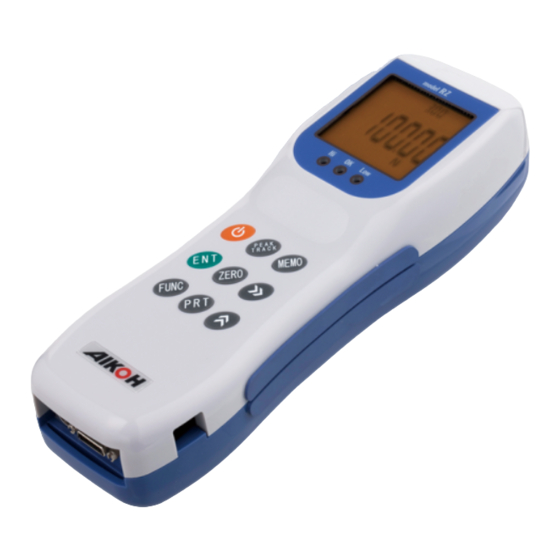
Digital Force Gage
Model RZ
This instruction manual covers both Model RZ Series and
Model RZ-T Series.
Please read this instruction manual
thoroughly before using the gage for
the first time.
This manual is very important when using the product.
Keep it near the product in such a way that it can be
referred to at any time necessary.
Series
Advertisement
Table of Contents

Summary of Contents for Aikoh Engineering RZ Series
- Page 1 Instruction Manual Digital Force Gage Model RZ Series This instruction manual covers both Model RZ Series and Model RZ-T Series. Please read this instruction manual thoroughly before using the gage for the first time. This manual is very important when using the product. Keep it near the product in such a way that it can be referred to at any time necessary. (IMPORT & EXPORT DEPT.) OSAKA 15-7, 2-Chome, Hishie, Higashi-Osaka city, Osaka TEL (072)966-9011 FAX (072)966-9017 14-1, 5-Chome, ND bldg.,7F, Ueno, Taito-ku, Tokyo TEL ( 03 ) 5807-6434 FAX ( 03 ) 3834-2098 TOKYO TEL ( 0561 ) 64-2331 FAX ( 0561 ) 64-2332 NAGOYA 210, 2-Chome, Sakuta, Nagakute city, Aichi...
-
Page 2: Table Of Contents
Table of Contents To Users of Our Digital Force Gages Precautions for Use 1. Safety Precautions ……………………………………………1 〜 3 About Overload Thank you for purchasing our products. 2. Checking the Contents of the Package …………………4 Our Service Section analyzed the cause of troubles of our digital Force gages and 3. Nomenclature ……………………………………………………5 found that the cause of the most frequent troubles is Overload (O.L.) . 4. Description of the Display ……………………………………6 〜 7 If a force exceeding the withstand load is applied to the load cell, the load cell itself 5. Prior to Use ………………………………………………………8 is distorted permanently and cannot return to the original condition. This status of 6. Setting of Each Mode …………………………………………9 〜 10 the load cell is called Overload (O.L.) . The load cell converts small amount of distortion of metal into very low voltage 7. Flow of Mode Screen Selection ……………………………11 and outputs converted voltage. 7-1. Setting of the comparator function …………………12 The metal can return to the original condition if the applied load is within the ... -
Page 3: Safety Precautions
Safety Precautions WARNING The precautions presented below are very important for safety and must be observed strictly. The symbols and their meanings are as follows. When performing measurement which Make sure that the will destroy or cut an object to Indicates that it is highly possible that the user will object being measured measure, wear equipment to protect DANGER・・・・ suffer serious injury or loss of life or indicates the will not fly off. yourself from broken pieces hitting possibility of serious consequences depending on your eyes or body. situations due to the structure and characteristics of the product if the product is not used properly. The hook may be broken or slip out of Indicates the possibility that the user may suffer WARNING・・・ Do not use a damaged your hand to cause injury. Or the serious injury or loss of life if the product is not used hook or deformed hook. object being measured may fall to properly. cause serious injury. Indicates the possibility of minor personal injury if the CAUTION・・・ product is not used properly. Be sure to insert the AC Loose connection may cause a short adapter to the circuit which can result in electric receptacle fully. shock or fire. DANGER CAUTION Charging will be completed in about 4.5 hours. Charging longer than 24 hours will cause the ... -
Page 4: Checking The Contents Of The Package
Checking the Contents of the Package CAUTION Prior to use, make sure that the following items are contained: The force sensor may be broken. Do not apply a force Application of a larger force may break exceeding the rated the body case or internal components 1. RZ gage 2. AC adapter MODEL-780 3. European spec capacity. replacement plug to cause accidents. ・An environment where the gage may be exposed to water. Do not use or store the ・An environment where condensation 4. USB cable Model RZ-USB 5. Instruction manual 6. Warranty gage in the may occur. environment described ・A dusty environment. on the right side: ・An environment where the gage may be exposed to oil or chemicals. The use of the gage outside the Use the gage within its working temperature range may cause 7. Measurement attachments (RZ-1 (10N) is made of aluminum.) working temperature malfunction. The working humidity (RZ-100 (1000N): Only 011B has a larger diameter.) range (0 to +40℃). range is 20% to 60% RH. 011B 012B 013B 014B 015B 016B... -
Page 5: Nomenclature
Comparator judgment LED Display Measuring shaft Nomenclature Description of the Display PEAK TRACK Power ON/OFF This is a sub display for setting and indicates the tensile peak value and a value when the contact is off. ZERO Indicates the remaining FUNC battery charge. MEMO PHMC Indicates the measured Lights/flashes when the peak force value. value is being indicated. For about 3 seconds after Printer output the power is turned on, the Lights/flashes in the external connector max. force value used and contact hold mode. the software version are shown. During measurement, I/O connector USB connector Lights when data is memorized. a measured value is shown. Lights in the comparator Description of the component devices setting mode. Kgf N The minus sign is shown when ×1000 ① Measuring shaft ... -
Page 6: Prior To Use
M (Memory mode) (For storing data in memory, see page 20.) Prior to Use Maximum 500 pieces of data or 500 sets of data can be stored in the memory. When data is being stored, this mark lights up. Pressing the key records the measured value and the number of pieces of recorded data is shown at the bottom. Both PEAK and TRACK values are recorded. However, since the first memory <Charging> conditions are fixed, changing PEAK/TRACK and units of measurement are not allowed in the second and following operations. To store data after changing the conditions, press the key with the The use of an adapter other than the included key held pressed to clear all stored data once. As soon as data has been Be sure to use the AC adapter will destroy the accuracy and in a cleared, the mark M will go out and the number of pieces of data will included AC adapter. become zero momentarily and then go out. worse case, may cause malfunction or fire. Only when the mark P is shown lit in the peak mode, the compressive peak value and tensile peak value are stored as a set in the memory. The gage has been charged in the factory, but since a minute current is consumed P (Peak mode) even when the power is off, the charging level might have dropped. Prior to use, charge the gage with the included AC adapter. Each time the key is pressed, P changes its status as flashing → on → off. USB connector P flashing・・・・・The highest measured value of either tensile or compressive value is acquired as the peak value. - Page 7 User Setting Mode ③ On the setting screen, change the setting with the key. <Mode selection and setting> When the setting is such as ON-OFF, select either one with the key and accept it with the ① Pressing and holding the key for 3 seconds or key and then return to the select screen. longer sets the user setting mode. To enter a numeric value, follow the steps below. At the beginning, the following mode select screen will appear. Go to a desired digit with the key and enter a ④ numeric value with the key. The minus sign is added with the key. (When the sign − is shown, it is a compression value and when no sign is shown, it is a tension ② value.) Go to 01 to 13 with the key and select it with After moving it to a digit to set or change, select the key. a value to set with the key. On the setting screen, the name of the selected mode is shown at the top. To add the minus sign, press the key. Then the sign − will be shown on the left side of the value. When the key is pressed again, the sign − will go out, indicating that the value is a plus value. ⑤ Accept the value with the key and return to the mode select screen with the key.
-
Page 8: Flow Of Mode Screen Selection
Flow of Mode Screen Selection Setting of the Comparator Function (Comparator function enable/disable and ※For the setting procedure, see page 9. upper/lower limit value setting) (Comparator function enable/disable and upper/lower limit value setting) (Stand control upper limit value action function setting) When On (enable) is set in the On (enable)/ Off (disable) selection, the procedure will go to a step of entering a numeric value of HI (upper limit (Stand control lower limit value action value) or LO (lower limit value). function setting) The status of the force value, whether within the range or outside the plus/minus range of the entered set value is indicated by the LED and can be known by corresponding signals output from the I/O connector. (Stand control upper limit value setting) If the setting of the upper limit value/lower limit value is not correct, the warning buzzer sounds to inform that the setting is not acceptable. The LED indication and output signals are as follows. (Stand control lower limit value setting) <LED> RZ series (Overload output direction change) Lights up when the set comparator lower limit (Screen display direction change) value has been reached or exceeded. Lights up when the force value is between the comparator upper limit value and lower limit value. Lights up when the set comparator upper limit value (Analog output zero adjustment) has been reached or exceeded. <Output signals> (Auto power off function enable/ 26-pin connector(Use the optional cable RZ-OP-2.)... -
Page 9: Concept Of The Upper Limit Value And Lower Limit Value
Setting of the stand control function Brief Explanation ※For the setting procedure, see page 9. Concept of the upper limit value and lower limit value (Stand control upper limit value action function setting) 1. When the set values of both the upper limit value (Stand control lower limit value action and lower limit value are on the plus (tension) function setting) side (A, B) in the figure, A which is larger is the upper limit value and B is the lower limit value. This setting is useful when Aikoh s electric test stand compatible with this gage is used in combination. By setting a desired force value, the test stand can be moved up/down or stopped when the actual force has reached the 2. When the set values of both the upper limit value force set value to protect the user s test sample and at the same time, and lower limit value are on the minus various tests can be controlled in force. There are four types of setting as (compression) side (D, C) in the figure, D which shown below, from which you can select one. is larger in absolute value is the upper limit value and C is the lower limit value. no (Disabled) UP (Up action) down (Down action) Stop (Stop) 3. When the set values of the upper limit value and ... -
Page 10: Precautions For Installation On The Electric Test Stand
Precautions for installation on the electric test stand Changing the screen display direction ※For the setting procedure, see page 9. ※For the setting procedure, see page 9. (Overload output direction change) (Screen display direction change) The display of the measured value and unit can be reversed. Use this If a force exceeding the rated capacity is applied to the measuring shaft, the function when mounting the gage on a test stand. force sensor may be broken and the gage may fail. The contents of setting and the display direction are as follows. When the gage is installed on Aikoh s electric test stand, an overload signal can be output from the 26-pin I/O connector to the electric test stand to stop the stand. For this purpose, it is necessary to make setting (UP)Upward selected (DOWN)Downward selected according to the action direction of the electric test stand and the direction of a force to be applied. allows selection of either or For a combination of Aikohʼs electric test stand Model 1308 and Model 2257, select ※To use the gage in combination with other electric test stand, confirm the stop direction prior to making this setting. If the setting is incorrect, even if an overload occurs, the electric test stand will not stop, breaking the force sensor. ※For connection, use the optional cable RZ-OP-1 or RZ-OP-2. Direction of the display when the Direction of the display when the measuring shaft faces upward. measuring shaft faces downward. Vertical/horizontal combined type MODEL-1308U MODEL-2257 Capacity / 1000N Capacity / 500N T h e g a g e m o u n t i n g This model is electrical ... -
Page 11: Using Analog Outputs
Using analog outputs Automatic zero resetting ※For the setting procedure, see page 9. ※For the setting procedure, see page 9. (Analog output zero adjustment) (Auto zero reset function enable/disable setting) An analog voltage is output constantly from the 26-pin connector provided at the bottom of the body. (Approx. ±2V at the rated capacity) With this setting at ON, when the indicated value is within two digits, it is The output pin numbers are as follows: possible to automatically apply automatic zero resetting every about 2 Analog output voltage ±2V/F.S. (Rated capacity) seconds. This function has been set to OFF in the factory. Rated capacity No. 19・ ・ ・Analog Out (±2V/F.S.) NO. 20・ ・ ・Analog GND (A.GND) (ON)Setting ON (OFF)Setting OFF ※For outputting a voltage, use the optional cable RZ-OP-2. The analog voltage is output in proportion to the actual force being applied to the sensor, regardless of the indicated value. Accordingly, a voltage proportional to the actual load by the orientation of the measuring shaft and the mass of the fixture is output. This is not eliminated Using the external zero resetting function when the indication is reset to zero, but by adjustment described here, the output voltage when zero resetting is performed can be brought close to zero. ※For setting, connect the optional cable RZ-OP-2 to the gage and connect a In addition to the key provided on the gage, it is possible to reset the force digital voltmeter to the signal line corresponding to the analog output pin No. value to zero by inputting an external zero reset signal to the 26-pin connector Then, select this item by the setting procedure presented on page 9. Using at the bottom of the gage. the key and key, change the figure forward or backward to make the ... -
Page 12: Changing Over Between 3 Units
Setting measurement conditions Measurement ① <Measurement by use of the memory function> (Data sampling time change) ■Collection of data by field measurement ※When data is collected with the memory function or when collected Change the internal sampling time of measured values. The memory function of this gage can store Select one from 1 ms, 5 ms, 16 ms, 50 ms, 125 ms and 250 ms. (Factory d a t a h a s b e e n s t o r e d i n t h e maximum 500 sets of measured force setting 50 ms) memory, ... - Page 13 ③ ① Checking the units Calling and deleting data Select a unit of measurement from N, Kgf and lb. Only the data that was stored last in the memory (3-unit system) can be called and deleted. Each time the key is pressed, the unit is shown When the key is pressed while pressing the below the force value in the order of Kgf, lb and N. key, the data stored last will be called. Then ※This function cannot be used when N has been pressing the key deletes the called data and the set. gage will return to the normal operation. If the key is pressed without pressing the key, the called data will be returned to the memory. ① ② ④ Force zero Press ② while pressing ①. Pressing the key without applying a force resets the indicated value to zero. Continue measurement. ② Printing data in the memory The printers that are connectable to this gage are the following two types: ①MITUTOYO-made DP-1VR (Mitutoyo Digimatic output connection) ※For connection, use the optional cable RZ-OP-3. ⑤ Storing and printing data ②SANEI ELECTRIC-made BL2-58SNWJC (RS232C If there is data that needs to be stored during connection) measurement, press the key. Then that data will ...
-
Page 14: Measurement
Measurement ② <Measurement procedure by use of the external contact hold function> <Measurement by use of the external contact hold> ①Connecting the RZ gage and a printer Connect the I/O connector at the bottom of the RZ gage and a printer with the When performing measurement which will destroy or optional cable. To connect to BL2-58SNWJC, use the optional cable RZ-OP-4 cut an object to measure, wear equipment to protect and to connect to DP-1VR, use the optional cable RZ-OP-3. yourself from broken pieces hitting your eyes or body. ②Connecting the external contact The external contact hold signal lines have been provided when the optional ■Measurement of switch/relay contact force ■Printer cable is used. They are Pin 14 (Hold In) and Pin 17 (GND) of the 26-pin connector at the bottom of the gage. External hold function (The continuous short-circuit/release values of OFF→ON→OFF are held and A force when a contact i s O N o r O F F c a n b e indicated.) measured. -
Page 15: Measurement
Measurement ③ Force Calibration Procedure <Connector mating/unmating measurement> ・The hook may be broken or slip out of your hand to Do not use a cause injury. Or the object being measured may fall to cause serious injury. damaged hook or ■For measurement of mating/ ・Apply a force to a point where the extension line deformed hook. unmating forces of connectors, etc. of the measuring shaft and the hook cross. If a force is applied to the tip of the hook, the hook Memory function of the gage may be deformed or broken to cause serious injury. A mating value and unmating value are stored in the memory and indicated by ・The force sensor may be broken. Application of a Do not apply a force larger force may break the body case or internal one operation. components to cause accidents. exceeding the rated ・The weight of the fixture will be loaded as a force. capacity. Use a fixture the weight of which is less than ①PEAK setting 10% of the rated capacity of the gage. Press the key to show P in the upper left corner of the screen. ・When securing an attachment, do not tighten it with a tool too strongly. A large load will be ※The peak mating value is shown in the main display and the peak unmating value applied to the sensor to break it. After turning on in the sub display. the power, secure it while checking the indicated value. ※When ... - Page 16 ⑤ Gently hang the calibration standard weight. The ② Pressing the key turns on the power and the weight must be within a range from 1/3 to 1 of the rated capacity will be shown(for approx. 3 rated capacity. seconds). Here, since RZ-2 (20N type) is used as an example, hang a weight of 1/2 (10 N). Fixture (such as a basket) in ③ The sub display shows the present force value. Move the ⑥ ③ Turn the hook in the arrow direction to mount it flashing digit of the value in the main display with the key. on the measuring shaft. After moving it to a desired digit, enter the same value as the ※Be sure to screw in the hook fully. If a fixture mass of the calibration standard weight with the key. (such as a basket) is needed for calibration, E a c h t i m e t h e k e y i s p r e s s e d , t h e v a l u e i n c r e a s e s i n hang it on the hook.
-
Page 17: Input/Output
・Optional Cable Input/Output I/O cable [RZ-OP-1] [USB output] The gage may be connected to a PC with the included USB cable to send and manage data. ・Honda Tsushin Kogyo 26-pin male connector For data management, optional software capable of creating graphs is available. Please contact us. HDR-E26MSG1+ For installation of software, please see the instruction manual of the optional software. ・Honda Tsushin Kogyo Case for large dia cable HDR-E26LPK+ Connector pin assignment [Input/output connector] 14 26 pinNo Signal Name Description Over Load Up Overload limiter output signal Over Load Down (Overload output) Over Load Common Signal cable (Black) UL, AWM2464 1 13 - - - - - - - - - - - - - - - - - - Not used ・OD 7.0 - 8.0 mm ・Core wire 16 pcs ・Core wire OD 1.1 - 1.5 ・AWG24 ( 0.2 ㎟ ) I/O connector, 0.8-mm pitch, 26 pins... -
Page 18: Optional Cable
・Optional Cable Optional Cable I/O cable [RZ-OP-2] Mitutoyo DP-1VR Printer Cable [RZ-OP-3] Hirose Electric Round 10-pin connector ・Honda Tsushin Kogyo 26-pin male connector HR212-10P-10PC(71), (112-4052-4-71) HDR-E26MSG1+ ・Honda Tsushin Kogyo Case for large dia cable HDR-E26LPK+ Signal cable (Black) UL, AWM2464 Signal cable (black) UL, AWM (with shield) ・OD 7.0 - 8.0 mm ・Core wire 16 pcs ・Core wire OD 1.1 - 1.5 ・AWG24 ( 0.2 ㎟ ) ・OD 4.5 - 5.0 mm ・Core wire 5 pcs ・Core wire OD 1.0 - 1.5 ・AWG24 ( 0.2 ㎟ ) pinNo Signal Name Wire Color Termination [RZ-OP-2] pinNo HR212-10P-10PC(71) Wire Color pinNo HIF3BA-10D2.54R Over Load Up Yellow −− 10-mm soldering −−−−−−−−−− −− DP GND Over Load Down White −−... - Page 19 Optional Cable List of Models Sanei Electric Line Thermal Printer Cable [RZ-OP-4] Model RZ-1 RZ-2 RZ-5 RZ-10 RZ-20 RZ-50 RZ-100 Hirose Electric Round 10-pin connector 100N 200N 500N 1000N Rated capacity (R.C.) (1Kgf) (2Kgf) (5Kgf) (10Kgf) (20Kgf) (50Kgf) (100Kgf) HR212-10P-10PC(71), (112-4052-4-71) 0.001-10.000N 0.01-20.00N 0.01-50.00N 0.01-100.00N 0.1-200.0N 0.1-500.0N 0.1-1000.0N Indication range (0.1gf-1.0000Kgf) (1gf-2.000Kgf) (1gf-5.000Kgf) (1gf-10.000Kgf) (10gf-20.00Kgf) (10gf-50.00Kgf) (10gf-100.00Kgf) Min. indication 0.001N (0.1gf)
-
Page 20: Warranty
Warranty MODEL SERIAL No. Warranty period: One (1) year up to This warranty guarantees that the gage will be repaired free of charge only in the following cases: 1. The gage malfunctioned due to an initial defect. 2. The gage failed despite it was used in the correct way. Please contact a nearest Aikoh Engineering sales office or the dealer from whom you purchased the gage. 3. In the case of the following failures and damages, you are liable for the costs of repair even within the warranty period: ( 1 ) A f a i l u r e o r d a m a g e d u e t o i m p r o p e r h a n d l i n g o r u s e o r unauthorized modification or repair.
Need help?
Do you have a question about the RZ Series and is the answer not in the manual?
Questions and answers