Table of Contents
Advertisement
Triple IR Flame Detectors
FV400 Series Triple IR Flame Detectors-
Fixing Instructions
Introduction
This guide describes the installation procedure
of the FV400 Series of detectors and covers all
three flameproof variants: FV411f, FV412f and
FV413f.
The installation procedure gives a step-by-step
process of how to mount, wire, configure and
commission the detectors.
Reference Document
Refer to the FV400 Series Product Infor-
mation and Design Application guide for
information on the Technical, Mechani-
cal, Electrical and Environmental specifi-
cations.
Mounting a Detector
The location of each detector is determined at
the system design stage according to the princi-
ples detailed in the FV400 Series Product Infor-
mation and Design Application guide and marked
on the site plan.
Check that the position chosen provides:
A clear view of the area to be protected.
Easy access to install and maintain the detec-
tor and cables.
A strong, stable structure suitable to mount
the detector.
CAUTION
Do not open the detector when it is
powered; in hazardous areas or
environmentally challenging conditions.
Tilt the face of the detector downwards to pre-
vent water collection and reduce the settlement
of particle deposits on the window.
Fixing Instructions Doc. version 2
On the FV400 Series of detectors, all electrical
Connections are made via terminal blocks inside
the rear housing of the detector. Two 20 mm
cable entries are provided.
Detectors must be securely mounted to a strong
stable structure either directly or using the
mounting bracket.
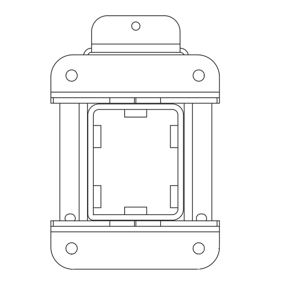
Mounting the detector directly
Fit the back-box of the detector onto the wall
by inserting the three M6 bolts, studs or
screws into the mounting holes.
PREFERRED METHOD
Fig. 1: Detector Orientation Relative to Horizon
Mounting the detector using the
bracket
A bracket (stainless steel) is available to mount
the detector that provides flexible adjustment to
easily position the detector to cover the pro-
tected area.
The surface chosen for the mounting should be
flat over the area of the mounting bracket to
ensure a stable fixing.
The FV400 Series of detectors can be operated
in any position but the mounting point must be
chosen to allow sufficient clearance for adjust-
FV400
1/20
Advertisement
Table of Contents

Related Manuals for ZETTLER FLAMEVision FV400 Series

Summary of Contents for ZETTLER FLAMEVision FV400 Series
- Page 1 Triple IR Flame Detectors FV400 FV400 Series Triple IR Flame Detectors- Fixing Instructions Introduction On the FV400 Series of detectors, all electrical connections are made via terminal blocks inside This guide describes the installation procedure the rear housing of the detector. Two 20 mm of the FV400 Series of detectors and covers all cable entries are provided.
- Page 2 FV400 Triple IR Flame Detectors ment of the angle and must also allow space for A drilling template is provided to allow optimum the cable assembly. selection of the fixing centres. A clearance of 200 mm, in all directions, from the fixing point will normally be sufficient to allow the full range of adjustment as shown in Fig.
- Page 3 Triple IR Flame Detectors FV400 FV411 RANGE : 2 x 20 mm GLAND HOLES Fig. 3: FV400 Series of Detectors-Overall Dimensions Temporary Weatherproof cover The back-box is supplied with a cover that pro- tects the wiring from the weather. CAUTION If the top-case is not fitted straight away then fit the Weatherproof cover to protect the wiring.
- Page 4 FV400 Triple IR Flame Detectors Fitting the Weather hood inside the detector using the EMC clamp. The signals from the different interfaces can be freely 1 Loosen the three detector fixings and slide the mixed together and do not need an individual detector forward.
- Page 5 Triple IR Flame Detectors FV400 Cable Entry Sealing CAUTION Cable glands and stopping plugs MUST be certified to the required standard. They must be properly sealed to prevent the ingress of moisture. Cable glands MUST be sealed to the detector housing by fitting a sealing washer between their flange and the housing.
- Page 6 FV400 Triple IR Flame Detectors Connections Terminals Description Tables 1 to 4 details the power supplies, termi- 0 V IN Detector main power input -VE nals and links for the different interfaces of the (DC/Zone/Loop) FV400 Series of detectors. 0 V OUT Detector main power -VE to next detector Reference Document...
- Page 7 Triple IR Flame Detectors FV400 Terminals Description Links Description WTEST/LED 0 V 0 V for Walk-test Input HDR1 Fit to connect 4-20 mA -VE to 0 V in and Remote Indicator Sink mode (LED) Output Fit to connect 4-20 mA +VE to HDR2 WTEST Walk-test Input...
- Page 8 FV400 Triple IR Flame Detectors Relay Mode LINKS ALARM RELAY CON4 Contact normally closed Opens in alarm Contact normally open Closes in alarm FAULT RELAY CON5 +24V Contact normally closed Opens in fault ALARM RELAY Select N/C or N/O on CON4 Contact normally open Closes in fault FAULT RELAY...
- Page 9 Triple IR Flame Detectors FV400 MX Loop LOOP -VE LOOP -VE LOOP+VE LOOP+VE Fig. 7: MX Loop Wiring Diagram Ancillary power MUST be used for RS485, Window Heater and Video, see Fig. 11. Do not fit links HDR3 or HDR4. Dotted lines show the loop connections to the next detector in the MX loop.
- Page 10 FV400 Triple IR Flame Detectors 4-20 mA Sink LINKS HDR1 Select SINK Mode +24V 4-20mA SINK Monitor current into 0V Fig. 8: 4-20mA Sink Wiring Diagram Fit link HDR1 to connect 4-20 mA- to 0 V. Ancillary power is required for RS485, Window Heater and Video. Either use the Main Detector Supply by fitting HDR3 and HDR4 or use a separate Ancillary Supply (see Fig.
- Page 11 Triple IR Flame Detectors FV400 4-20 mA Source LINKS HDR2 Select SOURCE Mode +24V 4-20mA SOURCE Monitor current drawn from Line (+24V) Supply Fig. 9: 4-20mA Source Wiring Diagram Fit link HDR2 to connect 4-20 mA+ to 24 V. Ancillary power is required for RS485, Window Heater and Video. Either use the Main Detector Supply by fitting HDR3 and HDR4 or use a separate Ancillary Supply (see Fig.
- Page 12 FV400 Triple IR Flame Detectors Conventional Zone ZONE- ZONE- ZONE+ ZONE+ Fig. 10: Conventional Zone Wiring Diagram Zone end of line (EOL) resistor fitted in last detector. Otherwise connect to next detector as shown. If the Window Heater is required, then the Ancillary power MUST be used. DO NOT FIT HDR3 OR HDR4.
- Page 13 Triple IR Flame Detectors FV400 Ancillary Power LINKS HDR3 HDR4 Fit HDR3 and HDR4 to use the Main Supply to provide Ancillary Power. Do not fit HDR3 and HDR4 in the MX Loop or Conventional Zone interfaces. +24V Fig. 11: Ancillary Power Wiring Diagram The Ancillary Power is required for the Window heater, RS485 and Camera/Video options.
- Page 14 FV400 Triple IR Flame Detectors RS485 and Video Resistor RS485+ RS485+ RS485- RS485- VIDEO To PASSIVE ACTIVE Balun Fig. 12: RS485 and Video Wiring Diagram EOL Termination resistor (100R) to be fitted at each end of RS485 bus. Dotted lines show the connections to the next detector on the RS485 network. If this is the last detector in the network, then fit the EOL resistor as shown.
- Page 15 Triple IR Flame Detectors FV400 Walk-Test Input and LED REMOTE 1.8K FAULT ALARM WINDOW RESET TEST TEST TEST Fig. 13: Walk-Test Input and Remote LED Wiring Diagram Do not use Ancillary 0 V for Wired Input and Remote LED. LED drive current limited to 3 mA. LED voltage should be less than 3 V.
- Page 16 FV400 Triple IR Flame Detectors Switch and Header Settings The FV400 Series of detectors are very flexible and can be configured for a wide range of appli- cations. For ease of installation the most com- mon, basic options are available on DIP switches located on the back of the detector.
- Page 17 Triple IR Flame Detectors FV400 Switch2 Function Action OFF (Default) SW2-1 Window Heater SW2-2 OPM Mode Automatic Manual SW2-3 Interface See Table 8 SW2-4 Interface See Table 8 4-20 mA Modes Band mode (Discrete) Continuous (Variable) mode SW2-5 MX Mode Consys Options DIP Switch Options 4-20 mA Modes...
- Page 18 FV400 Triple IR Flame Detectors Interface Mode 4-20 mA Relay MODBUS Conventional 4 - 20 mA Current Loop and Relay (Default) Conventional 4-20 mA ...
- Page 19 Triple IR Flame Detectors FV400 Commissioning Note Programming via IR mode of the System Checks 850EMT is not supported by the FV400 WARNING Series of detectors. The Self-Test generates an alarm For information on 850EMT, refer to the that is reported on all the latest version of the 850EMT User man- interfaces.
- Page 20 FV400 Triple IR Flame Detectors © Thorn Security Ltd., Dunhams Lane, Letchworth, SG6 1BE, UK 120.515.124_FV-D-400-F, doc. version 2, 14. October 2013 Subject to change without notice.
Need help?
Do you have a question about the FLAMEVision FV400 Series and is the answer not in the manual?
Questions and answers