
Related Manuals for Helena Laboratories Actalyke XL

Summary of Contents for Helena Laboratories Actalyke XL
- Page 1 ® Actalyke Activated Clotting Time Test System Operator’s Manual Catalog Number 5770, 110-220 VAC, 50-60 Hz...
- Page 2 ® Actalyke Activated Clotting Time Test System Operator’s Manual...
- Page 3 THREE AND FOUR. Actalyke XL Program License Agreement This copy of the Actalyke XL program is sold on the condition that the purchaser agrees to the terms of this license agreement. If not, the purchaser should return the unopened diskette package to Helena Laboratories to obtain a refund.
-
Page 4: Table Of Contents
ACTALYKE XL Table of Contents List of Sections Section 1 - Instrument Use and Function................1-1 Section 2 - Principles of Operation..................2-1 Section 3 - Precautions and Limitations ................3-1 Section 4 - Hazards .......................4-1 Section 5 - Installation Instruction..................5-1 5.1. Unpacking and Inspection ....................5-1 5.2. - Page 5 ACTALYKE XL Table of Contents 6.4. Archive........................6-14 6.4.1. Save Parameters ....................6-14 6.4.2. Restore Parameters .....................6-15 6.4.3. Print Setup Parameters ..................6-15 6.4.4. Save Operator IDs ....................6-18 6.4.5. Restore Operator IDs ...................6-18 6.4.6. Print Operator ID List ...................6-19 6.5. Maintenance .......................6-19 Section 7 - Operating Instructions..................7-1 7.1.
- Page 6 Figure 5-1. Actalyke XL, front view..................5-3 Figure 5-2. Actalyke XL, rear view..................5-3 Figure 5-3. Actalyke XL, top view ...................5-4 Figure 5-4. Actalyke XL, top view with paper .................5-4 Figure 5-5. Actalyke XL, left side view..................5-5 Figure 5-6. Actalyke XL, left side view..................5-5 Figure 5-7.
- Page 7 ACTALYKE XL Table of Contents Figure 6-17. Select Operator ID Time-out Screen..............6-24 Figure 6-18. General Parameters Screen ................6-24 Figure 6-19. Enter Operator ID List Screen* ................6-24 Figure 6-20. Passwords Screen*..................6-24 Figure 6-21. Select Editable Demographics Screen.............6-25 Figure 6-22. Setup Test Parameters Screen................6-25 Figure 6-23.
-
Page 8: Section 1 - Instrument Use And Function
Bibliography ACTALYKE XL is intended for in-vitro diagnostic use only, and is for use in a laboratory or point-of-care environment. The ACTALYKE XL System can be used whenever and wherever ACT testing is desired, such as: •Hemostasis Laboratory •Cardiopulmonary Bypass Surgery •Hemodialysis... -
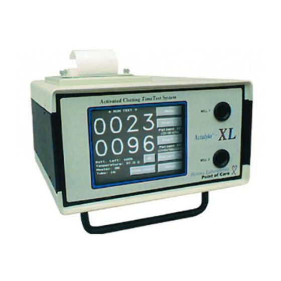
Page 9: Figure 1-1. Actalyke Xl
ACTALYKE XL ONE - Instrument Use and Function Figure 1-1. ACTALYKE XL... -
Page 10: Section 2 - Principles Of Operation
ACTALYKE XL TWO - Principles of Operation Section 2 - Principles of Operation Operation is controlled by a microprocessor, its program and memory, and a touch screen liquid-crystal display (LCD) controlling selections. The computer runs a self-test at power On to detect error conditions or potential problems. -
Page 11: Figure 2-1. Block Diagram
ACTALYKE XL TWO - Principles of Operation External Devices Barcode Keyboard Wand Floppy Drive Computer LCD Display Touch Screen Motor Temperature Printer Sensors 0° Hall Sensors Alarm Controller 90° Hall Sensors Heater Driver Test Tube Heaters Barcode Readers PCB Power Supply... -
Page 12: Section 3 - Precautions And Limitations
ACTALYKE XL THREE - Precautions and Limitations 3.12. If resistance is encountered when Section 3 - Precautions and Limitations inserting a tube into the test well, or there is 3.1. The entire Operator’s Manual should be resistance when the tube is rotating, do not read and understood before attempting force the test tube into the test well. - Page 13 ACTALYKE XL THREE - Precautions and Limitations 3.18. The ACT test results may be affected 3.24. Storage and transport environmental hemodilution, hypothermia, pharma- requirements: cologic compounds various Operating Temperature range: 15° to 30° C Storage and shipping temperatures: -20° to 45° C coagulopathies.
-
Page 14: Section 4 - Hazards
ACTALYKE XL FOUR - Hazards 4.12. WARNING: External equipment Section 4 - Hazards (barcode reader, keyboard, computer) that is 4.1. If the instrument is used in a manner connected to the instrument must have no not specified by this manual, protection live parts that are accessible. -
Page 15: Section 5 - Installation Instruction
3. Confirm the instrument is Off (Figure 5-3). signs of damage. If damage is found, notify The one connector, accessible from the rear the shipping carrier and Helena Laboratories. (Figure 5-2), is an IEC connector. Plug the 5. Inventory all items. -
Page 16: Verification Of Functionality
5.3. Verification of Functionality Read the entire Operator’s Manual. With the instrument turned On, complete the applica- ble section of the Actalyke XL Installation Report as the following steps are performed: 1. Verify Operating Environment Temperature falls within the specified range. -
Page 17: Figure 5-1. Actalyke Xl, Front View
ACTALYKE XL FIVE - Installation Instructions Display Test Wells Carrying Handle / Stand Figure 5-1. Actalyke XL, front view Fuses IEC / Power Cord Connection Figure 5-2. Actalyke XL, rear view... -
Page 18: Figure 5-3. Actalyke Xl, Top View
ACTALYKE XL FIVE - Installation Instructions Serrated Plate Adjustment Adjustment Screws Screws Paper Out Paper In Power Switch Figure 5-3. Actalyke XL, top view Paper Retainer Figure 5-4. Actalyke XL, top view with paper... -
Page 19: Figure 5-5. Actalyke Xl, Left Side View
The instrument’s left side will resemble either Figure 5-5 or 5-6. Keyboard or Barcode Reader Connection External Computer (LIS) Serial Connection Figure 5-5. Actalyke XL, left side view Keyboard or Barcode Reader Connection External Computer (LIS) Serial Connection Figure 5-6. Actalyke XL, left side view... -
Page 20: Figure 5-7. Actalyke Xl, Right Side View
ACTALYKE XL FIVE - Installation Instructions ½ ” Floppy Disk Drive Figure 5-7. Actalyke XL, right side view... -
Page 21: Section 6 - Setup
ACTALYKE XL SIX - Setup simply press OK. With no Operation Only Section 6 - Setup IDs setup, accessing the instrument in this 1. An external keyboard and barcode reader manner allows the user to have Operation may be used for portions of the instrument Only access. -
Page 22: Date Format
ACTALYKE XL SIX - Setup 5. On the Set Date screen (Figure 6-8), use 6.1.2.1. Date Format the keypad, the < key (to move the cursor to The date can be displayed in several different the left), and the > key (to move the cursor to formats. -
Page 23: Sound
ACTALYKE XL SIX - Setup 9. Select Exit to return to the Setup Time & 2. Select Interface Parameters (Figure 6-3). Date screen (Figure 6-6). 3. Select Backlight (Figure 6-4). 10. Select one of the following: 4. On the Set Backlight screen (Figure 6-11), a. -
Page 24: Contrast
ACTALYKE XL SIX - Setup 6.1.5.1. Contrast 6.1.5.2. Header/Footer The contrast of the paper and text on the The printout may contain a header and/or a printouts can be altered to aid in reading footer. To enter a header and/or a footer, an printouts. -
Page 25: Export Parameters
ACTALYKE XL SIX - Setup a. For patient tests, patient ID must be in a. For patient tests, patient ID must be in use for data to be exported (section 6.2.2). use for data to be saved (section 6.2.2). The minimum data exported is: the The minimum data saved is: the type of test run;... -
Page 26: System Timers
ACTALYKE XL SIX - Setup below Line Termination String. Note that if 1. Select Setup (Figure 6-2). carriage return is selected, <CR> appears in 2. Select Interface Parameters (Figure 6-3). the box, and, if linefeed is selected, <LF> 3. Select System Timers (Figure 6-4). -
Page 27: General Parameters
ACTALYKE XL SIX - Setup interval of 1 minute to 30 minutes, in demographics; however, cannot alter the one-minute increments. instrument setup or delete QC data. 6. To save selections, return to the Run Test b. Setup Access allows the same access... -
Page 28: Delete Operator Id/Passwords
ACTALYKE XL SIX - Setup 8. The screen displays, “Operation Only d. To save selections, return to the Run Test screen (Figure 6-2) by selecting OK Setup Access Supervisor Full Rights.” Select the appropriate access level. until the Run Test screen appears. -
Page 29: Patient
ACTALYKE XL SIX - Setup a. To enter or edit operator IDs, pass- before, during or after the test, is at the user’s words, and/or access levels, discretion. If the information is not entered section 6.2.1.1 step 4. before running a test, once the test is started, the instrument prompts the user that patient b. -
Page 30: Test
ACTALYKE XL SIX - Setup b. The ACT Timing Sequence screen 6.2.3. Test (Figure 6-23) displays. The instrument can be setup to allow a different operator ID for well 2, to prompt c. Use the keypad, Bksp (backspace) and when a specified amount of time has elapsed... -
Page 31: Qc (Bio)
ACTALYKE XL SIX - Setup c. To save selections, return to the Run 6.2.4. QC (Bio) Test screen (Figure 6-2) by selecting OK The instrument can be setup to require until the Run Test screen appears. If any certain levels of biological QC tests pass... -
Page 32: C-Act, K-Act, G-Act, And Max-Act
ACTALYKE XL SIX - Setup c. To save selections, return to the Run 9. On the Enter Lower Limit screen (Figure Test screen (Figure 6-2) by selecting OK 6-30), use the keypad, Bksp (backspace), until the Run Test screen appears. -
Page 33: Ect Levels Which Must Pass
ACTALYKE XL SIX - Setup 2. Select General Parameters (Figure 6-3). 6.2.5.1. ECT Levels Which Must Pass 3. Select ECT (Figure 6-18). If desired, the instrument can require that 4. On the Setup ECT screen (Figure 6-31), certain ECT levels pass before patient tests select Set ECT Schedule. -
Page 34: Paper Feed
ACTALYKE XL SIX - Setup Select Simple to have all test re- e. Save QC (spreadsheet) - select Yes to sults automatically print once a test is have the QC results containing all data per complete. For patient data, if Patient ID lot-to-date automatically saved on a 3½”... -
Page 35: Restore Parameters
Yes. tion plus the instrument’s currently entered settings for each parameter prints. 5. The parameters are saved and the Save/Restore/Print screen displays. Actalyke XL Parameters ================== 6. To return to the Run Test screen (Figure Version Instrument S/N:... - Page 36 ACTALYKE XL SIX - Setup lotnum: Actalyke XL Parameter ECT: =================== MAX-ACT: Version: (printout will list current software G-ACT: K-ACT: version information) C-ACT: Instrument S/N (instrument serial number): serial_number: (printout will list the pre-programmed qc_forced: ect_forced: instrument serial number) qc_sched:...
- Page 37 ACTALYKE XL SIX - Setup QC PARAMETERS (section 6.2.4 and 6.2.5) range_lo (QC Mean and Range Lower well_lvl (well level): (printout will list the Limit): current level for each test well) ECT: 90, 290, 490 0 (1), 1 (2) or 2 (3)
-
Page 38: Save Operator Ids
ACTALYKE XL SIX - Setup qc_sched (Set QC Schedule): (printout will linterm (Spreadsheet Parameters Line list the entered time interval in hours) Termination String): x0 x0 x0 x0 x0 ect_sched (ECT Schedule): (printout will list [Up to five line terminators may be the entered time interval in hours) selected. -
Page 39: Print Operator Id List
ACTALYKE XL SIX - Setup 1. Select Setup (Figure 6-2). 2. Select Archive (Figure 6-3). 3. From screen Save/Restore/Print (Figure 6-34), select Restore Operator IDs. 4. The instrument prompts to notify that the instrument's file will be overwritten. proceed, select Yes. -
Page 40: Figure 6-1. Enter Operator Id Screen
ACTALYKE XL SIX - Setup * Enter Operator ID* *Setup* Bksp Clear General Interface Parameters Parameters Operator ID 0123 Archive Maintenance Password **** Paper Feed Must return to main screen for changes to be saved Figure 6-1. Enter Operator ID Screen* Figure 6-3. -
Page 41: Figure 6-5. Select Preferred Keypad Screen
ACTALYKE XL SIX - Setup *Select Preferred Keypad* *Set Date Format* dd/mm/yy dd/mm/yyyy yy/mm/dd yyyy/mm/dd mm/dd/yy mm/dd/yyyy MMM dd, yyyy Phone Calculator Figure 6-5. Select Preferred Keypad Figure 6-7. Set Date Format Screen Screen *Setup Time & Date* *Set Date*... -
Page 42: Figure 6-9. Set Time Screen
ACTALYKE XL SIX - Setup *Set Time* *Set Backlight* Current Time Select Backlight Brightness Level 09:01:00 AM Full on New Time < > 09:01:00 AM 12/24 Hr AM/PM Set Time Exit Figure 6-9. Set Time Screen* Figure 6-11. Set Backlight Screen... -
Page 43: Figure 6-13. Printer Contrast Adjustment Screen
ACTALYKE XL SIX - Setup *Printer Contrast Adjustment* *Set Spreadsheet Parameters* Item Separation Character (Column Delimiter) Line Carriage Contrast: 10 Termination Return Linefeed String <CR> <LF> Other line termination characters may be added via an external keyboard Clear Undo Include column labels Figure 6-15. -
Page 44: Figure 6-17. Select Operator Id Time-Out Screen
ACTALYKE XL SIX - Setup Access Level of the currently indicated Operator ID: 0 (no level assigned), 1 (Operation Only), 2 (Setup Access), 3 (Supervisor Full Rights) *Select operator ID time-out* *Enter Operator ID List* New Operator ID Access When the instrument has remained... -
Page 45: Figure 6-21. Select Editable Demographics Screen
ACTALYKE XL SIX - Setup *ACT Timing Sequence* *Select Editable Demographics* Bksp Clear Patient ID Always Immediate Entry Perform ACT every ID Auto Entry Interval (Hrs) minutes Height Weight Figure 6-21. Select Editable Figure 6-23. ACT Timing Sequence Demographics Screen... -
Page 46: Figure 6-25. Setup Qc Screen
ACTALYKE XL SIX - Setup *QC Lot Numbers* *Setup QC* QC levels which Test: C-ACT must pass: Level Lot Number Set QC Schedule Enter Parameters for: C-Act K-Act G-Act Max-Act Figure 6-25. Setup QC Screen Figure 6-27. QC Lot Numbers Screen... -
Page 47: Figure 6-29. Qc Mean And Range Screen
ACTALYKE XL SIX - Setup *Setup ECT* *QC Mean and Range* Test: C-ACT ECT levels which must pass: Upper Lower Level Mean Limit Limit Set ECT Schedule Figure 6-29. QC Mean and Range Screen Figure 6-31. Setup ECT screen or Upper... -
Page 48: Figure 6-33. Setup Automatic Output Screen
ACTALYKE XL SIX - Setup *Setup Automatic Output* Make Selections for Automatic: View Chart-------------- Print ---------------------- None Simple Chart Transmit----------------- Save Patient----------- (spreadsheet) Save QC---------------- (spreadsheet) Figure 6-33. Setup Automatic Output Screen *Save/Restore/Print* Save Save Operator Parameters Restore Restore Parameters... -
Page 49: Section 7 - Operating Instructions
ACTALYKE XL SEVEN - Operating Instructions 4. If saving data for use on a spreadsheet, Section 7 - Operating Instructions insert a floppy disk into the disk drive (see 1. If transmitting data to an external com- Figure 5-7 for disk drive location). - Page 50 ACTALYKE XL SEVEN - Operating Instructions 1. Confirm the instrument is ready for use by the tube clockwise to ensure the tube is fully observing that the Run Test screen is inserted. If Out remains, see section 10.2. displayed and that the test well temperatures 9.
-
Page 51: Patient Id/Patient Demographics
ACTALYKE XL SEVEN - Operating Instructions clotting time results, the prompt to run the c. To delete any test data for the currently required ACT and/or QC test will not appear displayed patient ID, see section 7.1.2.1.6 until the timer(s) are reset to zero.) step 2. -
Page 52: Sex
ACTALYKE XL SEVEN - Operating Instructions To alter the demographics, select 1. Select Patient ID and the Patient Demo- OK to exit the screen and see step 2 of graphics screen (Figure 7-3) displays. section 7.1.2.1.3, 7.1.2.1.4, and/or 7.1.2.1.5. 2. To select the applicable sex for the 4. -
Page 53: Weight
ACTALYKE XL SEVEN - Operating Instructions 5. With the correct height indicated, press 6. With the selected weight displayed in the Current Weight field, select from OK. Select. 6. With the selected height displayed in the 7. From the Patient Demographics screen Current Height field, select OK. -
Page 54: Heparin Dosage Documentation
ACTALYKE XL SEVEN - Operating Instructions e. To return to the Run Test screen, b. To enter/select a patient ID and/or test select OK. type, see section 7.1.2.1.2 step 2. c. To select a demographic, sex, height, 7.1.2.1.7. Heparin Dosage and/or weight, see step 2 of section 7.1.2.1.3,... -
Page 55: Change Operator
ACTALYKE XL SEVEN - Operating Instructions floppy disk. To access the charted data, use a. To enter the ID assigned to well 1, this the following steps beginning from the Run ID will determine the access level for both Test screen (Figure 7-2): users, select Main and see step 3. -
Page 56: Battery
ACTALYKE XL SEVEN - Operating Instructions clotting time quality control verification in After the pre-selected time interval of section 8.1.1. non-use has elapsed (section 6.1.8.1), the instrument powers down. If further validation of the system is required, several tests should be run using Actalyke... -
Page 57: Operator Id
If data files were retained, enter the the instrument displays, "Remove disk from appropriate Operator ID and Password and drive A:, reboot, and see Actalyke XL Opera- select OK. tor's Manual Software Installation section for further instruction." Press the button located b. -
Page 58: Figure 7-1. Enter Operator Id Screen*
ACTALYKE XL SEVEN - Operating Instructions If the Allow 2nd Operator for Well 2 feature is in use and Change Operator Once a Patient ID Number of ACT points and then Well 2 are selected, then this is is entered, the ID attributed to the patient and the Enter Well 2 Operator ID screen. -
Page 59: Figure 7-5. Select Patient Height Screen
ACTALYKE XL SEVEN - Operating Instructions *Select Patient Height* *Heparin Dosage* Bksp Clear 0.0m - 0' 0" Current Height 0.1m - 0' 3" 0.2m - 0' 7" 0.0m - 0' 0" Select Enter Dosage 0.3m - 0' 11" 0.4m - 1' 3"... -
Page 60: Figure 7-9. Results Act Chart Printout
ACTALYKE XL SEVEN - Operating Instructions Description of printed information To include/exclude from printout, see section a) Header 6.1.5.2 b) Printout title always included c) Patient ID 6.2.2 & 7.1.2.1 d) Test always included e) Operator ID 6.1.5 f) Clot time results charted always included (6.2.6 &... -
Page 61: Section 8 - Test Functions And Quality Control
ACTALYKE XL EIGHT - Test Functions and Quality Control a. Select Cancel and then OK to return to Section 8 - Test Functions and Quality the Run Test screen (Figure 8-1). Control Routine quality control testing and tracking b. Select Well #1 or Well #2 for the de- should be part of a comprehensive quality sired test well and proceed to step 4. -
Page 62: View/Output View Chart (Levey-Jennings Chart)
ACTALYKE XL EIGHT - Test Functions and Quality Control procedure. Biological QC tests should then 6. QC tests can be run on both wells simul- be performed at least weekly to verify system taneously, so if a test and a level need to be function. -
Page 63: Delete Complete Qc Test Data
ACTALYKE XL EIGHT - Test Functions and Quality Control 3. The Levey-Jennings Chart (Figure 8-4) 4. The instrument displays, “All QC clotting displays the tests results for the test type times for all levels of the selected test will be currently selected for well 1. -
Page 64: Temperature Qc (Test Well Temperature Check)
ACTALYKE XL EIGHT - Test Functions and Quality Control 8. If no data exists for a test, well, and level, 5. The temperature should remain in a range an error message displays. Touch the of 36.5 to 37.5°C. If the temperature screen to remove the prompt and press Test, exceeds this range, see section 10.2. -
Page 65: Figure 8-1. Run Test (Qc Mode) Screen
ACTALYKE XL EIGHT - Test Functions and Quality Control or ECT Sched:, which ever has the least time ECT for ECT QC or QC remaining. Time shown for Biological QC. in hours, minutes, and 1, 2 or 3 depending on Indicates test type in use. -
Page 66: Figure 8-5. Levey-Jennings Chart Printout
ACTALYKE XL EIGHT - Test Functions and Quality Control Description of printed information a) Header b) Printout Title c) Test d) Well number e) Level Lot numbers g) Mean h) Standard Deviation Quantity of tests run for each level QC result time charted... -
Page 67: Section 9 - Performance Specifications
Length - 100 mm External Diameter - 13 mm Correlation Data Material: Borosilicate glass or plastic The Actalyke XL and the MINI were com- Style: Round Bottom or Flat Bottom pared to the Actalyke using MAX-ACT tubes. Label: (for operator identification and tracking) The data was as follows: Test Type: Activator type. -
Page 68: C-Act, K-Act And G-Act
II. The coefficient of variation for each test Actalyke XL type was less than 10%. The precision of the MAX-ACT tubes with the C-ACT K-ACT G-ACT Actalyke XL ACT system was evaluated by Level performing multiple replicates on twenty mean 127.0 388.2 125.1 389.9 146.8... - Page 69 15.8 Instrument / Tube % cv A-A* = Actalyke / Actalyke M-A* = MINI / Actalyke XL-A* = Actalyke XL / Actalyke Accuracy Data H-H = Hemochron / Hemochron H-A = Hemochron / Actalyke The accuracy of the Actalyke Activated...
-
Page 70: Section 10 - Maintenance, Troubleshooting, Warranty
For instrument turning On the power switch. calibration or for maintenance not described in this manual, call Helena Laboratories for 10.1.2. Clotting Time Check assistance. The Actalyke Electronic Clotting Tube (ECT), Catalog Number XL-ECT, is available for... -
Page 71: Test Well Temperature Check
ACTALYKE XL TEN - Maintenance, Troubleshooting, Warranty contains time results when the time interval with a commercial virucidal and germicidal between QC/ECT tests elapses, the prompt agent. Using a lint-free tissue and a cotton to run the next QC/ECT test will not display. -
Page 72: Mag Sensor Calibration
If the calibration was successful, the power. If the fuse immediately blows again, Maintenance screen displays (see step 8). call Helena Laboratories for assistance. b. If the calibration failed, an error mes- sage displays. Record the error message, 10.1.7. Mag Sensor Calibration... -
Page 73: Battery Replacement
The bracket is secured with two kep 10.1.9. Battery Replacement nuts and two standoffs. Use the wrench to To replace the battery, use the Actalyke XL remove the kep nuts and nut driver to Battery Pack,... -
Page 74: Touch Panel Calibration
ACTALYKE XL TEN - Maintenance, Troubleshooting, Warranty 7. Place the bracket over the battery, by 14. Dispose of the spent battery in accor- aligning the holes in the bracket with the dance with local, state, federal corresponding screws coming from the right regulations. -
Page 75: Figure 10-1. Battery Replacement
ACTALYKE XL TEN - Maintenance, Troubleshooting, Warranty 1. Use the lid key on the TOP slot 2. Use the lid key on the BOTTOM slot 3. BATTERY CONNECTOR 4. STANDOFFS 5. BATTERY CABLE 6. KEP NUTS 7. BRACKET 8. BATTERY 9. -
Page 76: Figure 10-2. Preventive Maintenance Schedule Checklist
ACTALYKE XL TEN - Maintenance, Troubleshooting, Warranty Figure 10-2. Preventive Maintenance schedule Checklist 10-7... -
Page 77: Troubleshooting
ACTALYKE XL TEN - Maintenance, Troubleshooting, Warranty 10.2. Troubleshooting If the unit appears to be malfunctioning for any reason, thoroughly check for physical damage to the case, indicators, etc. caused by dropping or excessive mishandling. Should instrument problems be suspected, it is recommended that several tests be run using Actalyke Quality Control material and whichever test tubes are used clinically. - Page 78 Incorrect test type and/or level Repeat test. selected New lot of QC test in use and Enter new range limits (section range limits not updated 6.2.4.3) and repeat test. Faulty tube Repeat test. If remains out of range, call Helena Laboratories. 10-9...
- Page 79 ACTALYKE XL TEN - Maintenance, Troubleshooting, Warranty Symptom Possible Cause(s) Action Required No power to instrument Power cord unplugged and Plug cord into wall outlet and turn insufficient charge in battery On to use and charge battery. Battery charge depleted (power...
- Page 80 External computer (LIS) communica- Verify LIS status. establish communication. Aborting tion problems. transfer, touch screen to continue. Instrument communication problems. Call Helena Laboratories. (ASTM protocol in use) If instrument on battery power, Rerun test. Warning - Temperature out of range heaters not back up to temperature in well X.
-
Page 81: Warranty
This warranty is provided to the original purchaser for one year from date of sale. Particular Exclusions Unauthorized modification of any part of the Actalyke XL instrument will void this War- ranty. 10.4. Regulatory Information The Actalyke XL System conforms to the... -
Page 82: Section 11 - Symbology
ACTALYKE XL ELEVEN - Symbology Section 11 - Symbology NOTE: The following symbols may be used in this manual, or on the instrument, to provide information necessary to the user, if applicable. Caution, electric shock hazard, high voltages capable of causing personal... -
Page 83: Section 12 - Communication Specifications
Establishment, Transfer, ring indicator and Terminate. *only these lines are used by the Actalyke XL Establishment Phase software. The Establishment phase determines the direction of information flow and prepares the COMMUNICATIONS PROTOCOL: receiver to accept information. - Page 84 "0" to "7". The frame number begins at an <ENQ>, the data link is in contention. "1" with the first frame of the transfer phase. The Actalyke XL has priority to transmit The frame number is incremented by one for information...
- Page 85 If the sender chooses DATA TRANSFER FORMAT to ignore the <EOT>, the receiver must retransmit the request. The Actalyke XL software in general adheres to the ASTM Standard Specification for Termination Phase Transferring Information Between Clinical The termination phase returns the data link Instruments and Computer System.
- Page 86 (i-1) delimit- Order Record ers. Delimiters are not included for trailing The Actalyke XL will transmit an order record null fields; that is, if the tenth field was the immediately preceding any results records...
- Page 87 (yyyymmddhhmmss). The date is transmitted with the year first, month second and day last. date/time completed - Date and time the test finished The Actalyke XL does not recognize result records transmitted by the computer system. EXAMPLE: For patient result record: R|1|^^^G-ACT|139|sec||||F|||2002050314380...
-
Page 88: Section 13 - Menu Flowchart
ACTALYKE XL THIRTEEN - Menu Flowchart Section 13 - Menu Flowchart 13-1... - Page 89 ACTALYKE XL THIRTEEN - Menu Flowchart 13-2...
- Page 90 ACTALYKE XL THIRTEEN - Menu Flowchart 13-3...
- Page 91 ACTALYKE XL THIRTEEN - Menu Flowchart 13-4...
- Page 92 ACTALYKE XL THIRTEEN - Menu Flowchart 13-5...
-
Page 93: Section 14 - Index
Actalyke Thermometer, 5-1, Date Format, 6-2, 6-18, 8-4, 10-2 Heparin, 6-9, 7-6, 7-11 6-21 Storage Capacity, 7-2 Actalyke XL Battery Pack, Delete, 7-4, 8-3, 8-4 Heparin Dosage, 7-6 5-1, 10-4 Delete Complete QC Test Additional Materials, 5-1 High/Low Limits, 6-10, 6-27... - Page 94 ACTALYKE XL FOURTEEN - Index LIS, 5-1, 6-4, 6-9, 6-14, 7-1, Print, 6-13, 6-16, 7-7, 8-2, Save Parameters, 6-14, 7-7, 8-3 6-15 Lot Numbers, 6-12, 6-17, Print Operator ID List, 6-19 Save Patient (spreadsheet), 6-26, 8-2 Print Setup Parameters, 6-14, 7-7 Lower/Upper.
- Page 95 ACTALYKE XL FOURTEEN - Index Verification of Functionality, View Chart, 6-13, 6-16, 7-6, 7-7, 8-2 View/Output, 8-2 Warranty, 10-1, 10-12 Weight, 6-9, 6-16, 7-5, 7-11, Well 2 Operator ID. See Allow 2nd Operator for Well 2 XON-XOFF, 12-1 14-3...
- Page 96 ® Actalyke Operator's Manual For additional information, call Helena Laboratories at 800-231-5663, toll free. Helena Laboratories Helena Laboratories UK, Ltd P.O. Box 752 Colima Avenue Beaumont, Texas 77704-0752 Sunderland Enterprise Park Sunderland SR5 3XB England © January, 2007 D6500093L Helena Laboratories, Inc.
Need help?
Do you have a question about the Actalyke XL and is the answer not in the manual?
Questions and answers