Table of Contents

Related Manuals for Stromag HGE Series

Summary of Contents for Stromag HGE Series
- Page 1 Gear limit switch Type series HGE Document No.: 152-00000 F Date: 10/2017 EKM-0119 Stromag GmbH Hansastraße 120 D-59425 Unna Mounting/operating instructions Tel.: +49 (0) 2303 102-0 Fax: +49 (0) 2303 102-201 www.stromag.com EN-GB info@stromag.com...
-
Page 2: Table Of Contents
Contents Introduction..........................1 About this documentation........................... 1 1.1.1 Target group............................1 1.1.2 Use/storage............................. 1 Using the documentation correctly......................2 1.2.1 Text formats.............................2 1.2.2 Definition of terms............................2 Warranty and liability..........................3 1.3.1 Guarantee..............................3 1.3.2 Copyright..............................3 For your safety...........................3 Safety concept of the documentation......................3 Required personnel qualifications.......................4 Intended use............................... - Page 3 4.1.6 Type code..............................17 Dimensional drawing..........................18 Marking on the product..........................18 Construction and function......................19 Switch sizes.............................. 19 Component designations.......................... 20 Design, task and function of the assembly groups................... 20 5.3.1 Electrical connections..........................21 5.3.2 Mounting position...........................21 5.3.3 Drive flange............................22 Optional equipment available........................22 5.4.1 Design with additional potentiometer.....................22 5.4.2...
- Page 4 8.4.1 Cleaning..............................39 Troubleshooting........................39 Operational issues and their solutions......................39 Disassembly..........................39 10.1 Special safety guidelines.......................... 39 10.2 Removing the GTES..........................39 10.3 Final decommissioning..........................39 Ordering spare parts....................... 40 11.1 Data for ordering spare parts........................40 11.2 Service address............................40 EC Declaration of Conformity....................41 Mounting/operating instructions Gear limit switch Type series HGE •...
-
Page 5: Introduction
A dimensional drawing is supplied as a separate document and can be requested additionally from Stromag Customer Care, see section 4.2. For this, the information on ordering spare parts is required, see section 11.1. -
Page 6: Using The Documentation Correctly
Trained personnel Trained personnel include persons who can prove they have been trained by Stromag or in accordance with the technical documentation provided by Stromag. They are able to carry out the work assigned to them and avoid known dangers. -
Page 7: Warranty And Liability
Warranty and liability The "General trade and delivery terms and conditions of delivery" of Stromag always apply. Stromag shall not recognise any warranty or liability claims for personal and material damage if they result from one or more of the following causes: •... -
Page 8: Required Personnel Qualifications
Required personnel qualifications The following table shows the qualifications specified for the different tasks. Task Personnel Transport Trained personnel Assembly Qualified personnel Initial commissioning Qualified personnel Operation Qualified personnel Preventive maintenance Qualified personnel Troubleshooting Qualified personnel Decommissioning Qualified personnel Disassembly, disposal Trained personnel •... -
Page 9: Standards Applied
2.5.1 Standards applied An overview of the applied harmonised standards can be found in the EC Declaration of Conformity supplied. Possible residual risks Residual risks are particular dangers that cannot be eliminated when using the GTES, despite its safety-orienta- ted construction. Residual risks are not obviously recognisable and could be the source of a possible injury or health risk. -
Page 10: Mandatory Symbols
CAUTION Indicates a possible medium risk danger, which can lead to death or serious physical injury if not avoi- ded. ATTENTION Indicates a possible low risk danger, which can lead to slight or medium physical injury or material damage if not avoided. 2.7.3 Mandatory symbols Basic protection... -
Page 11: Safety Symbols/Pictograms On The Gtes
• Never make changes, additions or conversions to the GTES without the manufacturer's approval. If any changes are made to the GTES that impair safety, they must be reported to Stromag immediately. • Only use genuine spare parts. 2.12 Safe handling of rotating components The following safety guidelines must always be observed when handling rotating components. -
Page 12: 2.14.1 Responsibility Of The Operator
The GTES has been constructed and marketed in compliance with relevant legal harmonisation regulations. It is the operator's responsibility to ensure that EMC regulations for the machine are observed. For any further questions or additional support required, please contact Stromag Customer Care. 2.15 Environmental protection The following instructions must always be observed in order to protect the environment. -
Page 13: Transport And Storage
Transport and storage Transport NOTE Be particularly careful when transporting the GTES in order to avoid damage caused by external forces or careless loading and unloading. Depending on the type and duration of the transportation, corresponding transportation locks have been provided. Remove the transport lock only when begin- ning assembly, see section 6.3. -
Page 14: Storage
► Maximum relative humidity, 60 %. For storage periods longer than 12 months, the general condition of all parts and the packing must be checked regularly. Stromag’s Customer Care can provide you with information on this, please refer to section 11.2 for the address. - Page 15 Gearbox - Table 1 for contacts 80, 81, 88, 90, 90G with cam discs 40° FV70 Contact Contact 88 Contact Contact Contact 88 80, 90, 80/81 90, 90G 10,67 1,333 0,073 0,097 3,638 1,819 0,364 0,20 0,371 18,29 2,286 0,125 0,166 6,236 3,118...
- Page 16 Gearbox - Table 1 for contacts 51 with cam discs 40° FV70 Gearbox - Table 1 for contacts 52, 53 with cam discs 40° FV50 Cont- Cont- Cont- Contact 51, Contact 51, act 53 10,35 1,650 0,097 0,085 5,093 0,20 0,256 17,74 2,829...
-
Page 17: General Information
4.1.3 General information - independent from the size of the housing Information Value Comment Operating time 100 % Suitable for continuous operation Radial force drive max. 200 N Maximum permissible shear force F Axial force max. 300 N Maximum permissible axial load of the shaft Ambient temperature -40°C to +85°C -30°C to +85°C (for contact 51, 52, 53) - Page 18 EKM-0114 Fig. 2 51: Circuit changeover with twin break 54: Circuit breaker switch electrically isolated contact bridges 52: Circuit changeover quick action with 1, 2, 3, 4, Connection points twin break contact bridges electrically iso- 13, 14, lated from each other 21, 22 53: Circuit changeover button with twin break contact bridges electrically isolated...
- Page 19 Alternating current AC Contact Con- Switc Con- Func Electrical data Operat- Temper- tact hing nection tion ing life ature materi- sys- -30°C … ● ● ● ● +85°C 30x10 ● ● ● ● ● -25°C … 2.5A 250V +80°C ● ●...
-
Page 20: Contact Positions
The required dimensions and weights in kg can be obtained from the respective GTES dimensional drawing. This can be requested as a separate document from Stromag’s Customer Care department. Mounting/operating instructions Gear limit switch Type series HGE • No. 152-00000 F • 10/2017... -
Page 21: Type Code
4.1.6 Type code 155_HGE_590_BFV_50_A1R EKM-0128 Fig. 3 Example: 155 HGE 5 90 B F V 50 A1R Nominal revolutions, see section 4.1.2. Switch type Number of fitted contacts Type of fitted contacts, see section 4.1.4. Block adjustment (only for cam discs Ø 70 mm) Doubled (fine adjustment) Fine adjustment Adjustability of the switching points... -
Page 22: Dimensional Drawing
Dimensional drawing NOTE Stromag would like to emphasise that users should refer to the dimensional drawing for all technical details, including: dimensions, weights, tolerances, tightening torques, and any other technical specifi- cations and units required for assembly, such as securing equipment and lubricants. -
Page 23: Construction And Function
Construction and function Switch sizes EKM-0127 Fig. 4 Switch size A1R Switch size A1R Switch size A1L The switch sizes shown in the figure above present a selection. The overview of all switch sizes can be obtained from the type code explanation, see section 4.1.6. Mounting/operating instructions Gear limit switch Type series HGE •... -
Page 24: Component Designations
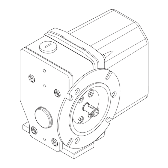
Component designations EKM-0120 Fig. 5 Housing with gear part Flange Contacts Drive shaft, design with parallel key Cam disc Cam disc group The component designations of the GTES are given here as an example with switch size A1R. Design, task and function of the assembly groups The limit switch consists of a gear part and one or two switch parts (design A or design B), which are firmly fitted to each other. -
Page 25: Electrical Connections
5.3.1 Electrical connections All contact connectors can be found within the switch housing. The earth conductor for grounding the housing can be found on the bearing plate. The electrical connections for contact connectors and earth conductors occur via screw connections. The bores for cable entry points are closed with blind plugs for delivery of the switch. The bores can be found in the gearbox housing. -
Page 26: Drive Flange
5.3.3 Drive flange As far as is possible, the drive should occur free of shear force through the drive flange type F or type F+M that is suitable for the switch, see section 6.2.4. 23.5 3 Nm (+/- 0,5 Nm) 3.04 - 0.01 11.8... -
Page 27: Adjustment Of The Potentiometer With Drive Via A Torsionally-Stiff Coupling
5.4.2 Adjustment of the potentiometer with drive via a torsionally-stiff coupling EKM-0093 Fig. 7 Clamping nut Potentiometer Servo clamps According to the design, the potentiometer (7) is fastened to a support plate (3) with a clamping nut (4) or with servo clamps (5). -
Page 28: Design With Heating Resistor
Proceed as follows when using a drive over gear wheels for adjustment of the potentiometer: Adjusting the po- 1. Loosen the clamp bolt (1). tentiometer 2. With the switching shaft stationary: Turn the gear wheel. 3. Screw the clamp bolt (1) in tightly. 5.4.4 Design with heating resistor The GTES can optionally be provided with heating. -
Page 29: Assembly
Assembly Special safety guidelines CAUTION Risk of accidents caused by live components For all work on components or individual parts, the machine must be switched off and secured against non-intended reconnection. ► Check that the machine is de-energised before beginning the work. CAUTION Risk of accidents caused by rotating components Risk of entanglement in the area between the GTES and the machine due to rotating components. -
Page 30: Tightening Torques
6.2.3 Tightening torques Unless otherwise specified, the screws should be tightened according to the tightening torques provided in the DIN. Machine and adjacent construction fixing elements must be tightened according to the manufacturer's instruc- tions. Location/connection Tightening torque [Nm] Comment Flange on the machine housing See section 6.3 et seq. -
Page 31: Assembly Of The Housing (Design With Flange)
2. Depending on the installation conditions: Mount the GTES on the housing using screws, see the follow- ing table. Housing Unless oth- side erwise specified in the operat- ing instruc- tions of the machine: 10 Nm 3. Adjust the switching points, see section 6.6. 4. -
Page 32: Insert The Connection Cable Into The Gtes
6.4.1 Insert the connection cable into the GTES Insertion of the 1. Insert the machine-side connection cable via the ca- connection cable ble entry point (1) in the switch housing. NOTE The cable screws used must correspond to at least the protection class of the housing used, see section 2.14.3. -
Page 33: Connect The Earth Conductor
2. Connect the heating via a 2-pole terminal block. 3. If no further connections are to be made: close and screw in the cover directly. Tightening torques, see section 6.2.3. 6.4.4 Connect the earth conductor Earth conductor An earth conductor of up to 1,5 mm (min. - Page 34 NOTE The cam discs are designed so that a constant nominal travel and castor run are available. No dam- age is caused when the castor run is exceeded. The contact readopts the previous switching position. Preparations CAUTION Risk of accidents caused by live components There are live components in the area of the electrical connections.
-
Page 35: Normal Adjustment "V50
6.6.1 Normal adjustment "V50" EKM-0096 Fig. 16 Two cam discs are arranged for each contact, which are continuously adjustable. According to the position of the cam, the castor run can be doubled for a contact and the nominal travel shortened accordingly. The effective cam angle (5) and the usable angle of the cam disc (6) are illustrated in the figure. -
Page 36: Fine Adjustment "Fv50
6.6.2 Fine adjustment “FV50” EKM-0097 Fig. 17 Each contact is assigned to a cam disc group, consisting of an adjustable cam (6) and cam disc (7). The adjust- able cam (6) is connected via positive locking over a ring with toothing on both sides (2) to the switching shaft. While the worm’s (8) self-locking feature is enabled, the torque is transferred further by means of positive lock- ing from the adjustable cam (6) to the toothing of the cam disc (7). -
Page 37: Double Fine Adjustment "Dfv
6.6.3 Double fine adjustment "DFV" EKM-0098 Fig. 18 Two cam disc groups are assigned to each contact, consisting of adjustable cams (6) and cam discs (7). Each cam disc pair can be adjusted infinitely and used in a defined way from both sides. The effective cam angle (10) and the usable angle of the cam disc (11) are shown in the figure. -
Page 38: Normal Adjustment "V70
6.6.4 Normal adjustment "V70" EKM-0099 Fig. 19 Two cam discs are arranged for each contact, which are continuously adjustable. The cam discs (1) can be adjusted independently of one another after loosening the nut (3). The locking plate (2) as well as the inner ring (4) thereby prevent the adjustment of a previously adjusted cam disc by adjusting the next disc. -
Page 39: Block Adjustment "Bv
A cam disc group is assigned to each contact, consisting of a cam disc (1), adjustable cam (2), adjustment worm (3) and tooth ring (4). The adjustable cam (2) is connected to the switching shaft by means of positive locking via a tooth ring (4). The adjustment worm (3) with a self-locking feature transfers the torque further by means of positive locking from the adjustable cam (2) to the toothing of the cam disc (1). -
Page 40: Block Adjustment "Bfv
Adjusting the NOTE complete cam A block adjustment is offered when the adjusted individual switching points should block not be altered to each other, for example, when the wire length is changed. With a block adjustment, the relative adjustment of the individual contacts to each other remains unchanged. -
Page 41: Mount The Cover
Adjusting the NOTE complete cam A block adjustment is offered when the adjusted individual switching points should block not be altered to each other, for example, when the wire length is changed. With a block adjustment, the relative adjustment of the individual contacts to each other remains unchanged. -
Page 42: Operating Conditions
7.3.1 Operating conditions See section 4.1. Recommissioning No specific measures are necessary for recommissioning. Decommissioning 7.5.1 Temporary decommissioning No specific measures are necessary for temporary decommissioning. 7.5.2 Final decommissioning No specific measures are necessary for final decommissioning. Dispose of materials according to local regulations. Maintenance and inspections Special safety guidelines CAUTION... -
Page 43: Cleaning
The seals of the cover must be replaced as necessary after repeated opening of the cover. Troubleshooting Operational issues and their solutions No typical GTES malfunctions are known, should you have any queries regarding adjustment or commissioning, please contact Stromag’s Customer Care department, see section 11.2. 10 Disassembly 10.1 Special safety guidelines CAUTION Risk of accidents due to non-observance of the safety guidelines There is a risk of accidents if the general safety guidelines are not observed. -
Page 44: Ordering Spare Parts
Stromag or by spare parts that have not been replaced properly. Please bear in mind that special manufac- turing and delivery specifications often apply to our own as well as to foreign parts and that we always offer spare parts according to the latest technical specifications and current legal regulations. -
Page 45: Ec Declaration Of Conformity
12 EC Declaration of Conformity Mounting/operating instructions Gear limit switch Type series HGE • No. 152-00000 F • 10/2017... - Page 46 Mounting/operating instructions Gear limit switch Type series HGE • No. 152-00000 F • 10/2017...
- Page 47 Mounting/operating instructions Gear limit switch Type series HGE • No. 152-00000 F • 10/2017...
- Page 48 Stromag GmbH Hansastraße 120 D-59425 Unna Tel.: +49 (0) 2303 102-0 Fax: +49 (0) 2303 102-201 www.stromag.com info@stromag.com...
Need help?
Do you have a question about the HGE Series and is the answer not in the manual?
Questions and answers