Table of Contents
Advertisement
Advertisement
Table of Contents

Summary of Contents for GPI Flomec RT14
-
Page 1: Instruction Manual
RT14 Flow Rate Totaliser Instruction Manual Version 21.16... -
Page 2: General Information
General Information This manual provides the necessary information for installation and operation of your flow instrument; for detailed information on any flowmeters or accessories supplied with your instrument please consult the relevant flowmeter product manual. This instrument should only be installed and maintained by persons familiar with local regulations, particularly those for workplace Health and Safety. -
Page 3: Table Of Contents
Table of Contents Introduction ....................4 Product Overview.....................4 Specifications ....................5 Operation ....................... 6 LCD Display ......................6 Keypad Function ....................7 Operating Functions ..................8 Mechanical Installation ................13 General Requirements ...................13 Conduit Entries ....................13 Integral Meter Mounting ................13 Wall and Pipe Mounting ................14 Panel Mounting ...................14 Electrical Installation .................. -
Page 4: Introduction
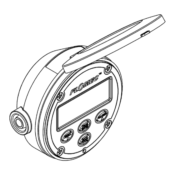
1. Introduction 1.1 Product Overview The RT14 Rate Totaliser is designed for computing, displaying and transmitting totals and flowrates from a flowmeter with a pulse or frequency output. The instrument will display Flow Rate, Total and Accumulated Total in engineering units as programmed by the user. Simple flow chart programming with scrolling English prompts guides you through the programming routine greatly reducing the need to refer to the instruction manual. -
Page 5: Specifications
1.2 Specifications High impact glass reinforced Nylon (PA6) with a Polycarbonate lens, Nitrile O-Ring Physical seals and Polyurethane gaskets, providing an IP rating of IP66/67 Operating Temperature Range is -30 C ~ +80 C (-22 F ~ +176 8 digit alpha-numeric LCD display with 12mm characters Display: Display backlight available with external DC power Total units are selectable for litres, millilitres, gallons, cubic metres, quarts,... -
Page 6: Operation
2. Operation 2.1 LCD Display Upon entering the programming mode the LCD will conduct a display test where all LCD segments are displayed for 3 seconds Rate display is indicated by the RATE flag in the bottom row of the display. 8 digits are available for Rate display, user selectable for up to 3 decimal places. -
Page 7: Keypad Function
2.2 Keypad Function FUNCTION IN OPERATING MODE FUNCTION IN PROGRAM MODE Press and hold for 3 seconds to Selects the digit to be reset the Total display to zero. incremented/edited, moves the Total must be displayed on LCD curser to the right. display to reset it Each press progresses to the next Press and hold to display the... -
Page 8: Operating Functions
2.3 Operating Functions 2.3.1 Resettable Total The display toggles between Rate and Total displays when the RATE/TOTAL key is pressed. Pressing the RESET key and holding for a period of 3 seconds while the Total is displayed on the LCD will cause the Total to reset to zero. 2.3.2 Accumulated Total The Accumulated Total is displayed momentarily whenever the ACC.TOTAL key is pressed, holding the key will hold the Accumulated Total display. - Page 9 2.3.4 Display Backlight The display backlight will be automatically enabled upon connection of an external DC voltage supply in the range of 12-30V; the backlight is not available when operating on battery or loop power. If it is required to reduce power consumption while operating on external DC power the backlight can be overridden in the Advanced Menu (see section 5.10).
- Page 10 2.3.7 Scaled Pulse Output The Scaled Pulse Output is used to transmit the totalised volume at a user selectable resolution; this is programmed as a volume quantity per output pulse (e.g. 10Litres/Pulse or 100mL/Pulse). The frequency of the Scaled Pulse Output signal automatically adjusts according to the input frequency and the scale factor, up to a maximum limit of 100Hz.
- Page 11 The passive NPN output will function on battery power, however this will reduce the battery life of the instrument by approximately 50%. For applications requiring an alarm output which is not triggered often the effect on battery life is expected to be negligible. Internal protection is provided for voltage spikes caused by switching inductive loads (relays, solenoids, etc.) by fitment of an internal flyback (suppressor) diode to the passive NPN output.
- Page 12 A low battery is indicated by the battery symbol on the lower line of the LCD display; illumination of this indicator shows that the battery should be replaced as soon as possible. Generally the remaining battery life after low battery indication is several days however this is not guaranteed.
-
Page 13: Mechanical Installation
3. Mechanical Installation 3.1 General Requirements Installation of this product should only be carried out by suitably qualified/trained personnel with an understanding of local regulations regarding electrical installations, and if relevant Hazardous Area electrical installations. It is recommended that the instrument is installed in a location where it is shielded from extreme varying weather conditions, and from chances of physical impact. -
Page 14: Wall And Pipe Mounting
3.4 Wall and Pipe Mounting 42.6 mm ( 1.67 ” ) Mounting of the instrument on a pipe or flat surface (such as a wall) can be accomplished using the ‘Wall Mount Kit’, or ‘Pipe Mount Kit’ available from the manufacturer. -
Page 15: Electrical Installation
4. Electrical Installation All wiring connections should be made with good quality shielded instrument cable; wiring between terminals which are inside the instrument enclosure, or between a flowmeter and an integrally mounted instrument may use non-shielded wire. Cable shields or drain wires should be connected to the instrument ground (GND) at the instrument end only –... -
Page 16: Input Connections
4.2 Input Connections The input type must be set in the software before the below wiring connections will function 4.2.1 Reed Switch Input 4.2.2 NPN Sensor Input (Hall Effect) - Page 17 4.2.3 PNP Sensor Input 4.2.4 Voltage Pulse Input (Wiegand Sensor / DP Meters)
-
Page 18: Output Connections
4.2.5 VR Coil Input (Turbine Meters) 4.3 Output Connections 4.3.1 Passive NPN Digital Output with Unpowered Sensor Notes: Shown here with Reed Switch input, Coil and Voltage Pulse inputs also suitable for this configuration. *External 12-30V DC power supply to instrument is optional. - Page 19 4.3.2 Passive NPN Digital Output with Powered Sensor 4.3.3 PNP Digital Output – configuration suitable for all input types...
- Page 20 4.3.4 Digital Output to a Relay – Recommended connection for all 12-30V DC Relays Note: Wiring connection from voltage supply to +24V terminal on instrument is not compulsory, however it will prolong battery life. 4.3.5 Digital Output to a Relay – For up to 50V DC and 50V AC Relays Note: This output type is not internally protected from voltage spikes from inductive loads, a diode must be fitted as shown for DC loads, or a Metal Oxide Varistor fitted for AC circuits.
- Page 21 4.3.6 Analogue Output with an Unpowered Sensor – Negative Reference Notes: Shown here with Reed Switch input, Coil and Voltage Pulse inputs also suitable for this configuration. 4.3.7 Analogue Output with an Unpowered Sensor – Positive Reference Notes: Shown here with Reed Switch input, Coil and Voltage Pulse inputs also suitable for this configuration.
- Page 22 4.3.8 Analogue Output with a Powered Sensor – Negative Reference 4.3.9 Analogue Output with a Powered Sensor – Positive Reference Note: Some instrumentation systems may have a common ground between the analogue input and the DC supply, for those systems this wiring configuration will not be possible and configuration 4.3.8 must be used.
-
Page 23: Connections For Combined Outputs
4.4 Connections for Combined Outputs 4.4.1 Combined Analogue Output and NPN Digital Output to Common Receiver 4.4.2 Combined Analogue Output and PNP Digital Output to Common Receiver... -
Page 24: Programming Parameters
5. Programming Parameters 5.1 PIN Program Protection Any user defined PIN other than 0000 will engage the program protection mode; after the PIN protection mode is enabled failure to input the correct PIN number will deny the user the ability to change any of the program parameters, but will allow read only access to the user so that they may view existing program settings. -
Page 25: Decimal Places
5.4 Decimal Places Decimal places are separately adjustable for Total, Accumulated Total, and Rate from zero to three decimal places. The decimal places setting for Rate will set the available decimal places in the analogue output set point. The decimal place settings for Total and Accumulated Total do not influence configuration of the pulse output. -
Page 26: Digital Output
Non-linearity correction functions as an intermediate process between the receiving of input pulses and the calculation of totals; therefore all subsequent processes such as Rate calculation, analogue output calculations, and pulses/alarm outputs are also corrected according to the settings programmed for the non-linearity correction. The non-linearity correction function is programmed using up to 10 frequency points, and a K-factor for each frequency point. -
Page 27: Analogue Output
output the signal at the maximum of 100Hz, and all excess pulses will be stored in memory until such a time that flow has stopped and the instrument can output the stored pulses – it is not recommended that systems be designed to operate in this way under normal conditions. The output frequency can be calculated as follows: ����������������... -
Page 28: Advanced Menu
5.10 Advanced Menu 5.10.1 Resetting Accumulated Total Resetting the accumulated total can only be done at this level of the Advanced Menu; by PIN protecting the instrument it is possible to remove the ability of an operator to reset the accumulated total. - Page 29 However it should be kept in mind that for any battery powered applications, using a value lower than the default will decrease battery life. 5.10.5 Analogue Output Adjustment The analogue output may be adjusted/trimmed at this level of the program; this should not be necessary in most applications as the analogue output is factory calibrated, however it may be useful when operating at extreme ambient temperatures.
-
Page 30: Programming Flowchart
6. Programming Flowchart... -
Page 33: Program Detail Record
7. Program Detail Record User PIN Total Engineering Units Rate Rate Conversion Factor RCF = Time Base for Rate /Sec /Min /Day Total 0.00 0.000 Decimal Accum. Total 0.00 0.000 Points Rate 0.00 0.000 K-Factor (pulses / unit) Input Type Reed Coil Non Linearity Correction... -
Page 34: Spare Parts
8. Spare Parts Spare parts for your instrument are available from the local dealer or national distributor from whom you purchased the instrument; see spare parts list below to determine which parts numbers you require. Description: Includes: Part No: Bezel Cover 1 x Bezel Cover 1306014 Complete replacement front housing with clear... - Page 35 Notes:...
-
Page 36: Manufacturer's Declaration
9. Manufacturer’s Declaration We, Trimec Industries Pty Ltd, of Sydney Australia, trading as Great Plains Industries Australia or ‘FLOMEC’ Declare under our sole responsibility that the RT14 Rate Totaliser is in conformance with the following European directives: 2014/30/EU EMC Directive Conformity is declared under the following standards EN61000-6-2:2005 Electromagnetic compatibility (EMC).Generic standards.
Need help?
Do you have a question about the Flomec RT14 and is the answer not in the manual?
Questions and answers