
Related Manuals for Axminster Craft AC250CM

Summary of Contents for Axminster Craft AC250CM
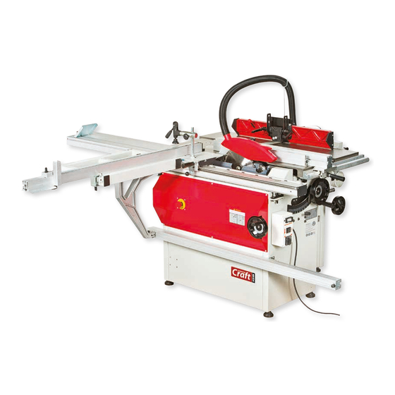
- Page 1 Code 105104 Original Instructions AC250CM 250mm DeLuxe Combination Machine AT&M: 22/06/2018 BOOK REF: 105171...
-
Page 2: Eu Declaration Of Conformity
EN 60204-1: 2006+A1+AC EN 61000-3-2: 2006+A1+A2 EN 940: 2006+A1 Combination Machine Type EN 61000-3-11: 2000 AC250CM Model conforms to the machinery example for which the EC Type-Examination Certificate No BM50314354, AN50176407, AN50217062 has been issued by Laizhou Planet Machinery Co., Ltd Signed at: Yutai West Street, Laizhou, Shandong 261400 China and complies with the relevant essential health and safety requirements. -
Page 3: What's Included
What’s Included Model Number: AC250CM Panel Saw: 250mm DeLuxe Combination Machine Rip Fence Assembly 250mm Saw Blade Saw Guard Flexible rubber Hose with Support Rod Adjustable Work Clamp Assembly Depth Stop Bracket Sliding Table Guide Rail Sliding Table Guide Rail Stops... -
Page 4: General Instructions For 230V Machines
General Instructions for 230V Machines • Carry out a final check e.g. check the cutting tool The following will enable you to observe good working practices, keep yourself and fellow workers safe and is securely tightened in the machine and the correct maintain your tools and equipment in good working speed and function set. -
Page 5: Specific Safety Precautions
Specific Safety Precautions Panel Saw Make sure the saw blade is the correct type for the job in Do not attempt to carry out cross cutting operations hand. ‘freehand’ , always use the mitre fence for small material and the sliding carriage for larger work pieces. Unless you Do not force the saw, if the saw begins to ‘stall’... - Page 6 Specific Safety Precautions In addition to the safety requirements contained in these Planer/Thicknesser Operating Instructions and your country’s applicable Most machines currently are well interlocked to ensure regulations, you should observe the generally recognized that the machine must be in the correct configuration to technical rules concerning the operation of woodworking perform one task or the other.
-
Page 7: Specification
Periodically, clean any excess build up of resin from the thicknessing table, and apply any proprietary brand of lubricating agent. Specification Code 105104 Model AC250CM Power 3,000W (Saw) 2,000W ( Planer) 3,000W (Spindle) 230V Number of Motors Blade Speed 4,050rpm Blade Tilt 0 - 45°... -
Page 8: Assembly Instructions
Assembly Instructions PLEASE NOTE: Some of this assembly Fig 01 procedure is best accomplished by two persons. Although the tasks are not impossible, some of the items are heavy and awkward, and a mishandling error could cause injury. Please think about what you are doing, your capabilities and your personal safety. - Page 9 Assembly Instructions 2) Locate the steel pin plate (A) , line up the pins with the MAKE SURE THE SUPPORT CASTING WHEEL elongated slots in the extension table (B) and lower the RUNS SMOOTHLY ALONG THE EXTENSION RAIL! plate into the table, see fig 4. Locate the two lift and shift Fig 04 5) On top of the extension table there are two adjustment caphead screws, using a straight edge adjust the screws...
- Page 10 Assembly Instructions two pre-drilled holes on top of the extension table, see Fig 13 fig 10. Lift-up the 90˚ stop located to the corners of the extension table, push the fence up against the 90˚ stop, see fig 11 and clamp the angle bracket (A) to the table’s steel girder by tightening the butterfly knob, see fig 12.
- Page 11 Assembly Instructions Fig16 Fig 19 Flexible hose End cover Fig 17 Fig 20-21 Flexible hose M8X50 Bolt ‘T’ Slot Dust extraction outlet Fig 18 4) Replace the cover to the end of the guide rail (C) and secure with the Phillips screws you removed earlier. Position the rail so it lines up with the edge of the saw table and only finger tighten the nuts at this point, see fig 22.
- Page 12 Assembly Instructions 5) Locate the rip fence (A) and lower the clamp assembly Rip-Fence Extension over the guide rail (C), see fig 23. 1) Locate the rip fence extension (B) and the two ‘T’ bolts, washers and clamping knobs. Slide the ‘T’ bolts into the ‘T’ Fig 23- 24 slot to the end of the fence extension casting, see fig 27.
- Page 13 Assembly Instructions 3) Raise the saw blade to it’s highest point and slide the Mount the overhand plane guard arm onto the side of fence assembly (A) up against the blade and adjust the the out feed table that corresponds to your preferred fence guide rail (C) until the pointer reads ‘0’on the scale handing, then fit the overhand cutter block guard.
- Page 14 Assembly Instructions Spindle Moulder WARNING!! DISCONNECT THE MACHINE FROM THE MAINS BEFORE CONTINUING! NOTE: IN ORDER TO INSTALL THE SPINDLE MOULDER ASSEMBLY THE FOLLOWING COMPONENTS NEED TO BE REMOVED. 1) Remove the panel saw rip fence by lifting the locking 2) Lift the spindle guard assembly onto the work table, lever up and lifting the fence away from the guide rail, manoeuvre the assembly over the pre-drilled holes in the...
-
Page 15: Positioning The Machine
Assembly Instructions 4) Place a 90˚degrees square against the fence and adjust Fig 42-43 the assembly until the fence is perpendicular to the table, tighten the clamping handles to lock the guard in place, see fig 40. Fig 40 Fence M8 Cap head bolts Square Lifting point hole... -
Page 16: Machine Dimensions
Positioning the Machine Fig 45 3) Manoeuvre the machine to the chosen location making sure there is sufficient space all round, then carefully lower the machine down, see fig 45. 4) With the machine in position lower the rear feet by loosening the two “raise and lowering bolts”... -
Page 17: Machine Foot Print
Machine Foot Print Sliding Table 2020mm Sliding Table 1920mm... -
Page 18: Illustration And Parts Description
Illustration and Parts Description Spindle Moulder Set Up Panel Saw Set Up... - Page 19 Illustration and Parts Description Planer Set Up Thicknesser Set Up...
- Page 20 Illustration and Parts Description Flexible hose ‘Y’ support rod Saw guard Saw table Rip fence Sliding table Table extension fence 3 Way control switch assembly Guide rail Main emergency stop Tilt control hand wheel Planer out feed table Spindle moulder assembly Saw table Fence assembly Distance stop...
- Page 21 Illustration and Parts Description Guide roller height clamping knob Guide arm clamp Guide arm Anti-kickback clamping knob Clamping knob Guide roller height Anti-kickback clamping knob height clamping knob Fence adjusting knob Anti-kickback assembly Fence advancing knob Guide roller Fence advancing assembly clamping knob NVR On/Off switch...
- Page 22 Illustration and Parts Description Work clamp Cutter block guard adjuster Height adjuster knob Mounting arm lock Fence rail Fence Spindle moulder rise/fall Out feed table control handle wheel adjuster Thicknessing table rise and fall control Cutter block guard Cutter block guard clamp Spindle moulder access door ON/OFF Switch Planer/...
- Page 23 Illustration and Parts Description Cam lock (A), Table height Feed scale overhand (A) Feed table locking handle (A) locating bolts (B) to level the table Pointer (B) with the cutter block blade Sliding table height assembly (A) Saw table height adjusters (A) Autofeed engage control (A) Planer/Thicknesser ON/OFF switch (A) Panel saw rise and fall control...
- Page 24 Illustration and Parts Description Fence securing clamp (A), Fence mounting bracket (B), Planer fence base (C), Elongated fence support bracket (D), Fence locking handle (E), Fence positioning knob lever (F), Fence adjusting bolt (G), Spindle moulder circular rings (H) Rip fence locking handle (A), Rip fence micro adjuster (B), Magnifying glass (C), Fence rail scale (D), Fence rail rack (E)
- Page 25 Illustration and Parts Description Magnifying glass Riving knife (A), Saw blade (B), Scoring blade (C) Distance stop assembly Butterfly clamp Telescopic extension assembly 90˚ degree extension fence stop Main emergency stop button Spindle moulder motor assembly (A) and motor door micro switch (B)
-
Page 26: Setting Up The Machine
Setting Up the Machine the angle scale reading is correct. Set the rip fence a WARNING!! DISCONNECT THE MACHINE FROM predetermined distance from the saw blade and lock in THE MAINS BEFORE CONTINUING! position. Check that the rip fence is held securely when it is locked in position. - Page 27 Setting Up the Machine blade is sitting just proud of the table, see fig 50. Connect the machine to the mains supply, press the power selector switch to the ‘I’ position for spindle moulder/panel saw, turn the selector switch to ‘2’ panel Fig 50 saw (see page 21) and give the machine a quick burst.
- Page 28 Setting Up the Machine Unsuitable, incorrectly mounted, dull, cracked or bent Close up the aluminium fences to give approximately cutter knives can break or increase the risk of kickback 5mm clearance around the cutter, see diagram below. considerably. The installation of sanding or polishing tools is not Spindle permissible.
- Page 29 Operating Instructions Fig 53 Power On Procedure: 1) Rotate the selector switch (A) in the vertical position. 2) Press the selector switch (B) to select the planer/thick- Green button nesser icon (I). 3) Press the NVR ON/OFF switch (C) to the “ON” position, then press one of the green “ON"...
- Page 30 Operating Instructions Correct Operating Position Fig 55 Position yourself offset to the machine as shown above Work Piece Handling • Feed the work piece straight across the machine table, holding the fingers close together and guiding the work piece with the palms of your hands. •...
- Page 31 Operating Instructions 6) • Check that the room is well lit. Planer/Thicknesser Blades • Make sure that the saw table is clear of any tools. WARNING!! DISCONNECT THE MACHINE FROM THE MAINS BEFORE CONTINUING! • Check that the saw guard is against the top of the board.
- Page 32 Operating Instructions from the slot and lay them aside. Repeat the process for the other two blades. If the block becomes difficult to hold located, being out of balance with the blade/s removed; use a thin wedge of material to jam the cutter block in position.
- Page 33 Operating Instructions Fig 63 Changing the Panel Saw Blade Riving knife WARNING!! DISCONNECT THE MACHINE FROM THE MAINS BEFORE CONTINUING! Raise the saw blade to it’s highest point. Remove the saw blade guard. Pull the sliding table locking knob towards you and slide the table to the side to expose the blades.
- Page 34 Operating Instructions Changing the Spindle Moulder Cutter WARNING!! DISCONNECT THE MACHINE FROM THE MAINS BEFORE CONTINUING! WARNING!! DISCONNECT THE MACHINE FROM THE MAINS BEFORE CONTINUING! Changing the Spindle Moulder Speed Open the spindle moulder access door to the side of the Raise the spindle to the maximum height by unlocking machine, see fig 66.
- Page 35 Operating Instructions/Routine Maintenance Close the access door, raise the spindle, reconnect the height of the table lock stud. Hold the stud firmly and machine to the mains supply. Give the machine a ‘quick’ loosen the lock nut, adjust the stud, lightly ‘pinch’ with burst check ( i.e.
- Page 36 Exploded Diagrams/Lists Planer Thicknessser Assembly...
- Page 37 Exploded Diagrams/Lists...
- Page 38 Exploded Diagrams/Lists...
- Page 39 Exploded Diagrams/Lists Planer Thicknessser Assembly Dust chute head Sprocket I DESCRIPTION Locking plate Sprocket II Right and left Change-over plate Iron friction wheel Support plate Screw M5x6 Sprocket III Plate Thicknessing table Tension plate Right plate assembly Spring Bearing tube Lifting tube Guiding fence Support base...
- Page 40 Exploded Diagrams/Lists Hand wheel Socket cap screw Socket cap screw M8x30 M6x12 Nut M10 Screw M8x8 Hex bolt WI5x50 Screw M5x8 Screw M6x10 Screw ST5x40 Screw M5x8 Socket cap screw Nut MS Hex bolt M8x16 M6x35 Nut MS Hex nut M8 Screw M4x6 Hex bolt M8x16 Washer ɸ...
- Page 41 Exploded Diagrams/Lists Panel Saw/ Planer Thicknesser Assembly DESCRIPTION SAW BENCH AND MILLING BODY PLANER THICKNESSER BODY FRONT CONNECTED PLATE BACK CONNECTED PLATE CAP SCREW M8X20 SPRING WASHER 8 FLAT WASHER 8 CAP SCREW M8X20 SPRING WASHER 8 FLAT WASHER 8...
- Page 42 Exploded Diagrams/Lists Panel Saw/ Spindle Moulder Assembly...
- Page 43 Exploded Diagrams/Lists Cap screw M5x10 DESCRIPTION Flat washer 5 Saw bench and moulder body Cap screw M6x45 Saw bench and moulder table Hex nut M6 Phillips screw M10X70 Steel foot Hex nut MIO Hex nut MIO Flat washer MO Support pole Double saw blade assembly Hex nut M16 Locking block...
- Page 44 Exploded Diagrams/Lists Panel Saw Assembly 1...
- Page 45 Exploded Diagrams/Lists Cap screw M6x30 DESCRIPTION Hex nut M6 Small blade stand Flat washer 6 Phillips screw M6X10 Adjusting plate Big axle Phillips screw M8X30 Adjusting washer Cap screw M5x10 Round Nut M20x1.5 Adjusting axle Hex bolt M10x25 (left) “C” ring 12 Washer 10 Little axle Big outer plate...
- Page 46 Exploded Diagrams/Lists Panel Saw Assembly 2...
- Page 47 Exploded Diagrams/Lists Cap screw M5x12 Hex locking nut DESCRIPTION Lifting pole Lock handle Combined belt Key A4X12 Washer 8 1.5x25x750 Hex locking nut M8 Turning handle Flower bolt M8X( at Flat washer 12 Key A5X10 least)130 Flat washer 8 Flat washer 16 Adjusting spring Exchange block Connected plate...
- Page 48 Exploded Diagrams/Lists Panel Saw Assembly 3 Support block DESCRIPTION Hex thin nut M12 Screw M5x12 Locking handle Hand wheel washer Cap screw M8x16 Hand wheel ɸ12x ɸ125 Flat washer 8 Small clamp plate Location stand Cap screw M6x12 Stand block Flat washer 6 Location pole Worm gear axle...
- Page 49 Exploded Diagrams/Lists Spindle Moulder Assembly Continues Over..
- Page 50 Exploded Diagrams/Lists Spindle Moulder Assembly Washer (pulley 2) DESCRIPTION Cap screw M6x20 Spindle seat Hex screw M10x100 Hex locking nut M12 Round nut M25x1.5 Spindle Lifting thread pole Bolt M5X16 Gear Spring cover Spacer Bearing 6206-2Z/Z2 Bearing 51101 “C” ring 30 Sleeve B Spindle sleeve Small round nut M12X1.25...
- Page 51 Exploded Diagrams/Lists Extension Table Assembly DESCRIPTION Support plate Adjusting centre Bolt Knob bolt Bearing 6001 Flat washer 6 Flat washer 6 Sliding block Hex nut M6 Hex screw M6x16 Cap screw M6x20 Flat washer 6 Flat washer 6 Sliding staff Extension table (total) Cover Combined scale (total)
- Page 52 Exploded Diagrams/Lists Rip-Fence Assembly Spring Collar M5 Square Nut DESCRIPTION Locking Plate Gear Sliding Plank M4X8 Screw Collar M6 Screw Handle M6X10 Screw M6 Nut Washer Washer Locking Block End Cap Horizontal Staff Shaft M4X10 Screw Horizontal Staff Cap Fine adjusting Slide Fence M4X10 Screw Handle...
- Page 53 Exploded Diagrams/Lists Work Clamp Assembly DESCRIPTION Cap screw M6X12 Knob bolt Washer 6 Horizontal bar Nut M6 Clamp sleeve Guide plate Knob (M8) Front location block Cap screw M5X12 Back location block Washer 6 Phillips screw M6X12 Nut M5 Hex nut M6 Scale Hex bolt M6X30 Knob screw M6X8...
-
Page 54: Wiring Diagram
Wiring Diagram... - Page 55 Cutter Block Accessories Axcaliber Shear Cutting Axcaliber 45deg Rebate Cutter Head Lock Mitre Cutter Head Axcaliber Euro Cutter Head Euro lock mitre cutter head bits are ideal for milling Two sizes of limiter cutter block, 78mm and 100mm, mitre joints in max 29mm stock. The quick and both with 30mm bores, which designed to accept easy way to accurately create boxes, stretcher bars, the range of Euro cutters and limiters shown within...
- Page 56 The Axminster guarantee is available on Craft, Trade, Engineer, Air Tools & CNC Technology Series machines Buy with confidence from Axminster! So sure are we of the quality, we cover all parts and labour free of charge for three years! For more information visit axminster.co.uk/3years The packaging is suitable for recycling.
Need help?
Do you have a question about the AC250CM and is the answer not in the manual?
Questions and answers