
Related Manuals for Magnum MLT4150


Summary of Contents for Magnum MLT4150
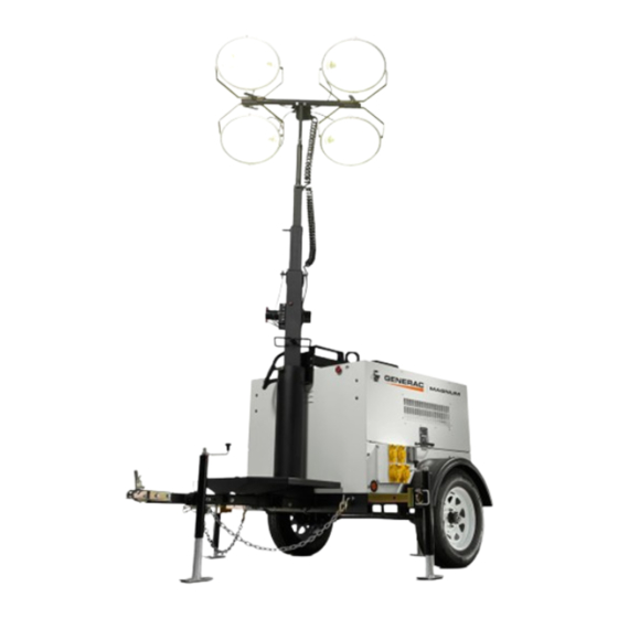
- Page 1 NIGHTBUSTER LIGHT TOWER MLT4150 • MLT4200 OPERATING/PARTS MANUAL www.discount-equipment.com...
- Page 2 We sell worldwide for the brands: Genie, Terex, JLG, MultiQuip, Mayco, Toro/Stone, Diamond Products, Magnum, Airman, Mustang, Power Blanket, Nifty Lift, Atlas Copco, Chicago Pneumatic, Allmand Brothers, Essick, Miller Spreader, Skyjack, Lull, Skytrak,...
-
Page 3: Introduction
Occupational Safety and Health Association (OSHA) guidelines. Keep a copy of this manual with the unit at all times. Additional copies are available from Magnum Products LLC. An engine operators manual was also supplied with the unit at the time of shipment from the factory. The manual provides detailed operation and maintenance procedures for the engine. -
Page 4: Table Of Contents
ENCLOSURE ASSEMBLY ..................... 32 - 33 FRAME AND COMPONENTS ....................34 - 36 ENGINE COOLING ASSEMBLY ....................37 ENGINE ASSEMBLY MITSUBISHI- MLT4150 ................. 38 - 39 ENGINE ASSEMBLY ISUZU - MLT4200 ................. 40 - 41 CONTROL PANEL ASSEMBLY ....................42 - 43 OVAL LIGHT ASSEMBLY ...................... -
Page 5: Safety Notes
SAFETY NOTES This is the safety alert symbol. It is used to alert you to potential personal injury hazards. Obey all safety messages that follow this symbol to avoid possible injury or death. This manual contains DANGERS, WARNINGS, CAUTIONS, NOTICES and NOTES which must be followed to prevent the possibility of improper service, damage to the equipment, personal injury or death. -
Page 6: Engine Safety
ENGINE SAFETY Internal combustion engines present special hazards during operation and fueling! Failure to follow the safety guidelines described below could result in severe injury or death. Also read and follow all safety warnings described in the engine operator’s manual. A copy of this manual was supplied with unit when it was shipped from the factory. -
Page 7: Towing Safety
If you believe your trailer has a defect which could cause a crash or could cause injury or death, you should immedi- ately inform the National Highway Traffic Safety Administration (NHTSA) in addition to notifying Magnum Products LLC. If NHTSA receives similar complaints, it may open an investigation; and if it finds that a safety defect exists in a group of vehicles, it may order a recall and remedy campaign. -
Page 8: Safety Symbol Summary
SAFETY SYMBOL SUMMARY This equipment has been supplied with numerous safety and operating decals. These decals provide important operating instructions and warn of dangers and hazards. Replace any missing or hard-to-read decals and use care when washing or cleaning the unit. Decal placement and part numbers can be found in the beginning of the parts section of this manual. -
Page 9: Specifications
Read all of the manuals included with this unit. Each manual details specific information regarding items such as set up, use and service requirements. SPECIFICATIONS ARE SUBJECT TO CHANGE WITHOUT NOTICE. MAGNUM MODEL MLT4150 MLT4200 Engine Make/Brand, Model .......... -
Page 10: Light Tower Set Up
LIGHT TOWER SET UP 1. For maximum light coverage locate tower at ground level or in a spot higher than the area being illuminated by the lamps. WARNING The tower extends up to 30 ft (9.14 m). Make sure area above the trailer is open and clear of overhead wires and obstructions. -
Page 11: Raising The Tower
RAISING THE TOWER WITH THE MANUAL WINCH WARNING The trailer must be leveled with the outriggers extended before raising the tower. The outriggers must remain extended while the tower is up. Failure to level the trailer or extend the outriggers will severely reduce the stability of the unit and could allow the tower to tip and fall. -
Page 12: Raising The Tower
RAISING THE TOWER WITH THE OPTIONAL ELECTRIC WINCH 1. Set up and level the trailer as described on page 9, and follow steps 1-3 on page 10. 2. Remove the safety pin from the mast lock bar (R). 3. Press the lower winch control toggle switch upward to raise mast into the vertical position (S). -
Page 13: Main Control Panel
MAIN CONTROL PANEL PRODUCTS LLC BERLIN, WI. USA 1-800-926-9768 1. MAIN CIRCUIT BREAKER (70A or 100A): This breaker will disconnect power to the lights and auxiliary outlets. 2. BALLAST INDICATOR LIGHTS: Indicates power from the ballast to each light. 3. INDIVIDUAL CIRCUIT BREAKERS: One breaker is supplied for each light. 4. -
Page 14: Engine Starting And Operation
ENGINE STARTING AND OPERATION 1. Check engine oil, fuel and coolant levels. Note: If the engine was run out of fuel or the fuel tank was drained, it may be necessary to bleed the fuel lines. Refer to the engine operation manual supplied with the unit. 2. -
Page 15: Light Operation
LIGHT OPERATION 1. Once the engine is up to temperature and running smoothly, switch main circuit breaker (1) to the ON “I” position. 2. With main circuit breaker on, switch each individual circuit breaker for the lights (2) to ON “I”, one at a time. 3. -
Page 16: Derating For Altitude
5. After the mast is completely down, insert the cradle lock pin and secure it with the safety pin. 6. Position lights to aim at the ground. If the trailer is going to be moved, Magnum Products LLC strongly recom- mends that the lights be removed from the mast and stowed for transportation. -
Page 17: Removing The Lights For Transportation
5. After the mast is completely down, insert the cradle lock pin and secure it with the safety pin. 6. Position lights to aim at the ground. If the trailer is going to be moved, Magnum Products LLC strongly recom- mends that the lights be removed from the mast and stowed for transportation. -
Page 18: Lifting The Trailer
LIFTING THE TRAILER When lifting the light tower and trailer, attach any slings, chains or hooks directly to the central lifting eye. The lifting eye is located on the mast between the two forklift pockets. Make sure the equipment being used to lift the light tower CENTRAL FORKLIFT has sufficient capacity. -
Page 19: Troubleshooting The Lights
2. Generator output incorrect. Check the incoming voltage to the ballast by checking the available voltage on the duplex receptacle. Incoming voltage should be 120V +/- 5V. If voltage is incorrect engine speed may need to be adjusted or generator may require service. Contact Magnum Products Technical Service Department for more information. -
Page 20: Engine Maintenance
ENGINE MAINTENANCE Note: During the first 50 hours of operation, avoid long periods of no load or sustained maximum load operation. If the light tower is to run for longer than five minutes without a load, shut the engine down. The engine is supplied with engine break-in oil from the factory. -
Page 21: Unit Decals
LE MÂT EN BAS ET PROTÉGÉ DANS LE BERCEAU! Electric Winches ITEM NO. PART NO. DESCRIPTION 12141 Decal set, LT eng/safety 4-lang 11275 Decal, Magnum logo w/ web - red vinyl 12262 Decal, 4000/5000 set up 4-lang (manual winch) 12880 Decal, instruction 4000/5000 4-lang (electric winch) - Page 22 ITEM NO. PART NO. DESCRIPTION 12140 Decal set, common mast 4-lang 12141 Decal set, LT eng/safety 4-lang 16488 Decal, Magnum logo w/ red stripe 12142 Decal, ground 10420 Decal set, MLT4150-4200, 5150-5200 22960 Decal, breaker 20A 23203 Decal, breaker 30A...
- Page 23 ADVERTISSEMENT WARNUNG DANGER WARNING ADVERTENCIA ADVERTISSEMENT GEFAHR PELIGRO DANGER WARNUNG ADVERTENCIA ADVERTISSEMENT WARNING WARNUNG ADVERTENCIA ADVERTISSEMENT ITEM NO. PART NO. DESCRIPTION 12140 Decal set, common mast 4-lang 12141 Decal set, LT eng/safety 4-lang 16488 Decal, Magnum logo w/ red stripe...
- Page 24 UNIT DECALS DANGER DO NOT REMOVE! GEFAHR ENTFERNEN SIE NICHT! PELIGRO NO QUITE! DANGER N'ENLEVEZ PAS ! This decal is also located on the bottom side of mast Located on inside cover of mast junction box. ITEM NO. PART NO. DESCRIPTION 12140 Decal set, common mast 4-lang...
-
Page 25: Manual Winch Mast Assembly
MANUAL WINCH MAST ASSEMBLY... - Page 26 ITEM NO. PART NO. DESCRIPTION 11954 Coil cord, mast 16600 Winch, manual 60584 Nut, .750-10 nylock G5 yellow zinc 11902B Weldment, mast tube 11649Z Weldment, t-bolt 15292 Screw, .750-10X6.500 hx hd SS 15380 Pin, cotter - .125X1.250 14262 Sheave, 3 in. 60247 Washer, flat .750 14234...
-
Page 27: Electric Winch Mast Assembly
ELECTRIC WINCH MAST ASSEMBLY... - Page 28 ITEM NO. PART NO. DESCRIPTION 11954 Coil cord 12875B Cover, winch contactor 11293 Contactor, electric winch - warn 65049 Relay, 12V 30/40A N.O. w/diode 65707 Switch, toggle - SPDT spring weatherproof 12872B Bracket, winch mounting 12874 Winch, electric - 770 lb. hoist 15380 Pin, cotter - .125X1.250 15006...
-
Page 29: Auxiliary Outlet Panel Assembly
AUXILIARY OUTLET PANEL ASSEMBLY... - Page 30 ITEM NO. PART NO. DESCRIPTION 65535 Clamp, 90° 3/4" 2 screw 12248B Weldment, outlet cover 10081 Hinge, continuous - 11.00 in. 11484B Cover, breaker 14130 Receptacle, 120V 20A GFCI 65530 Block, terminal - 2 pole lug type, 7 pos./pole 14137 Receptacle, 240V 30A twist lock 18089 Receptacle, 120/ 240V 50A twist lock...
-
Page 31: Auxiliary Outlet Panel Options
AUXILIARY OUTLET PANEL OPTIONS PART NUMBER 12399 PART NUMBER 12402 Receptacle Panel (2x5-20R, 3xL6-30R, 1x50A) Receptacle Panel (2x5-20R, 3xL6-20R, 1x50A) PART NUMBER 12400 PART NUMBER 12401 Receptacle Panel (2x5-20R, 3xL14-30R, 1x50A) Receptacle Panel (2x5-20R, 4xL14-30R) - Page 32 PART NUMBER 13893 PART NUMBER 13540 Receptacle Panel (2x5-20R, 2xTT-30R, 2x14 - 50) Receptacle Panel (2x5-20R, 1xTT-30R, 1xL6-30R, 2x50A) ITEM NO. PART NO. DESCRIPTION 14130 Receptacle, 120V 20A GFCI 14137 Receptacle, 240V 30A twist lock 18089 Receptacle, 125/250V 50A twist lock 65488 Receptacle, 240V 30A twist lock 65849...
-
Page 33: Enclosure Assembly
ENCLOSURE ASSEMBLY... - Page 34 ITEM NO. PART NO. DESCRIPTION 11381 Fender, plastic - single wall 11507W Panel, right side sheet metal 16591W Panel, door 16598 Hinge, door - .188 pin, 48.5 long 25333W Panel, back access 12195 Gasket radiator access plate 10287W Panel, rear - 4000 Isuzu 11935 Pad, rubber 2.00 x 2.00 x 1.00 12344Z...
-
Page 35: Frame And Components
FRAME AND COMPONENTS 12, 59... - Page 36 ITEM NO. PART NO. DESCRIPTION 16270 Fitting, .375MNPT to .250 FNPT straight 16271 Fitting, 90-.250NPTX.188 barb 15142 Fitting, strt-.250NPTX.312 barb 12259 Fuel pick up tube - 24.00 in. 12361B Weldment, fuel tank strap 12080 Cap, fuel tank - vented, 3.5 dia. grn diesel only 12162 Tank, fuel - 56 gallon poly 14223...
- Page 37 Axle, 2200LB 58TC 45SC (not shown) OPTIONAL FEATURES For Containment/Silent Pack: 12666B Weldment, chassis - 4000 60 gal. containment blk 60760 Valve, drain 14MM-1.5 w/nipple (MLT4150) 11952 Valve, drain 20x1.5 mm thread/barb (MLT4200) 60777 Clamp, hose - .312 fuel hose crimp style 50051 3 ft.
-
Page 38: Engine Cooling Assembly
ENGINE COOLING ASSEMBLY LOWER RADIATOR HOSE ITEM NO. PART NO. DESCRIPTION 15422 Clamp, hose - SAE 020 (.75-1.75) 11891 Hose, radiator - upper (MLT 4150 only) 15185 Hose, lower radiator (MLT 4150 only) 11767B Weldment, fan guard- lft (MLT 4150 only) 12064 Hose, top radiator (MLT 4200 only) 12356... -
Page 39: Engine Assembly Mitsubishi- Mlt4150
ENGINE ASSEMBLY MITSUBISHI - MLT4150... - Page 40 ITEM NO. PART NO. DESCRIPTION 19270 Element, air filter 16443 Assembly, air filter with bracket 16445 Bracket, air cleaner housing 60018 Screw, M10X1.25X20 hx ser flg 60316 Clamp, hose - SAE 032 (1.56-2.50) 12314 Hose, air cleaner 16684 Kit, fuel feed with fittings 11745B Bracket, fuel/air filter 11821B...
-
Page 41: Engine Assembly Isuzu - Mlt4200
ENGINE ASSEMBLY ISUZU - MLT 4200... - Page 42 ITEM NO. PART NO. DESCRIPTION 21505 Assembly, air filter 60009 Screw, M8X1.25X25 hx ser flg 12990B Bracket, air filter 60018 Screw, M10X1.25X20 hx ser flg 60316 Clamp, hose - SAE 32 60342 Nut, M8X1.25 hx SS 22320 Hose, air filter 12421B Weldment, exhaust flange, high temp 25455...
-
Page 43: Control Panel Assembly
CONTROL PANEL ASSEMBLY... - Page 44 ITEM NO. PART NO. DESCRIPTION 15085 Gauge, hourmeter 11480 Panel, control (MLT 4200) 11887 Panel, control (MLT 4150) 65429 Breaker, 100A 250V 2 pole (MLT 4200) 60736 Breaker, 70A, 250V, 2 pole (MLT 4150) 65388 Light, indicator red - w/wire 12 VDC 65325 Light, indicator green - w/wire 12 VDC 14249...
-
Page 45: Oval Light Assembly
OVAL LIGHT ASSEMBLY... -
Page 46: Oval Light Assembly
ITEM NO. PART NO. DESCRIPTION 60304 Screw, M5 x 25 pan hd phillips 60447 Nut, M5 nylock 13367 Assembly, aluminum ring 13369 Lens, glass oval 13373 Gasket, lens oval 11391 Bulb, 1000W MH short length 13399 Screw, M4 x 18 pan hd phillips 60067 Washer, #10 flat .435/.060 SS 13370... -
Page 47: Rectangular Light Assembly
RECTANGULAR LIGHT ASSEMBLY... - Page 48 Block, terminal - 2 pos, 90A, 600V 11424 Reflector, end Magnum light 11399 Reflector, wrap around - Magnum light 11423 Reflector, hole in end - Magnum light 12993Z Weldment, wing nut - Magnum light 60369 Washer, ext star lock M12 12991Z...
-
Page 49: Metal Halide Ballast Box Assembly
METAL HALIDE BALLAST BOX ASSEMBLY WARNING Do not mix metal halide and high pressure sodium ballast parts! ITEM NO. PART NO. DESCRIPTION 11079 Cover, ballast box 14679 Capacitor, metal halide 11166 Transformer, metal halide 10227 Assembly, transformer & cap set 14158 Block, terminal 11078... -
Page 50: High Pressure Sodium Ballast Box Assembly
HIGH PRESSURE SODIUM BALLAST BOX ASSEMBLY WARNING Do not mix metal halide and high pressure sodium ballast parts! ITEM NO. PART NO. DESCRIPTION 11079 Cover, ballast box 14782 Capacitor, sodium light 14783 Ignitor, sodium light 11167 Transformer, sodium light 11168 Assembly, transformer &... -
Page 51: Mast Junction Box Assembly, Hard Wired Lights
MAST JUNCTION BOX ASSEMBLY - QUICK DISCONNECT LIGHTS ITEM NO. PART NO. DESCRIPTION 12109 Box cover, 2-gang plastic 66100 Connector, 2 pos. Wago 66101 Connector, 3 pos. Wago 66102 Connector, 5 pos. Wago 60755 Fitting, .750MNPT x .500FNPT nylon 15403 Connector, quick disconnect (female) 15404 Cap, receptacle w/chain... -
Page 52: Mast Junction Box Assembly, Quick Disconnect Lights
MAST JUNCTION BOX ASSEMBLY - HARD WIRED LIGHTS ITEM NO. PART NO. DESCRIPTION 12109 Box cover, 2-gang plastic 66100 Connector, 2 pos. Wago 66101 Connector, 3 pos. Wago 66102 Connector, 5 pos. Wago 60755 Fitting, .750MNPT x .500FNPT nylon 15864 Strain relief, .500NPT water tight 12095B Bracket, junction box... -
Page 53: Generator Assembly Mlt4150
GENERATOR ASSEMBLY MLT 4150 ITEM NO. PART NO. DESCRIPTION 12736 Cover, generator box 18556 Regulator, voltage - SE 350 11327 Generator, 15 kw 60 Hz regulated 11597B Bracket, gen mount 11524 Compression mount, 4.38x4.00x1.50 60495 Screw, M10 x 16 60026 Washer, split lock M10 11000 Plate, drive... -
Page 54: Generator Assembly Mlt4200
GENERATOR ASSEMBLY MLT 4200 ITEM NO. PART NO. DESCRIPTION 12736 Cover, generator box 18556 Regulator, voltage - SE 350 60495 Screw, M10 x 16 60026 Washer, split lock M10 11000 Plate, drive 11515B Spacer, 2.00 dia x 1.00 15241 Compression mount, engine 11481 Generator, complete assembly (20 kW) 11597B... -
Page 55: Wiring Diagrams
MAST JUNCTION BOX WIRING DIAGRAM... - Page 56 AC WIRING DIAGRAM Shown with receptacle panel part number 12398 (2x5-20R, 2xL6-30R, 2x50A). CONNECTIONS TO TERMINAL BLOCK 1 CONTINUED ON NEXT PAGE...
- Page 57 AC WIRING DIAGRAM CONNECTIONS TO TERMINAL BLOCK 1 CONTINUED FROM PREVIOUS PAGE...
- Page 58 AC WIRING PANEL OPTIONS PART NUMBER 12399; Receptacle Panel (2x5-20R, 3xL6-30R, 1x50A) PART NUMBER 12402; Receptacle Panel (2x5-20R, 3xL6-20R, 1x50A) PART NUMBER 12400; Receptacle Panel (2x5-20R, 3xL14-30R, 1x50A)
- Page 59 AC WIRING PANEL OPTIONS PART NUMBER 12401; Receptacle Panel (2x5-20R, 4xL14-30R) CIRCUIT CIRCUIT CIRCUIT CIRCUIT BREAKER BREAKER BREAKER BREAKER 30 AMP 30 AMP 50 AMP 50 AMP 120 VOLT 240 VOLT 240 VOLT 240 VOLT 30 AMP 30 AMP 50 AMP 50 AMP TWIST LOCK TWIST LOCK...
- Page 60 DC WIRING DIAGRAM, MLT4150...
- Page 61 DC WIRING DIAGRAM, MLT4200...
- Page 62 DC CIRCUIT WIRING DIAGRAM, DUAL ELECTRIC WINCH ELECTRIC WINCH (OPTIONAL) WINCH WINCH PROX. PROX. RELAY RELAY PROX SWITCH PROX SWITCH TILT EXTEND 50 AMP CIRCUIT BREAKERS BATTERY 12V...
-
Page 63: Wiring Diagrams
TRAILER LIGHTS WIRING DIAGRAM ITEM NO. PART NO. DESCRIPTION 10264 Harness, left side trailer 10261 Harness, main trailer 4000 10265 Harness, right side trailer 65465 Adapter, trailer wiring flat 4 to rnd 7 blade 65464 Adapter, trailer wiring flat 4 to rnd 7 pin 65463 Adapter, trailer wiring flat 4 to rnd 6 pin... - Page 64 We sell worldwide for the brands: Genie, Terex, JLG, MultiQuip, Mayco, Toro/Stone, Diamond Products, Magnum, Airman, Mustang, Power Blanket, Nifty Lift, Atlas Copco, Chicago Pneumatic, Allmand Brothers, Essick, Miller Spreader, Skyjack, Lull, Skytrak,...
- Page 65 www.discount-equipment.com REV: H PART NO: 12685 10.28.08...
Need help?
Do you have a question about the MLT4150 and is the answer not in the manual?
Questions and answers